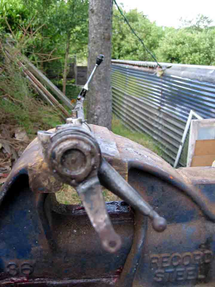
The following pictures were taken during the repair of the gear shift column that broke in Norway.
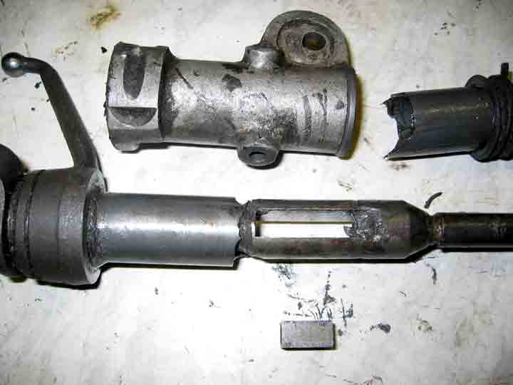
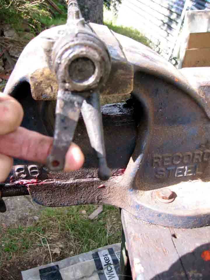
The outer shaft broke across the slot. Note the arm has been turned off to be used on Javelin shaft.
A contributing cause may have been the fatigue of 52 years of abuse on rallies and family motoring. The worn helix caused by corroded balls through ingestion of water perhaps on one of the winter rallies may have added to the stresses. A new inner and outer shaft were needed made up from the bottom of a spare Javelin column, since a Jup one was not available and Javelin ones are different lengths. Note the wire retainer on the ball bearing housing. I dispensed with this on reassembly by using Loctite.
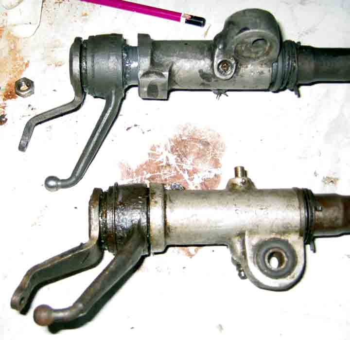
The above shows the floppy broken column at the top before disassembly. Note rubber bush versus aluminium offset one.
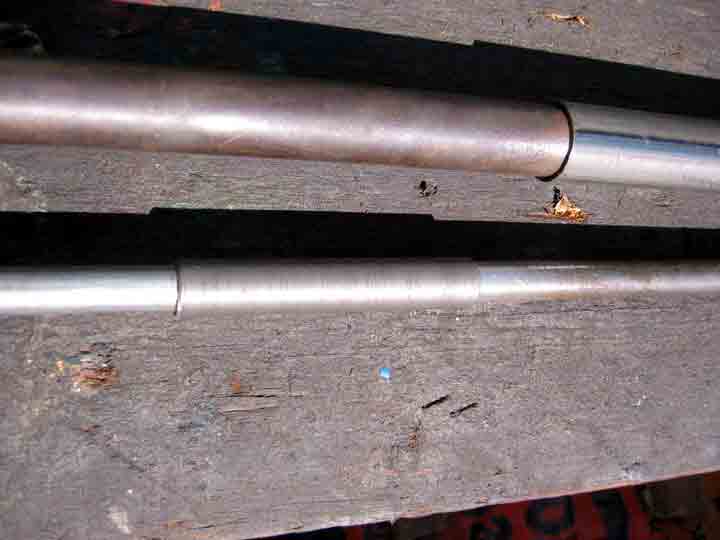
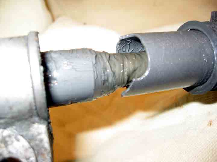
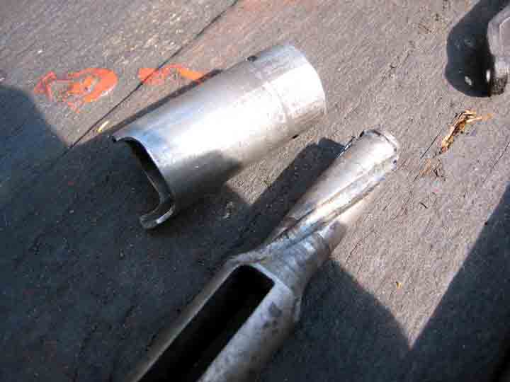
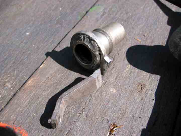
Disassembling a column is by no means easy when you follow the manual and everything is covered in grease (see below); and rebuilding it to the correct orientation even harder. First you need to understand all the components and secondly you need to measure all the angles and lengths before cutting the shafts. Accurate angular alignment is essential. I was going to use part of the broken shaft as a sleeve to join the outer shaft together; but John Blanckley found a longer bit from stock to fit. We had to turn and drill a sleeve for the inner shaft.
Top gear.
Neutral
Third gear.
Reverse
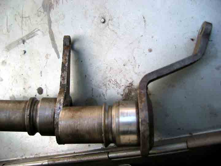
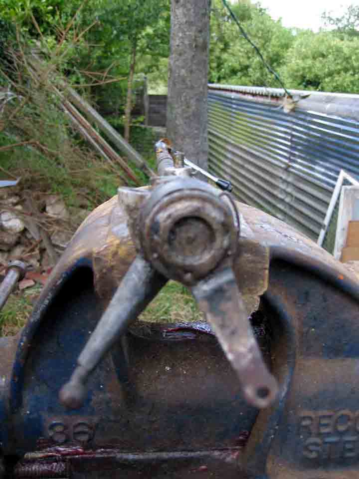
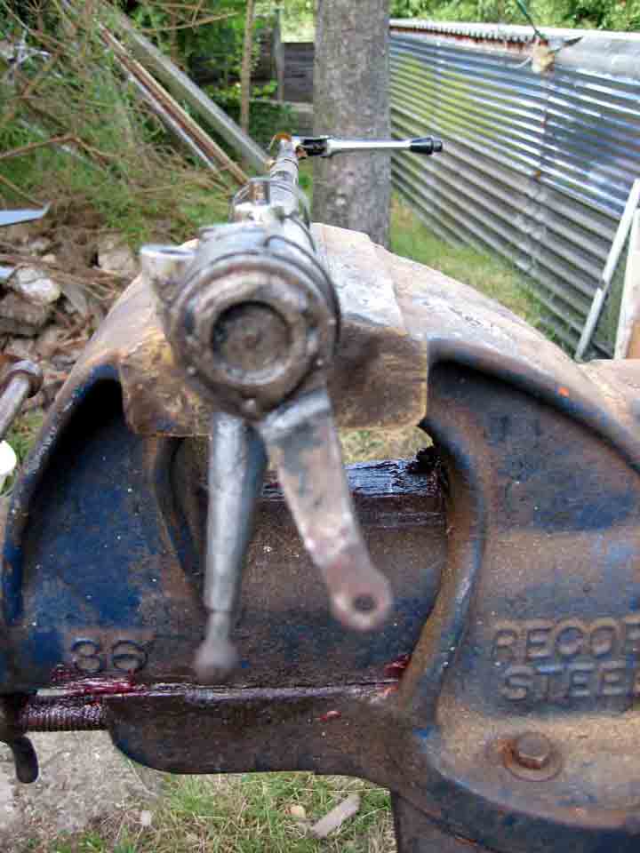
You also need to modify the arms.
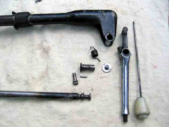
Note the Jup arm was turned off from the broken shaft on a lathe and then welded to the Javelin shaft that had its arm ground off. Quite a major job, since the parts are case hardened. It may have been easier to cut the arm off and weld on as I did with the other arm.
Note the aluminium bush with offset to move gear knob away from dashboard. This replaces the rubber bush. Make sure a washer is large enough on the bolt to the chassis to stop this bush moving.
It is possible to reassemble in the wrong orientation. There may be marks on the parts which should assist but the best thing to do is mark them yourselves.
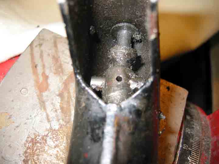
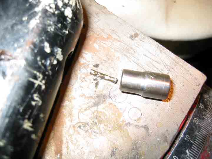
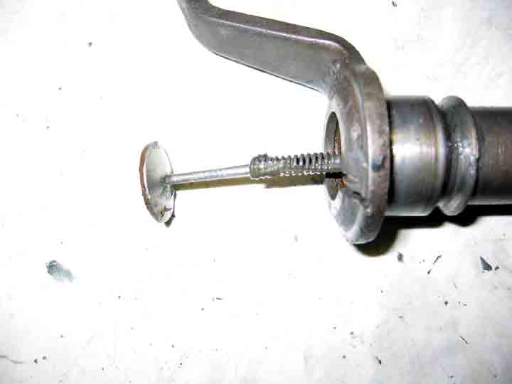
Finding the small clevis pin in the reverse stop pin is not easy. I used a BA socket to act as a support while drifting the pin out with a punch. Note down the orientation of the reverse stop. This helps in reassembly.
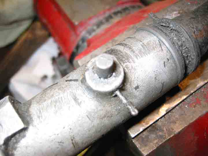
The split pin in the shaft that holds the slider block. Mark position of aluminium housing relative to outer shaft.
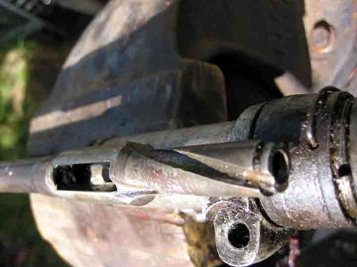
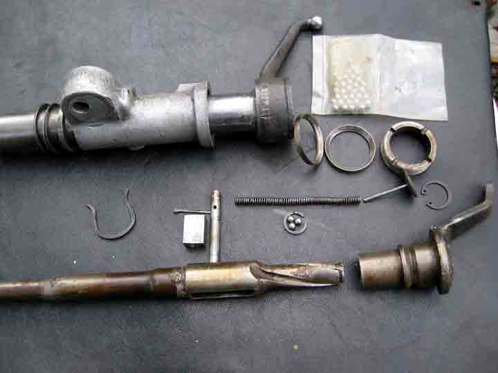
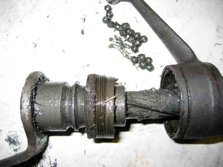
Remove circlip (which is not that easy) and then spring and guide may pop out so cover with cloth! Mine did not and I had to grind a slot to get a lever under it. See? Then remove circlip at top of inner shaft. Three balls are inside helix, do not loose them when removing . Mark position of boss/arm relative to inner shaft. There are three possibilities, only one is correct. Check the grooves are smooth. Try cleaning everything and putting the balls back to test ease of movement. I did not leave it like it on final assembly; but thought that an extra ball in each groove might improve loading and movement.
Removing the wire circlip or perhaps a grub screw means you can turn the castellated retainer. There are two bearing cups and about 18 balls to fall out. On reassembly, I used Loctite rather than screw or clip. I also tightened to give smooth movement without grab and little play.
If you want instructions on removing the column and more detail, try JowettTalk.