Introduction
As
a regular reader of (and irregular contributor to) the Club Journal, I have
often felt that the best use was not being made of the media available. If we
consider, that we must have a combined Jowett experience within the club,
exceeding one thousand years, then the articles printed to date have not reflected
this massive source of knowledge.
I
have decided to have a tilt at the windmill, in the hope that this will aid both
the Editor and the club through supplying a detailed analysis on the Jowett
Javelin/Jupiter gearbox. I do not claim to be an expert on this but act merely
as a catalyst in the reactions which hopefully flow from this epic task. The
aim of the following article is to set the example, starting a little pile on which
you can add your contribution.
I
have tried to set out in a logical manner all the facts that I can think of in
relation to the gearbox. In this area, as in so many others, the manual leaves
a considerable amount unsaid. I have also tried to bear in mind that when the
manual was written, the wearing qualities of the various parts could not have
been predicted. In a way we can use thirty years of hind sight. To this end I
have numbered all the paragraphs evenly, allowing any learned contributor to
add in the "odd" paragraphs where his/her experience can help.
Ultimately we will thus end up with a completely detailed set of instructions
on the gearbox. In addition, should the idea appeal, someone else may care to
write up in similar detail other parts of the car's anatomy.
General Requirements
- The
terms ‘left’ and ‘right’ apply as viewed from the driver’s seat and
looking forward.
- Threaded
studs are screwed into their threads to a torque value that is 20 per cent
of that applied to the nut on final assembly.
- A
clean working environment free of dirt, and clean parts that are free of
rust, oil and dirt are essential, as are a copious supply of clean rags.
All re-used hardware should have been wire-brushed, protective coating
applied (Inox, WD-40 or such) and stored in labelled, re-sealable plastic
bags that are stored in logical groupings, ready for easy location as required.
- The
term ‘wash’ means thorough scrubbing in heavy duty degreasing fluid, rinse
with fresh water and blow dry with clean compressed air. It is assumed
that all parts have been previously cleaned and stored in a sealed
condition. Reference to cleaning and washing here is in addition to this.
- All
references to tightening torque values are given as lb.ft. (pounds. feet)
Greases,
oils, sealants, etc. used:
·
Valvoline
Heavy Duty Degreasing Fluid
·
Nulon
Xtreme L90 Teflon assembly lubricant for all working surfaces (e.g. sliding
selector bars, roller bearings and other slide fit joints)
·
Penrite
SAE 70 – 80 Manual Transmission Oil
·
Penrite
Copper Eze, for studs and bolts that could freeze due to corrosion
·
Loctite
515 Mastergasket sealant – used at gearbox selector cover joint and rear
extension housing joint
·
Loctite
518 Mastergasket sealant – used at all metal to metal joints at oil-wet areas
·
Loctite
Blue RTV (34248) sealant – Rear extension housing seal and speedometer drive
body
·
NOTE:
When applying a ‘smear’ of Loctite sealant, it means just that – a very thin
application of the sealant.. The application should be as even as possible. A
feature of Loctite anaerobic sealants is that they only cure in the absence of
air. They also ‘grow’ during curing.
·
Loctite
Studloc 272 Adhesive – handy to have nearby
·
Loctite
680 Adhesive – used for securing loose gear change lever
·
Loctite
569 Pipe Thread Sealant – used for drain plug
·
Loctite
290 Wick-in Sealant – used for gearbox joints, layshaft spigot, front and rear
shaft bearing outer races
·
Loctite
471 cleaning and accelerator fluid
·
Methylated
spirits – used for final cleaning of surfaces treated with Loctite products
(slows curing rate to permit assembly procedures)
·
Thread
cutting compound, two types – for steel and aluminium
·
Brass
and aluminium drifts of suitable size
·
Aluminium
covers for vice jaws to protect delicate parts
·
Correct
size BSF spanners and sockets
·
Gearbox
components are normally painted as follows:
·
Black
paint is used for rear extension housing, selector change lever, gear change
lever and Layrub coupling companion flange
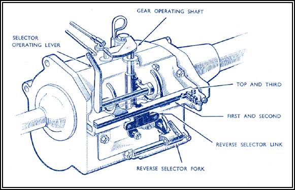
Description Of Gear Selection Operation
1. The
gears are selected in the gearbox by means of two shafts. The gear operating
shaft and the selector change shaft.
2. The
gear operating shaft acts in the vertical plane and can take up three distinct
positions: In the upper position it selects 3rd and 4th (top)
gears. In the intermediate position it selects 1st and 2nd
gears. In the lowest position it selects reverse gear only.
3. Rotation
of the gear operating shaft, allows this shaft to select one or other of the
gears in the upper and middle positions, or one gear in the lower position.
Looked
at from the top, rotation of the shaft clockwise selects 2nd gear and,
4th gear, anticlockwise rotation selects 1st, 3rd
and reverse gears.
4. The
selector change shaft acts in the horizontal plane and by rotation of the
selector change lever, causes the gear operating shaft to take up one of its
three positions.
Looking
from the front of the gearbox, when the selector change lever is at 1 o'clock
the upper selector bar is in operation (3rd and top), at 12 o'clock
the lower selector bar is in operation (1st and 2nd),
and at 11 o'clock NO selector bar is in operation, (in fact the lower bar is locked
to prevent it operating) and reverse gear can be selected.
Inspection Of The Gearbox
5. To
inspect the gear selection of the gearbox when it has been removed from the car
prior to dismantling, or after reassembly, the gearbox should be attached to
the Clutch housing and the clutch shaft cover should be in place. A spare clutch
housing is useful for this exercise. Unless the gearbox is thus attached,
selection of top gear will push forward the front mainshaft ball bearing,
thereby releasing the synchro balls; and springs on the 3rd and 4th
Synchronizer.
6. Check
for excessive play on the clutch (or spigot) shaft. When present this will
indicate either a worn mainshaft front roller bearing, Part No. 50017(the little
caged rollers may have become un-caged), or a worn clutch shaft ball bearing,
Part No. 50014.
7. Check
for excessive play on the vertical gear operating shaft. Where present this
will indicate that the gearbox housing has worn (the bore is oval) and will need
bushing, or that the gear operating lever lug is worn (which will need replacement
or be built up with weld).
8. Depress
the gear operating shaft by hand and select reverse gear. Note whether or not
the gear change lever hits against the stop on top of the casing. In some
instances noted, the gear change lever will strike the base of the stop instead
of the stop itself. This can be rectified by fitting a shim on the outside of
the case below the gear change lever or the lower face of the lever can be
filed off as much as 3 mm to correct the action.
9. On
releasing the operating shaft (after depressing it) check that it returns to
the upper most position naturally. If not the operating shaft spring may be
broken or distorted, or the selector bar notches may not be correctly aligned
(wear in the plunger notches or the plungers themselves allowing the selector
bar to move backwards and forwards) causing the gear operating shaft lever lug
to miss the recess in the bars or catching the edges of the bars.
10. Check
the selector change shaft movement in the horizontal plane. More than 2 mm of
movement fore and aft indicates that take up of wear on the selector lever pad
is necessary by shimming on the outside of the gearbox casing immediately
behind the selector change lever.
11. Check
for cracks in the gearbox casing particularly round the driver's side front lug
(which is definitely prone to cracking) due to insufficient tightening of the
nut and engine vibrations. This can be fixed with the TIG aluminium welding
process. The engine vibration with loose nuts can also cause cracking in the clutch
housing particularly near the openings for the clutch fork.
12. Note
that since the gearbox casing is cast from aluminium (i.e. a soft material,
relatively speaking) which acts also as a bearing medium, all holes in
the gearbox are subject to wear and need careful inspection.
Dismantling
the Gearbox
13. Drain
the oil from the gearbox. It may be helpful to apply some heat so that the plug
can be removed easily.
NOTE:
After removing the drain plug, carefully examine the oil and the inner gearbox
housing to look for metal debris. This will give an indication of how the
gearbox has been treated.
14. The
dismantling of the gearbox is adequately covered in the Jowett Maintenance
Manual Page.50, so little will be said here apart from a few useful hints:
15. Since
this is a description of a major overhaul, definitely drift out the layshaft
thereby allowing the cluster gear to drop into the bottom of the box to enable
removal of the mainshaft.
16. Whilst
it may be possible to "drift out the clutch shaft ball bearing from inside
the gearbox", the use of a especially constructed bearing puller that locates
in the circlip groove is recommended.
NOTE:
When removing the mainshaft bearing, it will be necessary to remove some of the
studs to allow room for the puller to connect in the circlip groove in the
bearing outer race. (See Steps 22 – 24 for stud removal/replacement information).
17. The
removal of the bearing oil thrower from the clutch shaft prior to separating
the clutch and main shafts (first and third motion shafts) gives a little more
room for access.
18. When
separating the clutch shaft from the mainshaft, it will be found easier if the
clutch shaft spigot bearing is pushed as far forward as possible into the
clutch shaft, rather than leaving it on the mainshaft spigot. In addition, the
mainshaft can be withdrawn further to the rear if 2nd gear is
selected carefully, prior to withdrawing the mainshaft through the side of the gearbox
housing.
19. When
removing the gears from the mainshaft, the use of a small narrow bladed
screwdriver is recommended for depressing the plungers of the mainshaft lock
washers.
20. To
remove the reverse gear shaft with ease, use a socket, some washers and a
5/16" BSF setscrew to make up a puller. A tapped hole is provided in the
shaft for this purpose.
21. Dismantle
the entire selector housing cover even though this is NOT mentions! in the manual
as it will need to be refurbished for a complete overhaul anyway. Carefully
determine the operation of each of the levers and shafts in the cover as most
of the trouble with the gearboxes can be traced to them. Once you fully
understand the operation and function you will wonder, like me why there is no
mention of it is made in the Maintenance Manual.
Stud Removal And Replacement
22. To
remove studs from the gearbox, use two nuts of appropriate size for the stud concerned,
and thread these onto the exposed portion of the stud. Lock the lower nut against
the upper nut by tightening the nuts against each other.
23. To
remove the stud, after locking the nuts together, turn the lower nut
anti-clockwise, the stud will unscrew.
24. To
install a stud, after locking the nuts together, turn the upper nut clockwise.
When the stud is fully borne against its shank, release the nuts; by holding
the upper nut still and turning the lower nut clockwise until free, then spin
off each nut individually.
NOTE:
Before installing a stud make sure that the surface around the threaded hole is
flat. Distortion here can cause oil leakage at a poorly seated joint. Apply a
smear of Penrite Copper Eze to the thread when the stud is being installed into
a blind hole. Apply a smear of Loctite 518 Mastergasket if the stud’s hole
breaks through into an oil-wet area.
IMPORTANT:
Studs should be tightened to 20 per cent of the securing nut’s final torque
value.
Inspection Of The
Dismantled Gearbox
25. Gearbox
housing – bearing in mind what has been previously stated about aluminium
housings, thoroughly clean and air dry the housing, inside and out, with good
quality degreasing fluid and rinse thoroughly with clean water.
26. Check
again for cracks around the lugs and around the rear ball bearing. The rear
stud holes are close to the edge of the casting and are prone to cracks also.
Also, check the bore for the mainshaft ball bearing as incorrect (skewed) fitting
can crack the casting.
27. Check
the ball bearing surfaces for signs of the bearing having turned in the case. Score
marks and/or a bluish tinge indicate turning and heating effects. If the
surface is scored or otherwise worn, the gearbox housing will have to be replaced.
If wear is minimal, apply three drops of Loctite 292 Threadloc (wick-in),
equally spaced, between the housing and the bearing outer race. This should be
done after the gearbox has been assembled, and with the components clean and
dry.
28. Check
the underside of the gear operating shaft upper hole for wear. If wear is
apparent, you will need some shims to take up the vertical slack in the shaft
on assembly. Failure to take up this slack will cause the gear operating lever
lug to miss the recesses in the selector bars or to "half" connect in
the recess.
29. Check
the gearbox studs for loose studs or stripped threads. New studs can be
manufactured from 1/4" BSF bolts cutting the bolt on the unthreaded portion
below the head and then using a button die for cutting a 1/4" Whitworth or
BSF thread, depending on the gearbox housing thread, on the unthreaded portion
of the bolt. Enlarged threaded holes should be fitted with Helicoils (Recoils)
whereupon you can use studs with a BSF thread at each end. This is one of the few
instances where JCL mixed threads.
30. Remove
all the studs from the gearbox side and check the surfaces for flatness. Clean
up where necessary with a fine cut file and polish with an emery stone where
the selector bars slide to remove burrs.
31. Check
the 7/16” diameter stud at the front of the box lower RH side for protrusion
into the inside of the housing. It can cause the layshaft front thrust washer
to be pushed out of alignment. Remedy, grind, file or cut the stud to shorten
if necessary.
32. Check
the 5/16" diameter stud at the rear of the housing, lower left hand side,
for protrusion into the housing. It can cause the reverse gear to be pushed forwards,
and clash with first gear.
33. Check
the gear operating shaft bores top and bottom for Ovality. If oval bore them
out to 5/8" and insert bronze bush, DUFOR Part No. 1450, which is long
enough to be cut in two to do both top and bottom bores.
34. Smooth
all rough aluminium bearing surfaces on the selector housing cover by using a
small flat whetting stone to remove scoring where the selector bars have been
in contact with the cover plate.
Gears
35. Thoroughly
clean all the gears with kerosene prior to inspection as the oily surfaces of
the gears hide a multitude of sins. Inspect each gear for wear holding it in a
strong light checking for heat affected areas and pitting. If possible replace
all pitted gears and polish off all sharp edges with a fine emery stone.
36. Check
the synchronizer cones on 2nd, 3rd and top gears for wear
and lap in the gears on the mainshaft with fine grinding paste.
NOTE:
With the synchronizer cone and cup pushed firmly together, the cup should hold
the cone when held up with the cup uppermost. If the cone drops out of its own
accord, the pair of parts are worn.
37. On
completion of lapping, thoroughly clean off all traces of the grinding paste by
using hot soapy water (which will expand the pores of the metal) with a stiff
brush.
.Selector Bars
38. Check
the selector bars for twist and bowing. Straighten with a hammer on a flat
steel plate or anvil.
39. On
completion of straightening, use a smooth file to clean up any nicks or slight
alignment problem. Remove sharp edges with an emery stone to prevent cutting
into the aluminium casing.
40. Check
the selector bars for bowing by holding the bars back to back against a strong
light and looking for gaps.
41. Inspect
the bars for cracks especially round the corners of the recess in the bars
where they connect with the gear operating lever lug.
42. Check
the action of the gear operating lever lug in the recesses of the bars for
reference prior to building up the lug or filling in the recesses of the bars.
File away any high spots on the bars.
43. Inspect
the selector bar notches for "tracks" created by excessive pressure
on the selector plungers. If scored or grooved, the bars will need to be built
up with Stellite welding to maintain their hardness.
44. Check
that the bronze selectors are not loose on the bars. If looseness is found, new
rivets will have to be installed.
Gear Operating Shaft
45. Check
for wear at the top of the shaft and on the bottom. At the top the shaft is
likely to be worn on one side only. If worn, the shaft should be replaced. The
bottom of the shaft is likely to be worn in a tapered manner.
46. If
the shaft is in a chronic state as described above, the housing will be so much
the worse for wear and will need bushing. To do this properly you need to
remove the welch plug at the bottom of the casing. This will then allow the use
of a long boring bar or reamer to align both top and bottom bores. This operation
does require the use of a good quality reamer to fine finish the two bores.
47. Inspect
the gear operating shaft spring for "kinking". This can be straightened
out to some degree through winding the spring onto a round rod and then
squeezing the spring with a pair of pliers. Better still if possible replace the
spring.
48. Examine
the gear change lever for wear. It should fit neatly in the machined flats on
top of the shaft. If loose, build up the shaped hole and file back to shape.
NOTE:
A small amount of rotational movement can be coped with by using Loctite 680
Adhesive during assembly.
49. Examine
the gear operating lever lug for wear and check it in the selector bar recesses
for excessive play. If necessary build up the faces of the lug with weld to match
the recesses better
50. Examine
the lower face of the gear operating lever for wear. This is very important
since excessive wear makes the selection of reverse gear an IMPOSSIBILITY. i.e.
the lug may connect in the recess of the reverse selector link but the locking
mechanism cannot come into play on the 1st and 2nd selector
fork. If the face is badly worn it can be built up with weld and trued back
with a file.
Selector Detent Plungers
51. Check
the detent plungers for excess wear or flatness. Many develop a diamond pattern
on the hemispherical surface which prevents rotation of the plunger.
52. If
necessary have the plungers built up with Stellite weld and ground back to
round (or install new ones).
Reverse Selector
53. Use
an emery stone to true up the rear face of the reverse selector link. The
sliding block rubbing against the aluminium gear selector cover. Smooth action
here aids reverse gear selection.
54. Build
up the face of the reverse selector lock, where it makes contact with the
bottom face of the operating lever, with weld. This will probably have worn in
a crescent shape as a result of rubbing action caused by the lower face of the
operating lever.
NOTE:
If this lever is not built up it makes the locking of the 1st and 2nd
selector fork impossible when selecting reverse gear. As a consequence, you may
collect reverse and second gear at the same time, completely locking-up the gearbox.
Layshaft
55. Examine
the layshaft for wear caused by the layshaft bearings rollers.
NOTE:
If wear has taken place, a new shaft should be installed.
56. The
club has a better version of the original caged-in-brass bearings in stock.
57. Check
that the layshaft is straight. This is best done by pushing it back in the
casing from the rear while all the internals are still out and then seeing if
it lines up cleanly with the front hole. If bent it will not line up with the
hole.
NOTE:
Carry out this check now!
Checking The Gear Cluster End
Float
58. Place
the gearbox housing with the front of the housing mounted on protected vice
jaws and the threads of the front stud protected, so that the open side of the box
faces you. Then tighten the vice against the stud.
59. Now
do a trial assembly of the layshaft group by fitting the layshaft front washer,
Part No. 50071, then the cluster gear, Part No. 50051, fitted with new roller bearings
Part No. 50017, the layshaft rear pad, Part No. 50052, and finally the layshaft
rear washer, Part No. 50051 With this pack stacked inside the housing, insert
the layshaft from the rear.
60. This
step can be made easier by employing a dummy layshaft inside the cluster gear
and bearings assembly. The dummy shaft can be pushed through with the layshaft.
NOTE:
Make sure there is room at the vice jaws for the dummy shaft to pass through
the housing, while supported with one hand against the layshaft.
61. Add
the necessary shims in front of the layshaft front washer until clearance is
less than 0.012” Suitable shims are Gee-Jay Replacement Pack No. 276-2, which
contain twelve 0.005” shims which need to be trimmed to clear the locating
spigot on the front face of the front layshaft washer. Using these shims it is
possible to end up with approximately 0.005” end float, which is the preferred
end float specification.
62. A
dummy layshaft can be cut from a worn layshaft, to a length equal to the cluster
gear and the washers for later assembly ease.
Reassemble The
Selector Cover
63. Having
polished the reverse selector link and built up the reverse selector lock,
reassemble the reverse selector mechanism.
NOTE:
The slotted nuts on the outside of the cover are of two different thicknesses
and that the amount of thread showing on the post and reverse link pin also
varies. Fit the thin nut on the stud showing the least thread. Make sure that
the thin plain washers are placed under their respective nuts.
64. While
these parts are being assembled, apply smears of Nulon L90 Xtreme assembly lubricant
so that the mechanism is properly lubricated.
65. Apply
a smear of Loctite 518 Mastergasket under the plain washers to seal the reverse
selector posts. Wipe away any excess sealant.
66. Tighten
the nuts to hold the posts tight in the selector cover. Nip up, then tighten
further to align the split pin hole with a pair of slots.
67. Check
that the spring on the reverse selector lock is working freely and is not
pinched between the link and the raised portion of the selector cover. Check
the action of the reverse selector shaft, it should be possible to push the
fork along with a firm action by hand. If too tight slacken the screw forcing
the spring and ball in the reverse selector shaft groove until the action is
firm but positive. Check that the action of the reverse selector shaft allows
the spring on the reverse selector lock to perform its function, i.e. return
the reverse selector lock to its free state. Some filing may be necessary on
the reverse selector lock to achieve a smooth action.
Trial Assembly
68. Partially
reassemble the gearbox as follows to check various clearances.
69. Install
the gear operating shaft, operating shaft distance collar, gear operating lever
and spring and fix with the mills pin.
Don't
bother about the woodruff key at this stage. In installing the spring it is
easier to install the spring and the gear operating lever and then sliding the
shaft through the spring and lever.
70. Insert
the straightened and aligned selector bars.
71. Install
the reassembled selector housing cover without the plunger housing and plungers
at this stage. Apply smears of Nulon L90 Xtreme assembly lubricant to the
sliding components. Two stud nuts at each end of the selector cover, adjacent
to the selector bars, can be tightened.
72. This
partial assembly will allow a check the operation of the gear change mechanism
without the gears being present to block your view of the proceedings through
the bearing bores.. The action can be extremely revealing.
73. Note
the following points for adjustment purposes:
(i)
Note the gear operating lever lug location in relation to the upper selector
bar (3rd and top) recess. If it sits too high, shims placed under the distance
collar will fix it.
(ii)
Note the selector change lever assembly fore and aft movement. If too loose,
the pad will not be in contact with the operating shaft. Fit shims behind the
lever on the outside of the housing.
(iii)
Note the action produced by the bottom face of the gear operating lever. This
face is designed to depress onto the reverse selector lock when the gear
operating shaft is in its lowest position, and by see-saw action cause the
other end of the lock to engage onto the 1st and 2nd selector
fork preventing double selection of the gears. If the lock has not been
previously built up, you can now gauge the amount of build up or file down required.
(iv)
Note also that the lower face of the gear operating lever causes locking of
the 1st and 2nd selector fork. If the surface of the reverse selector link is
not smooth, or the edge of the reverse selector lock catches in the recess of
the reverse selector link, or the reverse link lock spring is weak, you may be
stuck in reverse gear forever. Touch up the rough edges with an emery stone or
file the edge of the reverse lock selector as necessary and replace the weak
spring.
(v)
See that the gear change lever on the top side of the casing does not foul on
the gear lever stop when the gear operating shaft is trying to select reverse
gear. If necessary file a part of the bottom face off the lever to overcome
this clearance problem. It is my belief that this is the cause in many cases,
of the gearbox jumping out of reverse gear (i.e. the selector was never fully
home and the ball in the reverse selector fork had not yet reached the groove
in the shaft.
(vi)
Note whether the action of filing the side cover flat has caused the opening
for the selector bars to be too small. If so file down the back of the selector
bars. Bear in mind that you have neither gasket nor sealant between the selector
cover and the housing at this stage so don't be too keen to file down the backs
of the selectors.
(vii)
Check that the recesses in the selector bars produce a full and positive action
with the gear operating lever lug. If necessary fill in the recesses of the
bars with weld and/or build up the face of the lug.
(viii)
When all the above points have been checked and adjusted, reassemble the housing
one more time, but this time include the plunger housing and plungers.
(ix)
Adjust the plunger setting by selecting a position halfway between neutral and 1st
gear. Screw up the plunger adjusting screw till just tight and then release the
screw half a turn and lock with the locknut.
(x)
If everything has gone to plan you will now have spent about 20 hours on the
gearbox and you are more than halfway home. You should hear some nice
"clicks" when selecting any of the gear positions and the action should
be smooth. (I used to think that, the "clicks" were caused by the synchro
balls connecting with the internal grooves of the sliding gears but have since
discovered that this is not so).
It
is now time to start thinking about assembling the gears for the proper
installation into the gearbox.
Reassembling The Gears On To
The Mainshaft (Third Motion Shaft)
74. There
is a missing tooth from the spline of the 1st sliding gear, which
must line up with the drilling in the mainshaft to allow the 1st gear
interlock to work. The use of a piston ring compressor for fixing the greased
springs and synchronizer balls is advised when fitting the 1st and 2nd
gear sliding dog onto its correct sliding gear.
75. The
spring-locating pin and spring can be easier fitted after fitting the
thick mainshaft lock washer as the 1st sliding gear can be moved
back sufficiently to allow the washer to move back with it. Having fitted the
spring and pin, depressing the pin and moving the whole sliding gear forward allows
the thrust washer to fit into the groove in the mainshaft. Lock the washer by
rotating it allowing the pin to enter the washer spline recess and lock in
position.
76. Reference
is made in the Maintenance Manual, to the difference between 2nd
and 3rd gear bronze bushes, it does not state which way the bushes
should face. The answer is that the counter bores on both bushes should face away
from the central mainshaft thrust washer. The orientation of these bushes is
shown in the Spare Parts Catalogue. This is a trap for those who do not know,
as the counter bore in the bush is designed to clear the pin. Since the central
thrust washer is the thin one, it could be considered that the pin would stick
out more on it than on the thick thrust washers. This is not the case.
Note also that the central annular oil way rather than the spiral ones line up
with the drilled hole in the gear for oiling purposes.
77. Fit
the second gear bush and the gear itself.
78. Now
fit the central locating-spring and pin and then fit the thin thrust washer.
Lock the washer by rotating it, as in Step 75..
NOTE:
This thrust washer is prone to cracking. The later washers had a larger
diameter than the thick washers to compensate for the amount of metal needed to
stop the cracks even though it remained the same thickness. These washers were
also known to split
There
is another solution to the problem, it is not too difficult to modify the
related components to accept another thick thrust washer. This requires some skilful
machining, but is entirely successful. Plastic thrust washers can also be considered.
79. Fit
the 3rd gear bronze bush with the recess facing forward (i.e.
towards 4th gear) and then fit third gear itself.
80. Fit
the front locating-spring and pin and then depress the spring and pin through
the hole located in the third gear synchronizer cone, then slide on the front mainshaft
locking washer and lock it by rotating it, as in Step 75.
81. Fit
the 3rd and 4th sliding gear, with the etched numbers on
both it and the sleeve facing in the same direction.
82. This
completes the assembly of the mainshaft.
Reassemble The
Clutch Shaft
83. Insert
the hardened steel spacing ring in the clutch shaft, Insert the main shaft (third
motion shaft) spigot bearing into the clutch shaft, apply a liberal smear of
Nulon L90 Xtreme assembly lubricant.
84. Check
the fit of the clutch shaft on the mainshaft spigot and, if necessary, reduce
the free play by fitting a further spacing ring on the mainshaft.
85. Reassemble
the cluster gear assembly.
86. Insert
the hardened steel spacing rings at either end of the gear cluster.
Insert the bearings at each end of the cluster gear applying Nulon L90 Xtreme assembly
lubricant.
87. Insert
the dummy layshaft to hold the shims, washers, bearings and pad in place as a
group.
Final Assembly
88. Insert
the gear cluster including all shims and pads in the housing and allow it to
drop into the bottom of the housing.
89. Insert
the clutch shaft assembly through the side of the housing.
90. Select
2nd gear on the mainshaft (for easier entry) and insert the
mainshaft assembly through the side of the housing.
91. Now
carefully push the mainshaft spigot into the clutch shaft in a straight-line
action, to prevent damage to the spigot bearing.
92. Grip
the mainshaft in a vice, so that the gears on it are clear of the cluster gear.
93. Line
up the cluster gear and washers with the holes in the housing and insert the
layshaft from the rear of the gearbox, pushing out the dummy shaft as the
layshaft passes. through to the front of the housing. This is not an
easy task.
94. Insert
the reverse gear assembly, with the teeth towards the rear and the selector
collar towards the front.
95. Install
the fr6nt oil thrower disc.
96. Fit
the clutch shaft mainshaft ball bearings and install their circlips. The
bearing bores should be lubricated and the bearings driven home with a suitable
hollow drift.
NOTE:
The bronze speedometer drive gear should be installed at this time.
97. Install
new tab washers, lock the gears and tighten the bearing securing nuts dead
tight. Carefully bend over the tabs against flats on the nuts.
98. Ensure
that the selector cover has the reverse gear selector fork in the right
position, the locking lever lug should lie in the reverse selector link recess.
99. Install
a new extension housing bearing sleeve. The sleeve should be pressed in against
the spacer washer.
100. Install
the rear extension housing roller bearing, followed by the rear spacer washer.
101. The
rear seal should be pressed home against the spacer washer. The currently
available modern seal has a slightly smaller outside diameter. This requires
that the seal be installed with a small bead of Loctite Blue RTV sealant
between the seal and the rear spacer washer.
102. Install
the selector cover, using new gaskets and seal with Loctite 515 Mastergasket
sealant.
103. Install
the rear extension housing using a new gasket and Loctite 515 Mastergasket
sealant.
104. Install
the speedometer drive assembly. Use a smear of Loctite Blue RTV sealant between
the body and the extension housing.
105. Special
care must be taken, when attaching the gearbox assembly to the clutch housing,
to ensure that the gearbox breather tract is not blocked with sealant.
A Final Note – Loose
Layshaft Fit
106. The
layshaft protrudes through the front of the gearbox. There is a hole to
accommodate the layshaft in the clutch housing. What is not commonly known is
that this hole is a large clearance hole.
There
have been some instances of oil leakage from this area, due to loose fit of the
layshaft in the gearbox housing and there is a simple way to repair a loose-fit
shaft. .
The
layshaft diameter is 0.75” and the hole in the clutch housing is nominal 7/8”
diameter. Obtain a cup type core plug with 7/8” outside diameter and press it
cup side facing the gearbox, into the clutch housing. The cup will spigot
firmly over the layshaft spigot. An application of Loctite 290 Super Wick-in
will effect a sound oil-tight seal.