Introduction
Unfortunately, due to the design, age and to assembly methods, the
gearbox has 59 potential oil leakage points. This may seem a large number of
areas where oil leaks can be expected. However, in most circumstances, oil leakage
may be from one or two areas. These notes have been prepared so that leak
source detection will be an easier task. A good understanding of the source of
an oil leak makes the task of rectifying it so much easier.
To start the oil leak source identification, a list of known oil
leakage points and their origin follow.
Note: Part numbers are shown in brackets.
Known Sources Of Oil Leakage And Their
Remedies
1. Blockage
at the gearbox breather tract in front face of gearbox casing (AS50001) and
rear face of clutch housing (50836). As the gearbox warms with use, the oil and
air inside expand. If the breather tract is blocked it can cause leakage at
other points, such as the rear seal, side cover gaskets, speedometer drive
bearing and the oil level dipstick to name a few.
The
most common cause of breather tract blockage is the use of excessive sealant during
assembly, or the use of a gasket that does not have a hole to coincide with the
tract drillings in the gearbox front face and in the clutch housing rear face.
Over
many years' use, the breather tract can become blocked due to front end oil
leakage attracting dust and accumulating in the inside rear face of the clutch
housing. This condition can be particularly active if the clutch cover plate
(50861) is not in place.
2. At
the rear speedo housing extension tube oil seal (50039) lip. There can be a
degree of confusion here. The seal lip runs directly on the surface of the
gearbox third motion shaft – not on the machined surface of the output flange
(50120). In most cases, oil leakage here is due to a seal with sealing lip
material that has hardened with age.
3. At
the rear of the speedo housing extension tube oil seal (50039), between the
seal casing and the extension housing tube. This can be due to poor
installation of the seal into the tube. It can also be due to the loose fit of
a modern seal. The original style seal is no longer available and the modern
substitute can be loose in the extension tube.
To
effect a good seal, the seal outside diameter and the extension tube bore
should be thoroughly cleaned and given a final wipe with methylated spirits.
Once dry, a 2 mm triangular bead of Loctite Blue RTV sealant should be applied
to the rear inner edge of the of the extension tube bore. As the seal is pushed
in, the sealant bead is pushed ahead until the seal and sealant lodges against
the main shaft extension bearing locating washer. Once the seal is home, place
the housing aside for the sealant to cure overnight.
4. Rear
extension housing gasket. Great care needs to be taken with this joint.
There
is a strong temptation to delete the gasket altogether and rely only on
silicone based sealant to take up the gaps. Before attempting such a procedure,
accurate measurements should be taken at the bearing locating ring (50015) thickness,
typically 0.083", and at the rear bearing (50014) protrusion from the
gearbox rear face. Accurate measurements should then be taken for the circlip
and bearing recess counter bores in the front face of the speedo housing
extension. If there is interference (the counter bored recesses are not deep
enough for the housing to hold the bearing forward and make even contact with
the rear gearbox face), consideration must be given to installing a gasket of
appropriate thickness. The use of a silicone sealant will mean that as the
joint is tightened, a film of sealant, 0.001" – 0.002" thick, will
'build-up between the two components. The sealant and/or gasket should not
allow end float that the third motion shaft, by the same token, the shaft and
bearing should not be under the influence of pre-load.
5. At
the selector cover gaskets (50057 and 50058), four leak points here, where the
gasket ends butt against the clutch housing, and speedo housing faces.
Short
gasket ends should be avoided, if they can't be, then a suitable sealant should
be used to fill the gaps that could become oil tracks. Ideally, the clamped
gasket ends should protrude by 0.001". If protrusion is greater, the
surplus gasket can be shaved off with a sharp blade while a feeler gauge is
held against the gasket side. The ends of the gaskets should be compressed when
the front and rear housing joints are made.
6. Along
the gasket surfaces due to age, loose selector cover hardware or pressure build
up inside the gearbox due to a blocked breather tract.
To
effect repairs, new gaskets should be installed against flat clean surfaces,
using Loctite 515 Master Gasket sealant.
7. At
the selector cover securing studs, eight leak points, where oil can migrate
through the gasket material and along the stud to exit at the securing nut
threads.
To
effect repairs, Clean the threads with methylated spirits and place a trace
bead of Loctite 518 Master Gasket sealant. Install clean plain washers and
Nyloc nuts.
8. Again,
at the selector cover securing studs, the stud holes break through into the
oil-wet casing.
To
effect a repair, the selector cover should be removed and the eight studs
removed. The threads should be thoroughly cleaned with methylated spirits. A
smear of Loctite 518 should be applied to each stud before threading it fully
home. Wipe away excess sealant.
9. Furthermore,
at the selector cover securing studs, local distortion due to over-tightened
studs pulling parent metal outwards. Such distortion can, in extreme cases,
hold the cover away from the gasket.
To
effect a repair for this cause of oil leakage, remove all of the studs and make
sure that the gasket surface on the gearbox housing is absolutely flat.
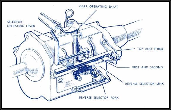
10. At
the selector cover where the selector operating lever and shaft assembly
(AS50101) enters the cover. Oil leakage here usually indicates wear at either
the shaft or the shaft's bore in the cover.
To
effect a repair, it may be necessary to bore the housing and install a bronze
bush.
11. At
loose hardware securing the studs (50077 and 50125) where they exit the
selector cover.
To
effect a repair, remove the cover, remove the slotted nuts and apply a smear of
Loctite 518 beneath the plain washer. Fully tighten the slotted nuts and
install the split pins. Do not back off the nuts to align split pin holes. Try
swapping the two slotted nuts to achieve tight nuts with split pin holes
aligned.
12. At
the selector detent plunger housing (50107), oil leakage due to poor fitting
and/or loose securing hardware.
To
effect a repair, carefully remove the housing, ensure that mating surfaces are
flat and the housing is secured with Loctite 515 sealant. Apply sealant to bolt
threads as well.
13. At
the front and rear of the reverse gear selector shaft (50093).in the base of
the selector cover.
A
repair here may be seen as a difficult repair job – but it is relatively
simple. First, the gearbox should be fully drained. Next, the shaft locating
peg bolt should be removed. Wash both ends of the shaft with methylated spirits
and, while still wet, using a compressed air jet, blow the methylated spirits
into the shaft locating bores. Repeat this several times. Hold down the gear
change operating shaft (50095), against its spring, and, while holding the
shaft down, tap the reverse selector shaft forward until it contacts the cover
securing nut. The selector shaft is actually engaging reverse gear. The third motion
shaft may have to be rotated for the reverse idler gear (AS50075) to mesh with
first gear.
The
exposed shaft at the front and the cover bore at the rear can now be cleaned
with methylated spirits and dried. Apply a smear of Loctite 518 sealant around
the protruding shaft and the rear cover bore. Tap the shaft back into its home
position and, apply a smear of sealant under a clean plain washer, and fully
tighten the peg bolt. Wipe of excess sealant from both ends of the reverse
selector shaft and leave to cure over night.
14. At
the unsupported portion of the speedo housing extension tube (50044). The machined
front face may be distorted, and not effectively clamping the gasket over the
reverse idler shaft (50074) and the layshaft (54409 & 50048).
To
effect a repair, the gasket contact face of the speedo housing must be absolutely
flat. The thin lower portion can be gently bent forwards. Check that the
reverse idler shaft and the lay shaft re slightly forward of the rear gearbox
housing face.
15. At
the bronze welded joint between the cast iron portion and the tubular rear
portion. This joint has been known to crack at high mileage use. If the tube is
a loose fit, the housing should be scrapped.
To
effect a repair, wash thoroughly to remove all traces of oil. Grind away the
existing bronze weld material and have the joint re-welded with bronze weld
rod. After the welding activity, make sure that the front face is flat.
16. There
are three holes drilled into the cast iron portion of the speedo housing. Some
of these holes have been filled with bronze weld material, some have not.
To
effect a repair, thoroughly clean the holes and, in turn with each hole
vertical, wick-in Loctite 290 sealant and allow each to cure in turn.
17. At
the front of the gearbox where the layshaft protrudes and 'spigots' into the
clutch housing. This is a common leak point and no amount of sealant seems to
effect a sound repair.
This
is an interesting one. It seems that the dimensional tolerance between the
layshaft and first motion shaft bores could not be maintained in production. To
get over this inability to maintain tolerance, the hole in the clutch housing
is a big clearance hole.
To
effect a sound repair, thoroughly clean the bore in the clutch housing, obtain
a 0.875" OD cup type core plug and install it in the layshaft bore. The
convex end of the plug should face the clutch and, a method of installation is
to start the plug with a large 'G' clamp. Once the plug is started in the bore,
it can be driven in with a suitable drift until the front face is nearly level
with the front face of the clutch housing inner face. The inside diameter of
the core plug is such that the layshaft will spigot into it. Once the plug is
installed, wick-in Loctite 290 sealant. This is a permanent repair and should
need no further attention.
18. At
the gearbox to clutch housing joint.
Originally
there was a gasket between the two faces. In most cases, the gasket has been deleted
and the joint sealed with propriety sealants. Care needs to be taken when
deleting the gasket, to ensure that the first motion shaft bearing (50014) has
room to be held in the clutch shaft cover (50007) and that there is sufficient
space for the bearing locating ring (50015). The same accurate measurements
should be made here as for the speedo housing at Item 4.
To
effect a repair, a suitable gasket should be cut and installed with sealant. It
is important that a hole be cut for the breather tract.
19. At
the lower gearbox mounting studs (50123). The threaded holes for these studs
break through into the oil wet interior of the gearbox casing.
To
effect a repair, drain the gearbox oil, remove the studs and thoroughly clean
them. Apply a smear of Loctite 518 sealant to the stud thread and install the
studs.
20. At
over-tightened lower gearbox mounting studs. In extreme cases, the metal around
the stud shanks could be distorted and holding the front of the gearbox away
from the clutch housing rear face.
To
effect a repair, drain the oil, remove the studs and locally file the area
around the studs so that the surface is absolutely flat. The studs should be
tightened into the gearbox casing to 20% of the installed securing nut's torque
value.
21. At
the first motion shaft (50020). There is not a conventional oil seal at the
front of the gearbox. There is a close fitting clutch shaft cover (50007), with
a machined reverse scroll on the first motion shaft.
There
are causes that have been identified:
The clutch shaft cover bore is
worn.
The reverse scroll is gummed up
due to sludge and age of oil.
Worn bearings (50014 and 50017)
Absence of oil thrower plate
(50016)
Over-filled gearbox oil level
Loose bearing retaining nut
(50037), allowing the shaft to move backwards and forwards
Clutch
housing that does not match gearbox bearing bores
Methods
of repair are selectable for the above mentioned conditions. There is the
option of installing a new sealed bearing (50014) with seal left in place at
front face of bearing to effect a repair for a worn clutch shaft cover..
22. At
the gear operating shaft (50097) at the top of the gearbox casing.
The
bore for this shaft wears and allows oil to escape.
To
effect a repair, the gearbox casing should be carefully bored and bushed top
and bottom.
23. At
the gear operating shaft welch plug (54246).
To
effect a repair, the existing plug, if still tight, can be wick-in sealed with
Loctite 290 sealant. If plug is loose or distorted, it should be replaced.
24. At
the gear lever stop (50094). The stop is threaded into the gearbox casing and
breaks through into the oil wet area.
To
effect a repair, the stop can be unscrewed by withdrawing the adjustment pin
and unscrewing the stop. Thoroughly clean the threads with methylated spirits
and apply a smear of Loctite 518 sealant prior to reassembly. Make sure that
the stop is adjusted to its original position.
25. At
the oil filler plug gasket (52692).
To
effect a repair, install a new gasket.
26. At
the dipstick (50059). The dipstick hole can become worn.
To
effect a repair, bore and bush the hole so that the dipstick is a snug fit, but
can be easily withdrawn when the gearbox is installed in the car.
27. Finally,
at the gearbox drain plug (50299).
To
effect a repair, drain the oil, clean the threads with methylated spirits and
apply a smear of Loctite 518 sealant to the plug before threading it home. Do
not over-tighten the plug.

SOME STEPS TAKEN TO ENSURE A LEAK-FREE
JUPITER GEARBOX.
Gearbox Breather
 The Jowett
designed gearbox breathing system is rather tortuous and, if a home made gasket
is installed, can easily be blocked-off completely. With old age having crept
up on me, it was decided to install a remote oil filler. This took the form of
a hose barb being inserted in the drilled and tapped original filler cap, a
hose with an 8 mm bore was attached and routed up to the St Andrew's cross
firewall to chassis brace in the centre. A capped fitting was machined from
aluminium hexagon bar, with a brass barb for the oil bottle tube so that
mess-free oil filling could take place. Into the side of the fitting, a hydraulic
breather filter was screwed in. The cap is sealed to the fitting with a fibre
washer.
The Jowett
designed gearbox breathing system is rather tortuous and, if a home made gasket
is installed, can easily be blocked-off completely. With old age having crept
up on me, it was decided to install a remote oil filler. This took the form of
a hose barb being inserted in the drilled and tapped original filler cap, a
hose with an 8 mm bore was attached and routed up to the St Andrew's cross
firewall to chassis brace in the centre. A capped fitting was machined from
aluminium hexagon bar, with a brass barb for the oil bottle tube so that
mess-free oil filling could take place. Into the side of the fitting, a hydraulic
breather filter was screwed in. The cap is sealed to the fitting with a fibre
washer.
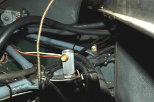
This system, due to the frequency of
filling, works well and the breather filter is washed and dried once a year, to
ensure there is no blockage due to oil vapour attracting dust. The breather
is shown at right, located in tall filler cap.
Gearbox to Clutch Housing Joint
Some time ago, I read about John Blazé's modification to the clutch shaft (first motion shaft), using a flexible
face lip seal of the Forsheda type. See Figure 2, Page 7. The modification
involved machining of the brass clutch shaft cover, Part Number 50007 or
J50007, inside the bell for the seal lip to run on. The depth of the machining
was calculated to provide 2 mm 'crush' at the seal lip. This amount of crush
was determined in discussion with the seal supplier. The machining data was as
follows:
1. The depth of the seal lip contact face in the
bell of the cover is 0.687" (17.45 mm) from the bearing recess. The
machined surface to be smooth for lip seal running.
The bearing recess is the smallest machined
diameter recess, the dimension 0.687" must be taken from this face, not
the circlip recess. The bearing recess face has been found to be consistent.
2. The machined diameter is to be 1.60"
(40.64 mm).
3. An 'O' ring groove, square bottomed, 2.94"
(74.79 mm) is machined into the front face of the clutch shaft housing bell.
This dimension is the centre of the groove section.
The width of the groove is 0.110" (2.90
mm) wide and is 0.090" (2.20 mm) deep to accept an 'O' ring formed from
2.5 mm diameter 'O' ring cord. The arrow shows location of 'O' ring groove.
4. At the flywheel/clutch housing, at the gearbox
joint face, fill breather hole with weld.
5. Looking at gearbox joint face, with straight
edge at bottom, fill the LHS notch that breaks into the clutch shaft cover
recess with weld.
Note: For left hand drive cars, fill the RHS
notch. These notches are for the lever ball pivot, Part Number 50837.
6. Machine surplus weld material from the clutch
shaft cover recess – maintain original diameter and depth of the recess.
7. Machine the entire gearbox face so that when
clutch shaft cover is fully home, its outer surface is absolutely flush with
the gearbox face. This operation will also clean up the weld filled breather
opening.
8. Machine into the joint surface an 'O' ring
groove. The width of the groove is 0.110" (2.90 mm) wide and is
0.090" (2.20 mm) deep to accept an 'O' ring formed from 2.5 mm diameter
'O' ring cord. The groove will be pear shaped to encompass the clutch shaft
cover recess, the RHS throw-out bearing lever pivot and the gearbox layshaft
spigot opening. See accompanying photograph, Figure 3 on Page 7. Total length
of the groove is free, because of the use of 2.50 mm 'O' ring cord.
9. The bore in the clutch housing for the layshaft
spigot is ⅞" diameter, the layshaft spigot has
¾" diameter. A cup type core plug (pressed steel or brass) with an outside
diameter of ⅞" can be used to make an effective
seal. The inside diameter of the plug is a snug fit over the layshaft spigot.
The plug can be installed by using a screw clamp and suitable plates to hold
the clamp square. A smear of Loctite Master Gasket 518 should be applied before
installing the plug.
Assembling the Components
10. The 'O' ring cord should be cut squarely to
length so that, when installed in the grooves, it will not fall out during the
assembly process. Butt join the ends of the cord using Loctite 406 Instant Adhesive.
After adhesive has fully cured, carefully shave off with a sharp blade, excess
adhesive residue. The prepared joint must be seamless, so that when the 'O'
ring is compressed, an oil tight joint is formed.
11. After making sure that the clutch shaft bearing
securing nut is absolutely tight, install the Forsheda seal with a bead of
Loctite Blue RTV (Part Number 34248) to fill the oil scroll groove in the
shaft.
12. Apply a smear of Teflon grease to the seal lip
surface at the clutch shaft cover bell.
13. During the assembly of the gearbox to the clutch
housing, there are two areas that require sealant, the layshaft spigot and the
lever ball pivot. Care needs to be taken here, to ensure that no sealant comes
between the two joining surfaces. Clean the layshaft spigot, its bore in the
clutch housing, the lever ball pivot shank and the bore for that shank. Finish
clean with methylated spirits and apply a smear of Loctite 518 Master Gasket
sealant to the two bores.
14. Assemble the gearbox to the clutch housing and
tighten the four 7/16" BSF nuts progressively until fully tightened. The
finished joint should be sound and there should be no gaps.
15. Wipe away excess sealant from the layshaft
spigot. Clean-up with a rag soaked in methylated spirits and allow to dry.
Apply single coat engine paint to the cup plug installed in the clutch housing
– the sealant is anaerobic and only cures when sealed from air entry, the paint
forms this seal.
16. Apply the same technique as at Item 12, to seal
the lever ball pivot shank to seal that area. The use of an artist's fine paint
brush is recommended.
Adopting the foregoing procedure is, very
likely, similar to an elephant attempting to mate with an ant! In theory there
should not be any pressure within the gearbox to force oil out at the front.
This situation is dependant on a free air flow breather attached to the oil
filler hose. The use of 'O' rings makes the use of liberal amounts of sealant
at the joint surfaces redundant.
Final Comment
Prior to carrying out this modification,
the gearbox jumped out of second gear regularly. The layshaft was found to be a
loose fit in the gearbox housing. Since the layshaft has been spigotted into
the cup type plug installed in the clutch housing bore, the gearbox has not
jumped out of second gear – with about 4,000 miles of use.
To date the gearbox has been oil tight.
Mike Allfrey.
Illustrations
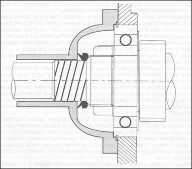
Figure 2. Drawing of Forsheda type seal installation.
NOT TO SCALE
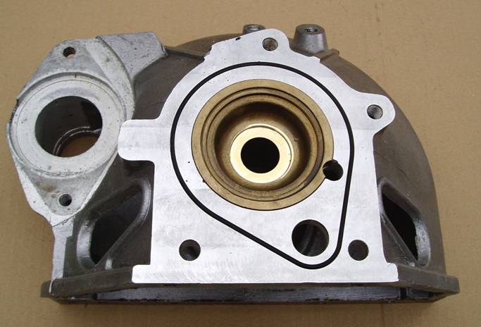
Figure
3. Showing filled breather tract, filled clutch lever pivot hole and 'O' ring
cord.
Also illustrates the machined surface for the Forsheda type seal.
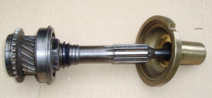
Figure 4. Illustrates the installation of the Forsheda type seal on
the first motion shaft.
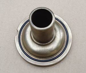
Figure 5. Illustrates the 'O' ring installed in groove.