Introduction
The engine cooling system for the Jowett Javelin and Jupiter motor
cars are very similar and, for convenience here, they are termed 'the Jowett
engine' cooling system. When Jowett Cars Limited wrote their Specification
Notes for the Jowett engine cooling system, the system was described as being
of the 'thermo-siphon' type – assisted by a water pump. Until the advent of the
Javelin saloon and the Jupiter roadster, all Jowett vehicles featured cooling
systems of the thermo-siphon type. It has been frequently stated that the water
pump installation on the Javelin was an afterthought. The same could be said
about the Jupiter's water pump installation, but it has been engineered just
that much better than its sibling.
It is true that the system is assisted by a water pump. The engine
cooling system, as applied to the Javelin and Jupiter, is not of a common type.
The following departures from convention can be noted:
1. The
radiator is mounted to the rear of and above the level of the top of the
crankcase.
2. The
water pump pushes hot water into the radiator's header tank . Most other
manufacturers' systems have the pump pushing cooled water into the cylinder
block.
3. There
are two bottom hoses, one for each cylinder bank.
4. On
the Javelin there is a single, centrally located top radiator feed.
5. On
the Jupiter there is also a single, centrally located top radiator feed that
branches into two to feed each end of the radiator header tank.
6. The
Javelin was one of the first cars to feature air shroud/duct plates for the
cooling fan.
7. The
engine cooling system is serviced by two drain taps, one in each cylinder head.
The radiator, being the highest point in the system, does not require a drain
tap.
Even with all of these differences, the Jowett engine cooling system
will, if properly maintained, function very well.
History
Throughout the engine cooling system's production life, detailed
improvements were introduced. These are best summarised as follows:
1. Air deflectors for the fan were changed to increase the
efficiency of air flow. The change related to a curved edge section adjacent to
the cooling fan's arc.
2. The
water pump front cover was improved by introducing a shroud to better hold
water in the impellor until it was time to be discharged to the thermostat
housing and on to the radiator (D9 PA 5756).
Note:
All Club manufacture front covers feature the cast-in shroud. It is now rare to
find a pump with the early front cover installed.
3. The
fan shaft and rear bushing were increased from 0.500" (12.70 mm) diameter
to 0.625" (15.875 mm) diameter. The fan boss retained the ½" BSF
threaded mounting centre and lock nut.
4. The
fan shaft and fan securing changed to a taper fit with a self locking (Simmons)
nut and plain washer.
5. Following
difficulties in service when removing the fan from the shaft due to taper lock,
a revised taper specification was introduced.
6. The
original fan was of the St Andrew's cross type, with ½" BSF threaded
mounting.
7. A
fan of the St George's cross type with ½" BSF threaded mounting.
8. A
fan as in 7., but with first taper mounting.
9. A
fan as in 7., but with revised taper mounting (E2 PD 20379).
10. A
pressed brass sheet shroud silver soldered or riveted to machined front face of
water pump impellor.
11. Changes
to lubrication methods for fan shaft.
12. Introduction
of improved radiator for Jupiter.
All available Jowett Cars Limited issued Service Bulletins relating
to the engine cooling system are reprinted from Page 7 of this document..
Engine Cooling System Maintenance
Just like any other mechanical component in a motor car, the engine
cooling system can, with great usage and neglect, become worn and tired. This
is particularly so in modern times. It is a fact that most Jowett engines are
now running in a hotter state than was known some fifty years ago. There are
several reasons for this condition, which will be dealt with later.
Hoses
With higher operating temperatures and the banning of some chemicals
that used to be used in the manufacture of rubber hoses, engine cooling system
flexible hose life is reduced somewhat. Ideally, and to provide peace of mind,
the hoses in the cooling system should be changed every two years. Radiator
hoses can suffer due to engine coolant having too strong a corrosion inhibitor
or anti-freeze mixture. If a glycol based anti-freeze is of to great a proportion
of the coolant mix, the hoses will become very soft and will de-laminate.
De-lamination is the term used to describe the separation of the
inner hose liner coming away from the reinforced part of the outer hose. In
severe cases, a water pump can exert sufficient suction to collapse the inner
liner, thus restricting coolant flow. This condition may not be easy to diagnose,
but if the hose suddenly feels softer, this is a fair indication that
de-lamination has occurred.
A coolant hose should be a snug fit on the attaching
barbs/pipes/housings. It should be of sufficient length to accommodate its
securing clamps.
Hose Clamps
There are a number of different style hose clamps available, but
care must be exercised when choosing a clamp. Most clamps are of the worm drive
type. There are many variations on this theme. Some, that are made from very
thin stainless steel, have a coarse pitch worm drive to tighten them. These
hose clamps can, if over tightened, twist to the extent that the rubber outer
wall of the hose can be severely cut. Too often, such hose clamps can be seen
with the rubber projecting through the worm slots.
The original wire type of clamp that was used by Jowett Cars
Limited, if used as it should be, is a very effective clamp. There is also a
very good quality, non-worm drive, clamp made by Würth
of Germany. These clamps can be found at swap meets. The band of the clamp has
a generous radius at each side, thus being gentle on the rubber hose. The smaller diameter Würth clamps are, in
some cases, the only clamp authorised by vehicle manufacturers for fuel
injection hose use.
Hose Installation
There is a technique that should be adopted when installing any new
hose. A new hose should be installed onto clean, corrosion-free, hose barbs.
The hose clamp should be located to the immediate rear of the raised portion of
the hose barb. When installed, the hose itself should be in a relaxed
condition. Only use genuine hoses which can be supplied by the Jowett Car Club
of Australia Inc.
Engine Coolant
To avoid corrosion within the cooling system, it is wise to use a
suitable corrosion inhibitor. For the Javelin and Jupiter engine, which contain
several different metals that make up the cooling system, it is recommended
that a good quality corrosion inhibitor such as Tectaloy Xtra Cool Gold, which
meets AS2108 2004 B. This is a concentrated formula and one litre will make up
fifteen litres of coolant. Add the contents of a one litre bottle to fourteen
litres of soft water, fill the engine cooling system and keep the remainder for
top-up purposes. This ensures that the original mix is not diluted. Tectaloy
Xtra Cool Gold can remain in the cooling system for three (3) years or 37,000
miles, whichever occurs first.
Ford R1-3B Corrosion Inhibitor can also be used in a mix by volume
of 10% R1-3B and 90% clean soft water. This mixture should be drained, flushed
out and replaced with new mixture at two year intervals.
It should be noted that these inhibitors are not an antifreeze type
inhibitor. If using the motor car in sub-zero temperature, taking into account
wind chill factor, conditions, then a propriety type of antifreeze-inhibitor
should be used at recommended strengths.
The coolant mixture needs to be used with extreme care. The balance
between protection and damage is a very delicate chemical specification. Too
little inhibitor will mean corrosion problems at the aluminium components. Too
much inhibitor in the mixture will result in solder bloom problems in the
radiator.
For maximum cooling efficiency, the coolant and cooling system
internal components must be kept absolutely clean.
Perceived High Running Temperatures
Most ‘overheating’ concerns are, in most cases, perceived concern.
This statement needs clarifying.
The Jowett Javelin and Jupiter models are equipped with temperature
gauges that provide reasonably accurate readings between 30°C to 100°C. The temperature gauge provides information that can be interpreted
by the driver. A modern car's temperature gauge that typically displays Cold –
Normal – Hot does not provide specific information, and the 'Normal' segment
can be covered by a large arc of the indicator needle.
The question needs to be asked – What is the 'Normal' operating
temperature for the Jowett engine?
Most are aware that 75°C can be considered to be the normal operating temperature, simply
because it is located at mid-point on the gauge scale. Fair enough. Others know
that the engine is equipped with a 75°C opening thermostat and, therefore, the 'normal' operating
temperature is 75°C. again, a
fair assumption can be made.
That is all very well, but care needs to be taken when interpreting
the 'normal' operating temperature.
Consideration needs to be given to the following points:
1. The cooling system's design criteria probably allows for 'normal'
reading at ambient temperatures in the range of – 10°C to + 25°C.
2. If the ambient temperature is higher than 25°C, then the cooling system will operate at a proportionately higher
'normal' operating temperature. This higher operating temperature can be as
high as 87°C, providing the
engine and its cooling system are in good condition, without any cause for
alarm.
3. Accumulation of dust, oil, insects and other debris on the engine
and radiator will cause higher operating temperatures.
4. Excessive thickness paint on a radiator will form a very good
insulation layer.
5. Scale inside an engine's cooling system also forms an excellent insulator.
6. It is possible that modern petrols do burn (combustion) at higher
temperatures.
7. In metropolitan areas, modern traffic conditions cause the engine to
be running at low-idle for long periods with minimal air flow through the
radiator core. In this situation, should the operating temperature drop back to
'normal' once out on the open road, there is nothing inherently wrong with the
cooling system.
8. A slipping fan belt can cause high operating temperatures. The drive
belt should be wedged in the pulley Vee, if running in the bottom of the Vee,
the belt will slip.
9. Wind direction can have an effect on operating temperatures.
Javelins can be affected more if the wind is from one side than from the other
side.
10. Removing
the thermostat to effect a cure for a perceived overheating concern is not a
recommended practice.
JOWETT CARS LIMITED SERVICE BULLETINS –
COOLING SYSTEM
Bulletin Issue Date: March 1950
Item No. 5. Cooling System
Agents will of course be aware
that with a pressurised cooling system it is essential that the radiator cap is
removed when draining, in order to ensure that the system is completely empty.
Some owners may not,
however, be aware of this and we would therefore strongly recommend that you
emphasise to such owners the importance of carrying out the following drill
when draining:
1. Remove the radiator cap.
2. Open drain taps under cylinder heads and check that water is flowing
freely.
3. As soon as all water is drained from the cooling system, run the
engine for NOT more than 10 seconds.
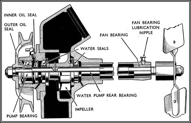
Bulletin Issue Date: April 1950
Item No. 14. Water Pump Housing
From Engine Number E0 PB 8472 an
oil cup has been fitted to the rear of the water pump housing extension tube to
assist the lubrication of the fan bearing.
Refer to Spares Note
Number 28 for parts change information.
Bulletin Issue Date: October 1951
Item No. 61. Overheating – PC Models
There is a possibility that a
number of Bowman manufactured radiators as fitted to Javelin Cars between
approximately Engine Number E1 PC 15910 and E1 PC 17545 have had an excess
thickness of paint applied to the radiator tubes. If under normal working
conditions (not exceptionally hot and sunny days) a thermometer reading in
excess of 81°C is registered,
action should be taken to check the following points:
1. Incorrect ignition timing or faulty action on the automatic
advance and retard mechanism
2. Loss of water.
3. Temperature gauge registering incorrectly.
4. Incorrect Carburettor adjustment.
5. Brakes binding.
6. Thermometer sticking.
7. Fan belt slipping.
8. Blockage in cooling system.
9. Incorrect valve timing.
10. Dash side air vent blockage.
11. Is the mileage and engine performance sufficient to indicate
that a decarbonising service is required?
12. Fan blade angle incorrect.
In the event of the above points
having been checked and found correct and overheating is still experienced,
attention should be focussed on the radiator assembly. If the radiator fitted
to the car is of Bowman manufacture, which may be identified by a plate fitted
to the front of the header tank stamped 'Bowman Birmingham Ltd.', it will be necessary
to take the following action:
1. Remove the radiator block and immerse it in thinners until the
paint on the honeycombing is loosened and peels away.
2. Remove the block from the thinners and direct a medium force of
water through the honeycombing to dislodge any particles of paint which may
still adhere to the tubes, and also neutralize the thinners action.
3. Follow this by blowing through the honeycombing with a strong
jet of air to remove any paint sediment which may be trapped in the
honeycombing.
4. Allow the block to dry and apply a very thin coat of protective
paint to the honeycomb and radiator body.
Note: Where vehicles are operating
in countries where a high ambient temperature is normally experienced, the thermometer
temperature reading will be correspondingly higher than the normal running
temperature of approximately 75 °C and in these cases the above action should only be taken when
normal running temperatures above 87½ °C are registered.
Bulletin Issue Date: October 1951
Item No. 65. Water Pump Modification – PC Models
From Engine Number E1 PC 18140, an
improved type water pump and fan assembly, which embodies the following
modifications has been introduced:
a) Single pressing fan with a taper fitting to the water pump
spindle.
b) A slip ring fitted to the water pump impellor to increase
circulated volume.
c) The internal diameter of the rear fan spindle bearing, Part
Number 50600, has been increased to give additional bearing surface.
d) Threaded studs on the fan spindle bearing housing for the
fitting of the fan support struts with the use of 'Oddie' nuts.
Note: To allow a certain amount of flexibility on the water
pump supporting stays, the 'Oddie' nuts must not be tightened fully down.
The following parts on the new
assembly are not individually interchangeable with corresponding parts on water
pumps prior to Engine Number E1 PC 18140, and stocks of these parts will be
maintained by our Spares Department for servicing requirements:
1. Water Pump Housing (Part Number J54505)
2. Water Pump Spindle (Part Number 54331)
3. Rear Fan Spindle Bearing (Part Number 50600)
4. Fan Assembly (Part Number 53058)
The new type pump, Part Number
J54513, complete with fan assembly is fully interchangeable with the previous
type as a complete unit.
For parts change information
please refer to Spares Note Number 80.
Bulletin Issue Date: March 1952
Item No. 85. Water Pump and Fan – Javelin and
Jupiter
Further to Bulletin Item Number
65, from Javelin Engine Number E2 PD 20379 and Jupiter Engine Number E2 SA 575,
a non stick taper has been introduced to the water pump spindle to facilitate
the removal of the fan. This modification incorporates a sharper taper at the
fan location end of the spindle. The new type fan and spindle are fully interchangeable
as a pair with the types previously fitted, but not as individual items.
For parts information please refer
to Spares Note Number 100.
Bulletin Issue Date: May 1952
Item No. 93. Lubrication of Fan Spindle Bearing –
Javelin
With the introduction of the
radiator mounted oil cooler the fan support tube oil cup, Part Number J54011,
was inaccessible and therefore removed. A 3/16" (4.7625 mm) hole is now
incorporated in the fan support tube for lubrication purposes together with a
1/8" (3.175 mm) spill hole to prevent over lubrication.
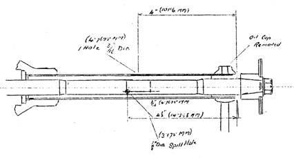
Figure 1. Dimensions for drilling fan support tube.
Bulletin Issue Date: November 1953
Item No. 163. Engine Overheating and Pinking – Javelin
and Jupiter
Cases have occurred where engine
overheating and pinking has been caused by a restriction between the outer wall
of the cylinder head and the cylinder head stud hole casting shown in Figure 1.
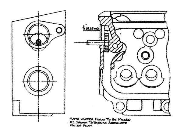
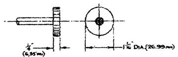
Figure 1. Showing where material can be milled from cylinder head.
In cases of this nature an
adequate water flow between these two points can be ensured by inserting a
Woodruff cutter as shown in Figure 1 through the cylinder head water port,
Figure 1, and milling a ¼" (6.330 mm) passage between the cylinder head outer
wall and the stud hole casting.