TECHNICAL NOTES SERIES
JOWETT JAVELIN – PA, PB, PC, PD & PE
JOWETT JUPITER – SA & SC
PART XV – WATER PUMP, MODIFIED GLAND SEALS
The Jowett Car Club of Australia Incorporated is not responsible for any inaccuracies or changes that may occur within this document. Every effort has been made to ensure total accuracy. It is not a Jowett Car Club publication and, therefore, the Club has no control over its contents. These Technical Notes have been compiled by using the latest information available.
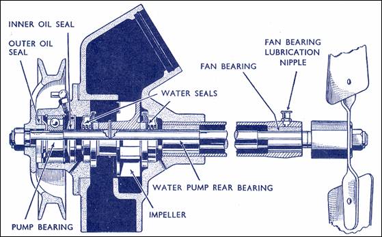
Illustration shows cross section arrangement with early front housing.
Compiled by Mike Allfrey – January, 2006.
Introduction
The authentic style water pump gland seal is no longer commonly available. In the past, the Jowett Car Club of Australia has used automotive style seals sourced from other vehicles. These seals have gone through an evolutionary change, in that the gland bellows is now within the pressure spring, whereas previously it was external. The gland seals supplied by the club, are the modern type.
The Part Number of the currently stocked seal is 50602-PR3440, and it is a dedicated part number. Two are required per water pump assembly.
Because the new design seal has limited crush properties and is slightly different from the original Payen seal, modifications to the water pump front cover, and the water pump housing, must be made. If these modifications are not incorporated, a binding of the pressure seating spring could occur, thus rupturing the internal flexible gland.
Front Cover Machining
Figure 1. shows a cross section drawing of the water pump front cover. The only dimensions of concern are the diameter and depth of the seal recess in the front cover.
![]()
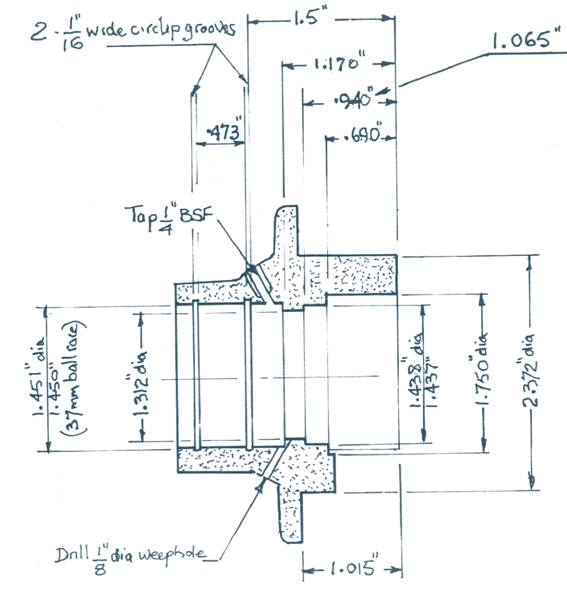
Figure 1. Machining dimensions for front cover.
The modification calls for the dimension 0.940", Figure 1, to be increased to 1.065" (large vertical arrow at right) deep from the rear face of the shroud. The seal's seating flange diameter should be 1.750", The seal recess diameter should be 1.438" – 1.437" diameter. The seal body needs to be a snug fit in this dimension to prevent coolant leakage.
Front Housing Assembly Check
(B)
![]()
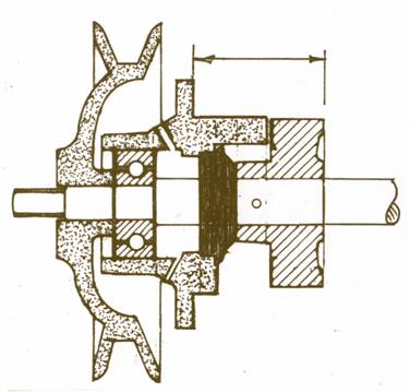
Figure 2. Front cover assembly check.
This check provides confirmation that the impeller (cross-hatched) is set to the correct penetration into the water pump body – dimension (B), Figure 2. This should be:
(1) Gasket face of front cover to rear end of Impeller 1.785" (45.38 mm)
(2) Thickness of front cover gasket 0.031" (0.8 mm)
Therefore actual projection of impeller into pump body 1.755 (44.58 mm) (1 minus 2)
Water Pump Body Modification
With the water pump seal fully pressed into the water pump body, the relaxed front face of the seal must be 1.616" (41.06 mm) to the rear of the front gasket face, (C), Figure 3, refer to Page 3. Setting the seal to this dimension ensures that the assembled 'crush' on the spring loaded portion of the seal is correct.
The seal recess diameter is the same as that for the front cover. The recess for the seal body and the face for the seal lip to seat on will have to be machined to provide the 1.616" (41.06 mm) dimension between the front faces of the seal and water pump body.
Machining Technique – Front Cover
If there is a lathe chuck small enough, the housing can be gripped inside the bearing bore. If the lathe chuck is too large for the method described, a steel mandrel should be machined to fit the bearing bore. The diameter should be such that, if the aluminium housing is warmed, it will shrink securely on to the mandrel as it cools.
Machining Technique – Water Pump Body
The front face and the bore for the front cover spigot must be clean and in good condition. The body assembly should then be mounted on a chuck with the jaws inside the front cover bore. For some lathes, it may be necessary to press out the extension housing, after noting the overall length from front cover gasket face to the rear face of the shaft bush. The orientation of the oil cup should also be carefully noted. The rear boss for the tube can then be lightly machined to provide a concentric grip for the lathe chuck when machining for the new seal.
Assembly of the Components
Both gasket surfaces must be absolutely clean prior to assembly. Apply a light smear of sealant to the body of each seal before they are pressed into the housings. Both seals must be pressed fully home so that the flange lip of the body seats on the machined recess. A genuine gasket at the front cover should be used. A smear of high temperature grease should be applied to the spigot of the front cover where it fits into the water pump body. This will make future dismantling easier. Apply a light smear of gasket sealant to the joint faces and some good quality grease to the fan shaft where it runs in the support bushings.
The front housing, seals, shaft and impeller assembly should be assembled into the water pump housing as an assembly. The front cover grease nipple should be aligned at the top and the cover bolts tightened evenly. Check that the shaft is free to turn with a slight resistance. Assemble the rest of the water pump as described in the Jowett Maintenance Manual.
![]()
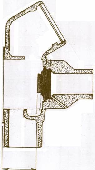
(C)
Figure 3. Dimension taken from front face of relaxed seal.
WARNING!
The water pump gland seals supplied by the Jowett Car Club of Australia Inc. are the result of a great amount of research and, therefore, are of consistent quality. There are a number of seals imported by the automotive trade that are of very similar external dimensions, but do have varying amounts of spring loaded travel. In some cases seals can become over stressed during assembly and leakage or damage to other components will occur.