VALVE CLEARANCE NOISE –
ENGINES WITH SOLID TAPPETS
The engines used in Javelin and Jupiter motor cars have, in some
cases now, been in use for over fifty years. Others, that have not been in
continuous use, have also amassed high mileages. This prodigious amount of use
will, by now, have caused some wear at the camshaft bearing journals, and at
the bearing bores in the crankcase set. Wear in this area is normal – and it
can be confirmed by the fact that an engine's valve clearances are noisy, even
though their adjustment has been carried out as described in the Jowett
Maintenance Manual.
In a push rod actuated over head valve engine, the valve clearance
is still commonly referred to as 'tappet clearance' which is technically
incorrect. In the Javelin engine the clearance is set at the valve stem to
rocker arm tip. This is a different clearance from that between the camshaft
lobe and the cam follower (tappet). The Bradford engine does feature adjustable
tappets.
This phenomenon of excessive valve clearance noise may have been
brought about by several contributing factors:
1. Excessive
wear at the valve actuating rocker tip where it contacts the valve stem. This
condition makes accurate adjustment of valve clearances with feeler gauges very
difficult, if not impossible.
2. Wear
at the valve rocker pivot bush and/or rocker shaft.
3. Abnormal
wear at a pushrod adjusting ball end.
4. Excessive
wear at the valve guides. With the advent of unleaded petrol, this condition is
becoming quite common.
5. Bent
push rods. A bent push rod can 'clatter' within its tunnel in the cylinder
head. A severely bent push rod can flex during operation, causing variances in
valve clearance.
6. Loose
push rod seats in cam followers.
7. Excessive
wear at the camshaft bearing journals.
8. Excessive
wear at the camshaft bearing bores in the crankcase set.
9. Excessive
wear at the timing chain and the chain wheels (sprockets).
All
of the above conditions, excepting the push rod and valve rocker related ones,
can also apply to the Bradford engine. It is of great importance that the
matter of valve clearance noise be prudently investigated. Excessive rocker tip
to valve stem tip clearances can severely affect the life of valve train
components.
To understand
the above mentioned conditions, each valve train component will be discussed in
turn.
The Camshaft
The
camshaft is driven by a Renold Duplex endless chain from the front of the
crankshaft. The camshaft is supported by three bearings located in the top of
the crankcase set. The camshaft's bearing journals rotate direct in the cast
aluminium bearing bores in the crankcase. There are no bearing slippers
(shells).
This type of bearing set up can have an effect on an engine that has
operated for a considerable mileage, in that the camshaft bearing journals and
bearing bore surfaces can wear. This wear can, ultimately, be heard when the
engine is operating at low idle to medium speed as an excessive amount of valve
clearance noise. Severe wear at the camshaft bearings can affect the clearance
between the rocker arm and the valve tip. It should be appreciated that
0.004" wear at the camshaft bearings will translate to 0.006" more
clearance at the valve stem tip. Hence the alarming noise. The fact that there
is valve clearance noise at low idle to medium engine speeds illustrates that
the camshaft is oscillating within the bearing bores.
Wear in this area can explain an oil pressure concern when the
engine has been overhauled. If the engine’s main and big end crankshaft
bearings are in good condition, and the camshaft bearings are severely worn,
oil under pressure will escape from this area.
The camshaft, in good condition should have 0.001” to 0.003” (0.025
– 0.076 mm) running clearance in the bearing bores. With the later style adjustable
peg, it should have minimal end float. The bearing bore diameters should be as
follows:
Numbers 1, 2 and 3 – 1.501" (38.125 mm) diameter
The repair technique for a worn crankcase can be daunting, but if
this is found to be the cause of noise, then something must be done to correct
the condition. One option is to have the crankcase line bored so that the
bearing bores are larger and true. This can be expensive due to the time
required to set-up the crankcase set for the machining activity. Once the bores
have been trued in the crankcase, the camshaft bearing journals can be built up
and ground to provide 0.001” running clearance. At this repair stage
consideration should be given to upgrading the camshaft to provide adjustable
end float that, if excessive, can cause a distinctive engine knock.
A concern here is cost, expect to pay about $200.00 per journal.
This was the method used to reclaim my Jupiter's crankcase and, to date, has
been entirely successful. Jowett Engineering Limited used to bore crankcases
and supply oversize camshafts to suit.
The Cam Followers (Tappets)
The Javelin engine has cam followers that move in precisely machined
bores in the crankcase. The base of the tappet can become severely pitted by
acids in the combustion residue that has a presence inside the crankcase.
Pitting and corrosion are prevalent when the engine is stored for long periods.
This is particularly so if the engine is stopped while in a hot condition. Hot
oil will drain easily from the camshaft and the base of the tappet, leaving the
contact surfaces relatively dry and subject to condensation etc. If long
periods of engine non-use are anticipated, it is a good idea to start the
engine after it has cooled completely and run it for a few seconds so that cold
engine oil is circulated, then the engine should be switched off for the
storage period.
If the bases of the tappets are pitted and/or worn, they can be
refaced and surface treated by a camshaft reconditioner. If this is done, the
lobes on the camshaft should be re-profiled at the same time.
The lobes on the camshaft do not act upon the centre of the tappet,
they are offset a small amount so that as the cam lobe rotates, the tappet also
rotates as does the push rod.
The
Javelin engine can be fitted with several styles of cam followers:
a) The
original full hydraulic type.
b) Solid
type with low profile push rod seat. Requires longer push rod with larger
diameter ball end at non-adjustable end.
c) Solid
type with shroud type push rod seat, to prevent push rod from dropping out
during the situation of valve bounce. Requires longer push rod with larger
diameter ball end at non-adjustable end. This is the preferred solid cam
follower type.
d) Solid
type with extended pushrod seat to suit original length push rods with small
diameter ball end. This was an Australian club modification.
In
the case of items b), c) and d) above, the bronze push rod seat can become
loose in the cam follower bore. This loose condition can cause excessive noise,
a more hollow sound than common tappet rattle. The condition can be repaired by
using Loctite primer and Loctite 680 adhesive. The components should be
thoroughly cleaned, assembled with a smear of the Loctite 680 at the shank that
fits into the cam follower bore. Both items are pushed together and lightly
clamped in a soft jawed vice, to be held until the Loctite has fully cured. Be
sure to clean off any Loctite residue, prior to cam follower installation – or
severe damage can result.
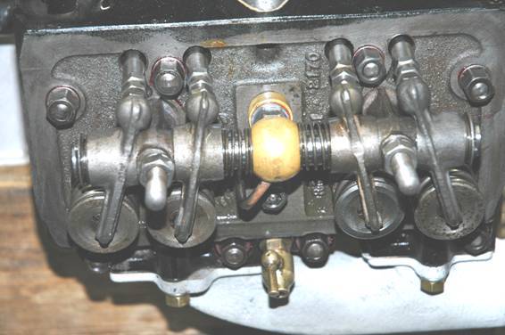
The Rocker Arm Assembly
Inside the engine covers reside the rocker shaft assemblies. The
rocker shaft is a hollow tube that is plugged at each end. There are two
pillars that locate the shaft and rocker arms on the cylinder head. There is an
oil feed via a banjo fitting at the centre cylinder head stud to provide oil at
the rocker arm bushes via small holes in the shaft. There are also drillings in
the rocker arms to feed oil to the ball end of the push rod. This oil feed is
important. Should there be no oil feed, the ball end of the push rod will
become unevenly worn and cause problems during the valve clearance adjustment
process.
There are four types of rocker arms in the complete assembly –
off-set left and off-set right, for both inlet and exhaust valves.
Wear can take place at the cylinder head side of the rocker shaft,
due to the cam lobe moving the cam follower and push rod upwards, against the
force required to move the valve against its spring via the rocker arm. Wear in
this area can cause fluctuations in the rocker arm to valve tip clearance
(sometimes called tappet clearance). Most commonly, difficulty in setting the
correct clearance can be attributed to wear at the rocker bush area.
Wear at the tip where contact is made with the valve stem can be
repaired by having the rocker tips re-profiled. It is also possible to have the
rocker tips Stellite hardened by a welding process. After the welding process
the radius of the rocker tip should be carefully ground to match the centreline
of the valve stem.
Valve Clearance Effects
The valve clearance in any engine, be it side valve, push rod
overhead valve or overhead camshaft type, is of paramount importance to the
longevity of the valve train. The valve clearance should be adjusted at 5,000
mile intervals. There are serious ramifications if this schedule is not
maintained.
As the camshaft lobe rotates the valve is opened from its seated
position. The profile of the cam lobe provides for an acceleration ramp, the
initial valve opening sector, then there is the actual lift of the valve to its
maximum open position. Up to this point, an excessively wide valve clearance
does not have a detrimental effect on the mechanics of the system – apart from
a ‘hammer blow’ at commencement of lift beyond the ramp. Another effect it can
have, with very wide valve clearances, on an engine’s performance is that of
late valve timing, indicated by lethargic engine pick-up from low idle and
difficulty synchronising the carburettors, all related to a low vacuum reading
at low idle.
From the maximum open position of the valve, and towards its closed
position, is when the most damage can be experienced as the result of an
excessively wide valve clearance. The valve closing ramp on the cam lobe has
been carefully designed to control the rate of valve closure. It ensures that
the valve is closed at a controlled rate, thus preventing damage caused by
valve spring dynamism as the valve head contacts the valve seat.
If there is an excessively wide valve clearance, the valve head will
‘hammer’ hard against the valve seat, due to closing in an uncontrolled manner.
The symptoms of this condition in petrol engines are, in severe cases, a
condition called ‘tuliping’. This means that the valve’s seat surface has been
bent away from the valve stem. If this condition is severe, an exhaust valve will
burn away at the edge.
Uncontrolled valves can, in extreme cases, start to break up.
Triangular pieces of the valve’s seat area can break out with ensuing damage to
other components. A valve is machined from a forging, hence the aptness for
breakage in this area, because of the metal’s grain characteristics. This
concern mainly occurs in an engine that has been operating at higher temperatures
than normal.
In the situation where the valve clearance is too small, or a minus
amount, holding the valve part opened at all times, the exhaust valves will
burn away quickly. There would also be, initially, poor engine performance. If
the valve clearance at the inlet valves is too small, or the valve stays partly
open, there could be flash-back through the carburettor. Engine starting would
also be difficult.
An
air/fuel mixture that is too weak can cause the engine to operate in an
overheated condition, causing the exhaust valves to recess into the cylinder
head seats and close the valve to rocker arm tip clearance. Retarded ignition
timing can also generate the same symptom.
A benefit of regular maintenance of the valve clearance adjustment
is that the inside of the engine, where sludge deposits etc accumulate, can be
inspected and remedial action enacted promptly to resolve those concerns that
may be found.
A great amount has been said and written in recent times about the
issue of valve seat recession (VSR), but, there has not been comment about the
importance of tappet clearance with respect to VSR. In all probability this was
due to the fact that writers assume that valve train clearances are properly
maintained. Another point to note is that as the valve seat recedes, the valve
train clearance reduces, in effect a self fixing situation, but the recessive
damage has already been done.
It can be seen that maintenance of the valve clearances is of
fundamental importance. Therefore it should be attended to at regular
intervals, according to vehicle usage.
Investigating Valve Clearance Noise
Maintenance of the valve clearances is compounded by the fact that
Jowett Cars Limited did not have a requirement that, with non-hydraulic
tappets, the valve clearances be adjusted at a specified mileage interval. This
situation can be easily remedied by using industry common service intervals
such as every 5,000 miles or once a year, whichever comes first. With the use
of unleaded petrol, maintenance of the valve clearances is of vital importance.
Investigation of excessive tappet noise should be carefully carried
out. One condition that can cause symptom alarm, is if the noise is noted
inside a garage with a sheet metal roof. Such a roof can amplify the noise
quite considerably. Before any investigation can be executed, the valve
clearances must be properly adjusted. This can be done employing the same
method used by the factory, by setting zero clearance with the engine cold.
This is not an uncommon method for making valve clearance adjustment on an
engine with aluminium crankcase and steel valve train components.
However,
the valve clearances should be adjusted using the procedure shown in the last
Service Bulletin on the subject, issued by Jowett Cars Limited. It is
reproduced in full below:
Bulletin Issue Date: March 1953
Item No. 131. Tappet
Adjustment, Solid Type – Javelin and Jupiter
To clarify the instructions on tappet adjustment the following notes
are issued. It is extremely important in view of the fine adjustment required
that:
1. With the engine COLD the inlet clearance is set to 0.003"
(0.076 mm) and the exhaust to 0.006" (0.152 mm) these dimensions being
measured between the end of the valve stem and the rocker.
2. Ensure that the tappet being adjusted is riding on the base
circle of the cam and NOT on the initial portion of the cam-quietening ramp.
These are two methods of obtaining the above conditions:
a) Adjustment should be made to tappets according to the table
shown below:
Setting Position of Engine Valve to be Adjusted
Number
1 Exhaust valve fully open – Adjust Number 2 Exhaust
Number
1 Inlet valve fully open – Adjust Number 2 Inlet
Number
3 Inlet valve fully open – Adjust Number 4 Inlet
Number
3 Exhaust valve fully open – Number 4 Exhaust
Number
2 Exhaust valve fully open – Adjust Number 1 Exhaust
Number
2 Inlet valve fully open – Adjust Number 1 Inlet
Number
4 Inlet valve fully open – Adjust Number 3 Inlet
Number 4 Exhaust valve fully open – Adjust
Number 3 Exhaust
See chassis number plate on bulkhead to identify cylinder
numbers.
b) The alternative, the best method, is to deal with each valve
individually. Obtain the fully open position of the valve, and then turn the
crankshaft through one complete revolution; this will bring the valve in
question to the fully closed position with the tappet on the base circle
directly opposite the peak of the cam.
End of Service Bulletin.
It
should be noted that the above Service Bulletin has only recently come back
into use. Thanks are due to Peter Jowett and Doug Anderson for downloading it
from the Internet. It is a Service Bulletin that should be regarded as being
current.
The adoption of this modus operandi for valve clearance
adjustment will ensure a quiet running engine – providing the valve train is in
good condition. Personally, I adopt the zero clearance cold method, a remnant
of Royal Enfield motorcycle ownership days. It is also easier to remember!
'Expert' opinion and advice on this procedure should be ignored.
There have been many instances where so-called advice is adopted, with dire
consequences. A favourite is to make the adjustment when the other valve for
that cylinder is fully opened. On a Jowett engine this simply does not work! In
the case of valve clearance adjustment the Service Bulletin has to be
considered as being absolutely correct. There is a situation where 'those in
the know' do not understand the Jowett's valve train. This is the crux of the
matter, because if an incorrect procedure is adopted, incorrect adjustment will
definitely result.
The camshaft in the Jowett Javelin and Jupiter engine is centrally
located and actuates valves located on opposing sides. This means that, even
though the camshaft is short, it still flexes due to valve spring loads. Most
of our so-called experts are probably familiar with inline or vee engines,
where the majority of the valve spring load on the camshaft is from one
direction. On the Javelin and Jupiter engine the loads are from approximately
180° apart. This means that the camshaft is being loaded from side to side. If
the correct valve clearance adjustment procedure is not used and the camshaft
is out of its designated position for such adjustment, the actual valve
clearance could be influenced by abnormal loads, resulting in noisy tappets
when the engine is running.
Recently, the late Ken Lynn, while trying to quieten his Javelin's
engine, carried out some investigations. Ken had been influenced by a
'knowledgeable one' and had adjusted the clearances to those shown in the book,
by having one valve fully open and the other, on the same cylinder, closed.
Further investigation by Ken, after examining the phasing of the cam lobes on a
spare camshaft, revealed that, as the cam was rotated with the cam follower
following the cam lobe's heel, the valve clearances varied considerably. This
caused him great alarm, followed by long telephone conversations to me. I
checked a spare camshaft between two centres and found that between the finish
of the closing ramps and the commencement of the opening ramps, run out was
less than 0.0005". On a used camshaft such a dimension is insignificant.
So, what could be the cause of Ken's alarming findings? Simple
really, flexing of the camshaft due to valve spring loads from the opposite
bank of cylinders. The other cause of Ken's alarming measurements was probably
wear at the camshaft bearing journals and their bores, thus permitting the
camshaft to move sideways.
In the Javelin engine, bearing journal wear can take place at the
sides of the crankcase bearing surfaces. The surfaces of the shaft journals can
also wear. In severe cases, the camshaft can literally float from side to side,
thereby causing variation at the valve clearances. Strangely, it has been found
that more wear can exist at the surfaces of the centre bearing. This condition,
during engine assembly, may not be noticed, but it can be the cause of noisy tappets
once the engine has warmed to normal operating temperature.
What causes this wear?
Probably
the most likely cause is unfiltered engine oil being fed to the bearings. Yes,
the engine does have an oil filter – but, how often has it been serviced? That
is the question. The old style filter using felt as the filtering medium was a
good filter. However, being of the washable type, it probably lasted the life
of the car, in the quest for saving on maintenance costs. No matter how
carefully it was cleaned, some dirt probably ended up where it shouldn't have.
The later paper element type was very good, but was probably subjected to abuse
by neglecting to change it at regular intervals. Both types of filters featured
element blockage protection devices, but that meant that when a blockage
occurred unfiltered oil was by-passed. By-passing oil is not filtered at all,
and the sad thing about this feature is that the driver is not aware when the
element is being by-passed. Another point to beware of, with respect to the
paper element type is that it should be changed at least once a year. Any older
than that and the filtering paper may harden and not filter efficiently.
Experience has shown that aged filter elements can, upon engine start-up, have
pieces of the filtering medium break away – leaving openings for unfiltered oil
to join the feed to vital engine parts.
If
the car is only being used for short runs, corrosive combustion components
build up in the lubricating oil and can cause problems in plain bearings. This
is particularly so if the car is stored for lengthy periods. If this is the
situation, then the engine oil and filter should be changed at shorter time
intervals. The instruction books' schedules are only a guide for
"normal" operating conditions and service intervals should be
adjusted accordingly.
In addition to all of this, oils in days past were not as good as
they are now. Thus considerable wear could have taken place at the camshaft
bearing area. Older oils drained completely away from bearing surfaces when
hot, resulting in dry starts if the car had stood idle for a long period. The
load exerted by eight sets of valve springs on a dry camshaft is considerable
so, during cold engine starts, some wear must take place. In fact, Caterpillar
recommended hand pumping engine oil, via a plug provided, direct into the oil
galleries of its 3208 diesel engine, if started after storage, to protect the
camshaft bearing surfaces.
As a result of the foregoing, it is now more important than ever to
maintain those oil filters and valve clearances!