Introduction
These notes have been prepared using information sourced from the
Jowett Car Club of New Zealand. The modifications described herein are designed
to bring an early style oil pump to, as close as possible, the final
specification of oil pump used in the Jowett Series III engine. These changes
have not been designed to increase engine performance, although they do influence
the durability aspect to some degree.
Jowett Cars Limited found that engine oil delivery to vital
components, could be significantly increased without having to increase the
size of the pumping elements. It was found that by the simple medium of increasing
the size of oil delivery galleries, and the oil suction pipe, oil flow to the
crankshaft bearings was increased. These notes describe how increased flow can
be achieved with an earlier style oil pump assembly/
The Oil Pump’s Development
Initially, in the very early Jowett Javelin motor car, the oil pump
did have a smaller pumping element. The two gears were shorter, and had the
same part number 50668. The very early pumps can best be identified by the
brass oil pump cover and filter assembly, with part number 50674. The brass
pump cover is not recommended for use for these reasons:
- The pressure release valve spool wears at the valve bore in the
housing.
- The brass body can bend due to the weight of the oil pick-up
assembly.
- The shorter pump element gears and corresponding body are not
as efficient as the later type pumps.
- The pump element gears cause wear at the pump cover and become
less efficient.
The next style pump has the longer pump element gears and body to
match them. The gears have two part numbers, 52347 and 52348 The pump cover was
made from cast iron and it also was equipped with a non-adjustable relief valve.
This pump carried over the same size suction and delivery pipes as previously.
The final style pump featured several changes:
- The pump body was lengthened to bring the pumping element
portion closer to the engine oil level for quicker oil pick-up.
- The oil pressure release valve featured a larger diameter
spring.
- The oil pressure release valve was adjustable, using a threaded
spring cap with a lock nut.
- The oil exhausting back to sump was directed to exhaust into
the pump’s suction port. The reason for this change was to minimize
aeration of the exhausted oil
- The diameter of the suction pipe was increased.
- The delivery pipe’s diameter was increased.
- The deeper pump body required a longer drive spindle.
- The deeper pump body required a longer Idler spindle.
It is commonly believed that the Series III oil pump was equipped
with longer pump element gears – this is most certainly not the case.
A number of both later style oil pumps can be found with a pair of
drive-gear pumping element gears.
The Jowett engine oil pumps can best be described here as Types I,
II and III. These identifying types have been used in these notes for
convenience. The subject of these Technical Notes is to describe the modifications
to the Type II pump and its delivery system.
It should be appreciated that the engine, for which the pump is
being modified, should be completely dismantled so that these modifications,
which will only work if the crankcase and rear timing cover are also modified,
it is the total modification that works in harmony.
To Modify The Type II Pump
1. The
pump must be completely dismantled and properly washed before work commences.
2. Using
the bronze welding process, build up the oil pump body in the area forward of
the delivery pipe banjo threaded hole.
NOTE:
This area has to be built up sufficiently to accommodate a suitable sealing
washer.
3. Set
the oil pump body up in a milling machine and, using the ½” threaded hole as a
pilot, spot face the seal washer seat area. Drill the hole out to tapping size
for either the Jowett 5/8” thread, or to take a 16 mm thread. This depends on
the banjo bolt being used. Check the thread pitch on the banjo bolt being used.
NOTE:
Jowett Cars Limited used a non-standard thread pitch for the larger banjo bolt.
The New Zealand club have had a tap specially made for this purpose.
4. Trial
fit the delivery pipe banjo, sealing washers and bolt to check that the bottom
of the bolt can not possibly clash with the pump element gears.
5. If
a clash condition exists, the banjo bolt will require shortening in a lathe.
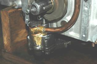
Figure 1: Oil pump body modification,
6. Drill
locking wire holes through the corners of the banjo bolt’s hexagon. Remove any
burrs.
.
Modifying The Cover And Filter Assembly
7. Cut
the suction pipe away from the cover plate.
8. Drill
out the cover plate to snugly accept the larger diameter suction pipe. This
should be of 5/8” nominal bore.
9. Make
sure that all hacksaw and drilling burrs are removed.
10. Cut
the suction pipe out of the strainer assembly.
11. While
the new pipe is still straight, set up in a milling machine and mill a larger
intake slot as per the original pipe. Weld a blanking plate over the end.
12. Bend a new steel suction pipe so that it holds the strainer approximately 8 mm above the
inside face of the engine oil sump.
13. Using
the bronze welding technique, tack weld the components together and, if
necessary, fine tune them into position. Complete the welding process.
NOTE:
After welding it is advisable to ensure that the joints are sound and no air
can be sucked in.
14. If
required, install a new strainer gauze.
15. Out
of 3/8” nominal bore copper tube, form an elbow with a minimal radius, but keeping
the inner bore cross sectional area. This elbow is positioned over the excess
oil exhaust port and should direct the return to sump oil rearwards below
normal oil level.
16. The
elbow should be silver soldered directly over the exhaust port. Care should be
taken to ensure that no solder enters the oil pressure release spool bore. The
spool should be checked for free travel along its entire bore in the cover.
17. Thoroughly
was the cover and filter assembly.
18. Check
that the pump body contact surface is perfectly flat. If any distortion has
taken place, surface grind the surface absolutely flat.
19. Wash
the cover assembly, the release valve spool, spring and its keeper. Lubricate
the parts with clean engine oil. Assemble these components into the cover and
fasten with a hardened split pin.
20. Place
the assembly in a plastic bag for storage.
Modifying The Oil Delivery Pipe
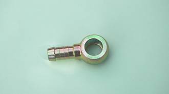
Figure 2: A steel banjo fitting.
21. When
improvements are made to the suction side of the oil pump, they have to be
followed on the delivery side. This can be done quite easily by using a ½” bore
(nominal) copper tube. A larger banjo fitting, as shown in Figure 2, can be obtained
from a supplier of hydraulic fittings.
Modern Banjos come with
hose barbs and are made from steel that has been zinc plated.
22. Cut
the barbs off at the banjo outlet boss.
23. Enlarge
the outlet bore to 11 mm diameter.
24. The
copper tube should fit over the outlet boss.
25. Remove
the original delivery pipe from the oil delivery elbow.
26. Drill
out the inlet and outlet passages to provide an 11 mm diameter oil passage
through the elbow.
27. Make
sure that the copper tube fits over the inlet boss of the elbow.
28. Bolt
the elbow to the front of the crankcase.
29. Install
the modified oil pump body on to the crankcase. Make sure that it is in its
fully home position on both dowels.
30. Bend
the annealed copper tube to follow the shape of the original delivery pipe, and
so that the new pipe sits close to the front face of the crankcase.
The
new pipe should be fitted over the bosses on the banjo and the delivery elbow.
NOTE:
Caution needs to be taken – the very early engines had delivery elbows that had
different bolt orientation. Make sure the pipe is being fabricated on the same
style crankcase as that being used for the modified pump assembly.
31. Make
sure that the banjo fitting at the pump is mounted on its sealing washer and
the bolt is tight.
32. Before
silver soldering the two joints, ensure that there is clearance for the timing
chain. The final lay of the pipe should be the sane as shown on the front cover
of this booklet.
33. Once
the pipe and fittings have been silver soldered, the assembly should be allowed
to cool. The pipe assembly can then be removed and tested for leaks using water
and compressed air.
Check
also that the jet orifice, that directs oil to the timing chain, is still
clear.
34. The
pipe assembly should be thoroughly washed and have any soldering flux residue
removed.
Modifying The Crankcase
The oil path beyond the oil delivery pipe elbow should also be
modified. This requires that the LHS half of the crankcase to be mounted in a
suitable drill press;
35. Drill
the inlet gallery to 11 mm diameter. This is a straightforward 90° to the face drilling exercise. Do not
drill deeper into the crankcase.
36. Set
the crankcase half up on the drilling table so that a drill the size of the
original outlet to the filter gallery passes, freely up and down as the handle
of the drill is actuated. Remove this drill from the chuck and install an 11 mm
diameter drill.
NOTE:
Because the drilling is at an angle to the surface of the crankcase, where the
rear timing cover sits, it is advisable to use a short drill, It is a good idea
to have a larger diameter centre-drill ground to 11 mm diameter to achieve a rigid
drill bit for this operation.
37. Using
the same method, the two galleries that enter the longitudinal galleries, can
be enlarged to 8 mm diameter.
NOTE:
Extreme care needs to be taken here. There is a possibility that these
drillings are very close to the attaching setscrew threaded holes. If this is
the case, the galleries can be counter-bored and aluminium plugs pressed in The
centres for the galleries can be marked out further away from the threaded
holes and then re-drilled with an 8 mm diameter drill.
Modifying The Rear Timing Cover
During
the Jowett engine’s production life, there were three different rear timing
covers. The earlier filter, known as the Vokes oil filter is easiest identified
by the green canister it uses. This, Type I filter assembly filters the oil by
having it pass through the felt element from the inside to the outside.
The
Type II rear timing cover was an updated system that featured a ‘blocked filter
by-pass valve’ and the filtration was manufactured by Tecalemit. This type rear
timing cover can be easily identified by the two ports that supply engine oil
to an oil cooler. The filter medium in this filter is paper and the oil passes
through from the outside through the paper into the centre of the element.
The
Type III rear timing cover is essentially the same as the Type II. The only
difference being that the oil galleries are larger and the oil cooler ports are
also larger. This version, obviously, does not require modification to match
those discussed for the pump and crankcase.
Described
here are the modifications to the Type II rear timing cover to match the other
modifications:
38. The
rear timing cover should be completely dismantled, that includes removal of the
blocked filter by-pass valve.
39. Great
care has to be adopted when opening out the oil galleries in the cover.
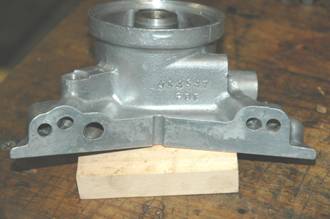
Figure 3: The oil galleries to be enlarged.
40. In
Figure 3. the galleries adjacent to the fixing setscrew holes should be opened
out to 8 mm diameter. To do this, carefully set the housing up on a drill press
table so that a drill the same size as the original oil gallery diameter,
mounted in the drill chuck, passes freely in and out of the gallery bore. This
drill should not bind as it travels down into the bore. Remove this drill and
insert an 8 mm drill to carefully bore the gallery.
NOTE:
Feed the drill slowly. Do not be tempted to increase the depth of the bore.
41. Repeat
this process with the drilling adjacent to the other fixing hole.
42. Set
the housing up on the table so that the large oil gallery can be drilled, using
the same procedure, as described in Step 40, to 11 mm diameter.
43. Using
a beam of light, check that the drilling process has not broken through the
gallery walls.
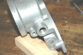
Figure 4: Larger diameter return from filter port.
43. Mount
the cover on the drill table so that the return, from oil cooler, port and
gallery can be drilled.
NOTE:
Drill the actual gallery out to 8 mm diameter using the same procedure as
described in Step 40. The drill for this operation may need to be of the
long-series type.
DO
NOT deepen this gallery.
44. Enlarge
the banjo bolt drilling so that a thread can be tapped for a 16 mm banjo bolt.
45. Inspect
the drilling with a beam of light to check if the drill has broken through the
gallery wall.
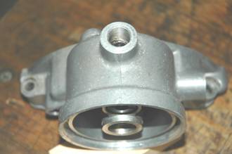
Figure 5: Showing the enlarged outlet port.
46. Mount
the cover on the drill press table so that the out, to oil cooler, port and
gallery can be enlarged.
The
thread should be the same as described in Step 44.
NOTE:
Take care when the drill breaks through into the horizontal gallery. Do not
drill deeper.
That
completes the oil gallery and port enlargement process. If there is an instance
of oil gallery break-through the outer wall should be built up using the aluminium
Tig-welding process. The welded gallery should then be carefully re-drilled to
clean up any weld that may have penetrated.
It is
not really advisable to modify the Type I (Vokes) oil filter housing, because
there is not a great amount of wall thickness to permit enlargement of the
galleries. It is best to restrict modification to the Type II rear timing cover
only. It is understood that these were fitted to engines with the PD prefix in
the serial number.
Oil Gallery Finish
There
is a train of thought that considers the finish of the oil galleries as being
of utmost importance. The gallery walls must be as smooth as possible and
without any burrs that could be dislodged. Hence the call for slow feeding of
the drill during the drilling operation.
Another
consideration that is deemed important is that of the gallery end profile. It
is judged that the gallery end should be finished with a radiused-end cutter in
favour of the normal drill cutting edge angle. This does require extra tooling,
but can be beneficial in terms of oil flow dynamics.
Modifying The Oil Transfer Pipe
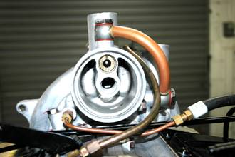
Figure 6: Showing an installed oil transfer pipe.
In
most cases, with respect to the Javelin. the Type II rear timing cover is not
attached to an oil cooler. This installation requires the provision of an oil
transfer pipe as shown in Figure 6. There are several points to consider when
making up such a pipe:
a) If
the engine has been fitted with a Series III front timing cover. If so,
allowance must be provided to let the formed pipe clear the rear distributor
mounting lug on the timing cover.
b) The
breather pipe assembly may require careful bending to allow for the larger
diameter oil transfer pipe to clear it. See Figure 6.
Make
up the pipe as follows:
47. Use
the same diameter copper tube as for the oil pump delivery pipe.
48. Use
the same banjo fittings (Figure 2.) as for the oil pump delivery pipe.
49. Cut
the hose barbs off the banjo fittings and drill out inlet ports to 11 mm
diameter. Clean up any burrs that may be present.
50. Mount
the banjo fittings on the rear timing cover ports with banjo bolts and sealing
washers.
Make
sure that the top fitting exits towards the RHS, but angled towards the rear
slightly.
Make
sure that the side mounted fitting exits towards the top, but is also angled
slightly towards the rear.
51. Form
the copper tube so that it forms a graceful curve rearwards and sits over the
bosses on the banjo fittings.
NOTE:
Make sure that the oil transfer pipe will not foul the engine oil filter
canister. See figure 6.
52. Silver
solder the joints so that they are strong and oil tight. Test with compressed
air, while the pipe is immersed in water.
53. For
appearance, the oil transfer pipe can be polished and treated with a clear
lacquer.
Installing The Modified Components
54. Measure
the oil passage holes in the banjo bolts and enlarge to provide the same, in
total, cross sectional area as the pipe work they are used for. Enlarge these
holes if possible.
55. Wash
and air-dry all components before assembling to the engine. Make sure that the
blocked oil filter by pass valve is in good condition
56. It
is a good idea to use 16 mm Dowty washers at all of the banjo fittings. A Dowty
washer features a lipped seal bonded to its inner diameter. These washers, used
on smooth surfaces, form an oil tight seal without requiring excessive torque
values at the banjo bolts. This is a particularly useful feature if the oil
passages in the banjo bolts have been enlarged.
Testing The Oil Pump
The
oil pump can be tested and adjusted as follows:
57 Mount
the oil pump assembly on to a suitable test stand.
58. Connect
the delivery pipe to an oil pressure gauge.
59. Fill
a tub with SAE 30 engine oil, so that it fully covers the intake filter
housing.
60. Use
a cut off end of a distributor drive shaft set in the chuck of a reversible
electric drill. The drill should, ideally, be of the variable speed type.
61. Set
the drill speed to high ratio, and to run in anti-clockwise direction.
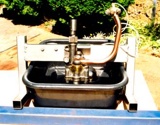
Figure 7: Oil pump test rig.
62. Hold
the drill firmly, but with some flexibility, so that once the speed is
increased the drill assumes, in the hands, a steady attitude and does not try
to orbit. Gradually bring up the speed until the drill is operating at maximum
speed.
NOTE:
This is were it gets messy. As oil is sucked in and delivered under pressure, there
will be jets of oil at the delivery elbow and from the top of the idler element
spindle. These jets are there to lubricate the timing chain and the oil pump
drive gear.
The
latest version of the test rig has built in deflectors to direct the jets back
into the oil container.
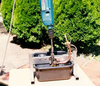
Figure 8: Showing the electric drill drive.
63. The
oil pressure should read 60 – 75 psi. If the pressure is low, it can be
increased by installing shims under the spring. Such shims are not a stocked
item, and therefore will need to be made.
If
the pressure is too high, a small portion of the spring can be ground off
carefully.
Setting
the pressure is a trial and error procedure.
64. If
the pump cover features an adjustable release valve – screw the adjuster
inwards to increase pressure, and outwards to decrease the pressure. Lock up
the jam nut each time an adjustment is made. Recheck the pressure each time.
65. Hang
up the oil pump and allow it to drain completely
66. It
should be noted that 2,000 rpm at the drill represents 4,000 crankshaft rpm.
Further Illustrations
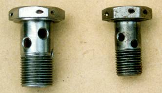
Figure 9: Comparison of larger banjo bolt.
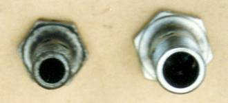
Figure 10: Shows difference in bore size.
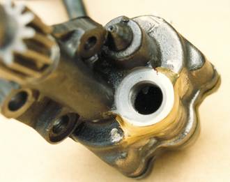
Figure 11: Illustrates built up pump body.
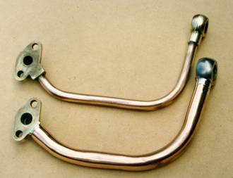
Figure 12: Illustrates difference in delivery pipes.
Note
the smooth bend of the copper tube and how it fits over the banjo fitting and
the delivery elbow.
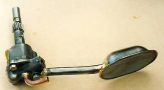
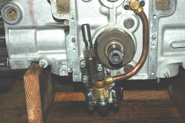
Figure 13: The modified oil pump assembly
Note the larger diameter pick up pipe and the oil return elbow. The
added material to the pump body can just be seen at left.
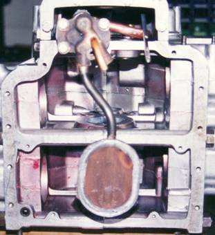
Figure 14: Trial assembly to a crankcase set.
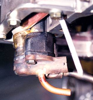
Figure 15: Return elbow position.
Note that the elbow exits well below the bottom of the dipstick.