Introduction
From as early as 1910 the Jowett Company had manufactured cars and
light commercial vehicles that featured horizontally opposed twin cylinder
engines. They were of 6 – 8 horsepower, with the 8 horsepower version surviving
until the cessation of manufacture in 1953. Its final use was in the Bradford range of light commercial vehicles. In the years prior to the Second World War the
company decided to add a horizontally opposed four-cylinder engine to their
range.
After much experimentation a horizontally opposed side valve engine
was introduced in the Jason saloon at the 1936 London motor show. Later, a twin
carburettor Jupiter model was introduced. This engine remained in production
until the commencement of WW II. After the war the flat four engine type was
further exploited by Jowett Cars Limited when the Javelin saloon was introduced
in late 1947. Both the car and its engine were completely new. This exciting
new car was the result of new manufacturing techniques and procedures that had
not been used previously by the Company. Indeed, some of the new production
techniques were pioneered by Jowett Cars Limited.
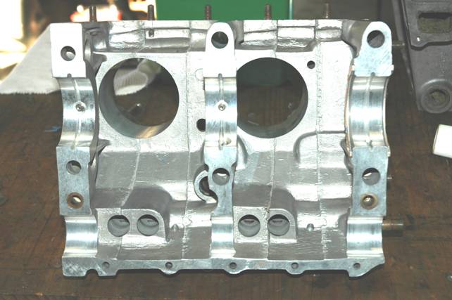
The engine used in the Javelin featured a die-cast aluminium
crankcase that was joined along its centreline and featured wet cast iron
cylinder liners. It was the first mass produced motorcar to feature a die-cast
aluminium crankcase (cylinder block).
The centreline joint was a new production technique for the factory.
All previous engines manufactured by Jowett had one-piece aluminium crankcases
that used separate cylinder barrels attached to each side. Indeed, this type
was first considered for the Javelin it its initial design stage. However, with
the need for higher engine performance that could be ably produced by the proposed
overhead valve configuration, there was a need for a well supported three main
bearing crankshaft. It was soon determined that a split, well reinforced crankcase
would be the most satisfactory route to take. A single piece aluminium crankcase
was tried, but it was found to transmit an excessive amount of engine noise and
the centre main bearing was difficult to hold rigid.
Thus, after considerable development work and testing of different
types and metals, for the crankcase, it was decided to use the die-cast, centre
joint line, aluminium crankcase in production. Improvements made to the
original design will be discussed later.
The crankcase used in the Javelin and
Jupiter motorcars is, if cared for properly, an extremely durable unit. The concerns
that can be attributed to the crankcase's design are mostly generated by the
failure of other components, or by misunderstanding of the Jowett engine's assembly
requirements.
Crankcase Identification
The primary aspect of crankcase identification is to establish
whether the crankcase assembly is a matched set. There is a set number stamped
into the upper face of the front of each half. These numbers, which can differ
from the engine number, are unique to the crankcase set. They are not as prominently
stamped as the engine's Serial Number is stamped into its plinth. It is vitally
important that the set numbers match.
The Engine Number can assist in identifying the type of crankcase
set being examined. Engine Numbers with the letters PA, PB, PC, PD and SA
within them indicate that the crankcase is of the earlier type. Those engine
Numbers containing PE and SC can be considered to be of the later type.
However, some PD Javelins and SA Jupiters were equipped with the later style
sets.
In addition to the above, there were sets of crankcases of the
earlier type that had enlarged oil galleries and machined oil grooves in the
main bearing supports.
The engineering changes and Engine Number break points were as
follows:
E1 PC 16744 Oil groove added to
main bearing bore.
E2
PD 21937 Crankcase oil flow increased.
E2
PD 22190 Redesigned crankcase introduced.
E2
PD 22221 Series III engine introduced.
E2
SA 882 Series III engine introduced.
Set
No. 26574 Synthetic rubber liner seal fitted.
Set
No. 26496 Oil gallery plugs improved.
There are
three basic crankcase castings, which appear, and can be identified as follows:
1. The
very early crankcase similar in detail to the drawings in the various parts
lists. It is a definitely heavier casting and the most noticeable difference is
a flange formed above the sump rim.
2. The
most common die cast crankcase.
3. The
Series III crankcase which has radial webs around the main bearing supports and
is stamped '3' on the shoulder above the petrol pump mounting, and 'PE' above
the engine number.
There are
other differences too, which arise in all forms of crankcase since many
reconditioned engines had crankcases modified to bring them as close to the Series
III type as possible. These modifications included machining an oil way in the
main bearing seatings and opening up the oil drilling from the oil delivery
pipe to the later Tecalemit type rear timing cover. Moreover, some Phase I and
Phase II engines had their crankcases replaced by new crankcase sets of Series
III type, but without any outward marks of '3' or 'PE', but simply the copy of
the previous engine numbers.
The crankcase
halves were always made in pairs, particularly as far as machining of the main
bearing and camshaft bores were concerned. Curiously enough the drilling of the
main bearing supports was not absolutely identical in all crankcases, and in
fact, the centre line of the crankshaft can move from side to side and up and
down with reference to the crankcase. Naturally, this means that the likelihood
of two random crankcase halves matching is remote and they will probably differ
to a degree, which makes it impossible to put them together. The error in
machining the main bearing supports slightly to the left or right of centre is
decidedly worrying when it is encountered, since it is obvious that one bearing
shell protrudes above the face of the crankcase in which it is located and, of
course, the matching half looks to be too small for the housing.
A more obscure difficulty is related to this problem of one-off boring
of crankcases. Whilst it is often assumed that any flywheel/clutch housing will
fit any crankcase, this is not exactly so. The bore in the rear of the housing
which takes the gearbox clutch shaft cover is also machined to match the
crankcase – at least it should be according to the original Jowett Cars Limited
manufacture. That is to say it was centred on the main bearing bores in the
crankcase with which the flywheel/clutch housing should have been used. Thus it
is just possible that the wrong housing would put the clutch friction disc far
enough out of centre and alignment to cause trouble with excessive wear, judder
etc. It is fortunate that this cause of trouble at the clutch has not been
traced, but it is certainly a possibility.
Another difference less commonly observed in crankcases is that of
the oil feed holes to the tappets. On the original hydraulic tappet crankcases
the oil galleries were drilled so that the diameter broke through into the
tappet bores and thus there would be large oil supply holes, which varied quite
an amount in size. Usually they were between ¼" and ⅜" in diameter. When solid
tappets were introduced these large oil feed holes became an obvious source of
oil pressure loss and of course, the solid tappets required only a relatively
small feed of oil for lubrication. Therefore on Series III crankcases and on
some later crankcases of the earlier type, the oil galleries were drilled above
the tappet bores and do not intersect them. The oil feed is about 1/16" diameter
drilled obliquely into the gallery, drilling from the inside of the crankcase
through the mouth of the tappet bore. This means that the oil feed hole is
insufficiently large to operate hydraulic tappets properly and in any case is
not correctly situated. It also means that low oil pressure at low idle with
solid tappets on an otherwise good engine can be related to the oil loss from
hydraulic type oil feed holes in the tappet bore. A further complication worthy
of mention is that some Series III crankcases were certainly made for hydraulic
tappets, and the only way to find out is to remove a tappet and feel for the
drilling with your little finger.
Crankcase Specification
The following specifications apply to the crankcase used in Javelin
and Jupiter motorcars:
Material DTD
133B Aluminium alloy
Cylinder
Head Studs 3/8" dia. EN16 Steel
Bore
for Liners 3.1895" – 3.1880" (81.0133 – 80.9752 mm)
Bore
for Tappets 0.8130" – 0.8135" (20.6502 – 20.6629 mm)
Bore
for Camshaft 1.502" – 1.501" (38.1508 – 38.1254 mm)
Distance between main bearing bore
and camshaft bore 4.413" – 4.418" (112.090 – 112.217 mm)
Bore
for Main Bearing 2.395" (60.833 mm)
Clutch
Housing Dedicated to Crankcase Set
Inspection
Before using a crankcase for engine overhauling purposes, it should
be carefully inspected. The crankcase set should be thoroughly cleaned prior to
examination. It is wise to check first for cracks which may have been caused by
frost, water leakage into a cylinder or simply, the inappropriate method of
engine assembly.
The following areas should be carefully examined for cracks:
1. Along the underside of each half near to sump
stud rim (about one inch out).
Cause
– Frost damage can cause these cracks.
2. Inside the push rod chamber over number four
cylinder.
Cause
– The cause of cracks in this area can be caused by too much cylinder liner
protrusion, incorrect use of the cylinder head studs (threading in upside down)
or frost damage.
3. Under the water inlets running downward at the
rear faces. Cracks here can also run outwards to the cylinder head gasket
surface.
Cause
– Too much cylinder liner protrusion and/or neglecting to install the water
inlet elbows prior to tightening cylinder head nuts. Also can be caused by
frost.
4. Along the front edges of the front faces
between the water transfers and timing housing.
Cause
– Frost damage.
5. Vertically from the sump face between the
petrol pump flange and the front of number two cylinder (sharp right-angle due
to machining the petrol pump flange surface).
Cause
– Fatigue.
6. Internally round the top four stud housings
for the cylinder head studs on each half.
Cause
– Cracks here can be the result of too much cylinder liner protrusion.
9. Very severe cracking inside the push rod
chests.
Cause
– When a cylinder head gasket leaks and one cylinder partly fills with coolant,
engine starts instantly and the coolant is in a cylinder under compression
after initial engine start-up.
10. Cracking can be found running through the centre
camshaft bearing bore and continuing to the top joint flange.
Cause
– Is usually due to the upper centre tie bolt being forgotten in the
dismantling process and the use of levers in the attempt to separate the two
crankcase halves.
11. A
crack inside the tappet chest can be caused by the engine starting with one
cylinder full of water, due to cylinder head gasket leakage.
Usually cylinder blocks and crankcases are recommended to be
inspected for cracks caused by frozen cooling water trapped in the water
jackets. Obviously, such frost damage is not generally a concern in Australia.
In those instances where cracking has occurred due to excessive
cylinder liner protrusion, a cause can be also attributed to uneven tightening
down of the cylinder head. This should be carried out in three equal stages.
Provided the crankcase is thoroughly cleaned and properly prepared
for welding, the aluminium welds easily. Care has to be taken with respect to
distortion. Modern welding techniques reduce the risk of distortion. Good
welding practices can be used to build-up the wall thickness of the coolant
jackets where corrosion has taken its toll.
Other areas that need careful examination:
1. Stripped threads at the rear timing cover securing bolts.
Frequently these have been tapped out to 3/8" BSW or UNC thread forms.
Such repairs are an indication that the securing setscrews were over tightened
in attempts to stop oil leakage due to a failed gasket. This practice is not a
good solution to the problem because the larger diameter thread will be very
close to the oil gallery drilling.
2. Stripped
threads at the oil pump mounting studs.
3. Stripped
threads at the petrol pump mounting bolts.
4. Stripped
sump stud threads.
5. Cylinder
head stud threads are in sound condition and that there are no cracks in
surface that is close to cylinder liner flange. Some crankcases are very thin
in this area. Such cracks have been successfully welded with the stud in situ.
6. Wear
at camshaft bearing bores. The centre camshaft bearing bore could be worn more
than the other two.
7. Distortion
at the main bearing supports. When checking this area, look for distortion that
may have occurred because of crankshaft breakage at high engine speeds. Another
cause of distortion can be over tightening of the six crankcase tie bolts. Yet
another cause could be due to sloppy assembly procedures allowing foreign
matter to remain on the crankcase joint faces.
8. The
main bearing bores, and the clutch housing seal bore, should be measured for
truth and the provision of correct shell bearing crush. Loose bearing shells
will cause crankshaft rumble and oil pressure loss.
9. All
gasket and joint surfaces are free of burrs and distortion around threaded in
studs.
10. Break-through
of the five upper flange bolt holes into oil wet area. This is not a serious
concern, but care needs to be taken during engine assembly, to ensure
prevention of oil leaks.
11. Spot
facings for tie bolt flat washers are smooth and flat. At some tie bolts there
is engine oil pressure in tie bolt bores.
12. Fretting
damage to front engine mounting bracket support bosses. This is caused by prolonged
use with loose securing nuts.
13. Check
the general appearance of the outer surfaces of the crankcase. An engine that
has been overhauled should be of good presentation.
Modifying The Crankcase