Introduction
These notes cover the installation of studs into the crankcase, the
installation of cylinder liners into the crankcase, the installation of current
and earlier type cylinder head gaskets into Javelin and Jupiter engines, and
the maintenance of the engine’s coolant – all very important topics. It should
be noted that sealants, adhesives and lubricants mentioned by name are not to
be considered as endorsements of those products by the Jowett Car Club Of Australia
Incorporated, rather they provide an example of the type of product that can be
used during the overhaul of these engines. In these times, there is a vast
range of products which are just as suitable as those named in the text.
Crankcase Studs
A stud is a high tensile rod that has been threaded at both ends. A
stud must not be confused with a length of ‘all-thread rod’ which is commonly
misnamed (and incorrectly employed). A stud has been designed to suit a
particular purpose, in that at one end the thread length has been calculated to
suit the strength of the component material that it is being threaded into. The
other end has sufficient thread for effective clamping of the component being attached.
All studs used in Jowett engines should be threaded fully into the component
and then tightened to 40% of the torque specified for that stud’s nut. In the
case of the cylinder head studs this value would be 15 lb.ft. which is not very
tight at all.
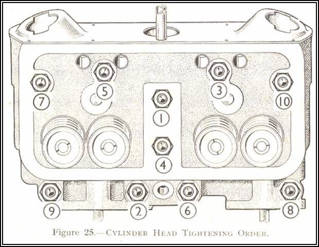
A Caution About The Oil Feed Stud –All but one of the cylinder head studs (for each head) tighten
against their thread shoulder and do not bottom in the crankcase threaded
holes. The one exception where a cylinder head stud is not threaded fully into
the crankcase is the stud, described as ‘1’ in the cylinder head tightening
sequence, which carries lubricating oil to the rocker shaft assembly. This stud
has been designed to bottom in the threaded hole and form a seal at the flared
copper oil delivery pipe, against counter bores in the crankcase set. Typically,
this stud does not screw very far into the crankcase, which raises a concern.
In the Maintenance Manual there is no mention of caution where this
stud is concerned. During the installation of the cylinder head, there should
not be a temptation to tighten the cylinder head securing nuts before
installing the rocker shaft assembly, by using a packing spacer on the oil feed
stud, to achieve even clamping of the gasket – prior to installing the rocker
shaft banjo nut with an open ended spanner. This stud has been drilled and
relieved to provide oil passage, it is also not threaded very far into the
crankcase, and for these reasons, the specified 37.5 lb.ft torque should not be
applied to this stud.
Installing Studs – Javelin and Jupiter crankcases are manufactured from aluminium. This
is a relatively soft metal and caution should be observed when installing all
studs into the crankcase, and not only the cylinder head studs. Many crankcases
have been distorted at gasket surfaces by over-tightening of studs into them.
As a stud is over-tightened, two conditions can eventuate; the female thread in
the crankcase can be distorted (pulled) to the extent that it is ‘stripped’ or,
the metal immediately around the thread shoulder of an over-tightened stud can
deform (swell). This second phenomenon can be such that the clamped component
can be held away from the mating surface of the crankcase, thus preventing
effective clamping of the gasket. It is wise to remember the 40% of nominated
torque rule.
It should be noted that Series III crankcases had cylinder head stud
threaded holes counter bored with a clearance diameter to prevent deformation.
This engineering change requires the use of longer shank cylinder head studs.
These crankcases also had small holes drilled at right angles to the outer stud
threads, at studs '8' and '9' in the tightening sequence diagram, to prevent a
‘hydraulicing’ condition as the stud is screwed into its hole.
Studs threaded into blind holes in aluminium castings should be
thoroughly cleaned and then have their threads coated with Penrite Copper-Eze
to prevent corrosion, caused by two different metals being in contact with each
other, and to permit ease of extraction next time the engine is overhauled.
In those instances where oil is likely to seep along a stud’s thread
in the crankcase, the stud should be installed using Loctite 518 Mastergasket
sealant. This will most definitely prevent oil from seeping through. If this
sealant is used, the stud should be screwed in quickly to the 40% torque value,
because of fast sealant curing. Another point to bear in mind is that, if
sealed studs require removal, application of heat will be required to soften
the sealant (unscrew the stud while the aluminium is still hot – or the sealant
will set even harder!).
Another option is to clean the cylinder head studs and their threads
in the crankcase with Loctite 471 Accelerator Cleaner fluid. Leave the cleaner
fluid to stand for twenty minutes and then install the cylinder head studs,
with Loctite 269 Studloc applied, and tighten into the crankcase to the
recommended torque. Allow the Loctite to cure, preferably overnight. Cylinder
head stud removal will require moderate heating of the aluminium prior to
removal.
Applying Loctite at the studs ensures that there is no likelihood of
a stud rotating while the cylinder head nuts are tightened.
Cylinder Liner Installation
There are four separate components that need to be taken into
account, that a cylinder head gasket has to contend with, when the cylinder
liners are installed into a Javelin/Jupiter engine. They are:
1. Cylinder liner sealing – pressures up to 180 psi (1,241 kPa), 9:1
+ compression ratio.
2. Oil sealing – pressures up to 100 psi (690 kPa).
3. Coolant sealing – pressure of 4 psi (28 kPa), and anti-freeze
self search properties.
4. Vacuum – to 22"
hg.
To guarantee gas, oil, water and vacuum tight seals at both ends,
the cylinder liners should be carefully installed as follows:
1. An
essential start to installing the cylinder heads, and their gaskets, is to
achieve the correct cylinder liner protrusion, 0.006” – 0.008” (0.15 – 0.20
mm), proud of the crankcase surface. For sealing the cylinder liners in the
crankcase, the genuine soft compound ‘Hallite’ gasket rings c/w thin shims, are
no longer used. Three thicknesses of solid copper spacers and shims are
available for adjusting the protrusion to the correct specification.
Note:
All liners will require a quantity of shims.
2. The
threads of both the studs and nuts should have been cleaned-up using a suitable
die nut and thread tap. The studs should thread freely by hand into the
crankcase and the nuts should spin freely on to the studs, without being too
loose in either case. Genuine cylinder head nuts are thicker than standard 3/8“
BSF nuts and should be lightly oiled prior to use.
There
are ½" deep 3/8" BSF nuts of high quality available, these are
0.522" AF (1/4" Whitworth spanner size) and require good quality flat
washers under them. Ideally these nuts should be used with longer cylinder head
studs.
3. Cylinder
head studs should be installed into the crankcase using Penrite Copper-Eze to
facilitate future extraction. Or, for a firmer hold of the studs, the use of
Loctite 269 Studloc is recommended.
4. Before
installing the shims so that measurements can be taken, clean the surfaces in
the crankcase where the liners seat. It is a good idea to suck away any debris
with a vacuum cleaner. Make sure that the liners are a smooth sliding fit into
the crankcase, using easy hand force. A careful rub in the crankcase bores with
fine grade wet and dry paper soaked in kerosene or Penetrene will ease this
(wash the crankcase set thoroughly after the cleaning-up process).
5. The
liners must be absolutely clean. Slide the liners into the crankcase without
any shims. Using feeler gauges, measure the gaps between the liner outer
surface and a good quality straight edge clamped to the head gasket surface. Record
the values found for each cylinder. During calculations, make sure that each
pair of liners have the same protrusion.
The
cylinder liners should be identified by numbering so that they are installed in
their selected crankcase bore. They may, initially, require swapping around to
achieve equal protrusion per pair. Once this has been established, identify
each liner according to its cylinder bore in the crankcase.
6. Select
the correct quantities of shims to provide the correct liner protrusion and
install them with the liners. Do not apply any sealant at this stage. Install
the cylinder heads minus gaskets and tighten the nuts to 10 lb.ft.
progressively to clamp the shims. The face of the cylinder head must be clean
and flat. Tighten the nuts in the correct sequence. The liner protrusion can
now be verified around the entire edge of the crankcase surface. If there is a
variance of more than 0.002” between the pair of liners check the cylinder head
surface, if this is flat the lowest liner will require extra shims to set both
liners to the same height tolerance, of 0.002”.
If
the crankcase surface is found to be severely distorted, the cylinder head
studs and the crankcase centre joint dowels will have to be removed. The
crankcase half can then be set up in a milling machine so that the minimum
amount of metal is taken off to true-up the surface. It should be noted that
the internal carburettor balance pipe protrusion will have to be machined off
during this process, and, therefore, a machined flanged bushing should be
pressed in to the balance pipe to restore its protrusion. The flange should be
pressed in with a small smear of Loctite sealant under the flange lip. The
flanged bushing should have a minimal wall thickness.
If
the crankcase has been welded, in the head gasket surface area, extreme care
should be taken during the milling process.
6. When
selecting shims to make up a shim-pack, add the individual thicknesses of the
shims (use a micrometer or an accurate vernier gauge) to obtain the correct
liner protrusion. This is very important, because if the shims are measured
together, a different value will be obtained, because the shims may not be
entirely flat after being cut from the copper sheet and it is not a good idea
to duplicate 37.5 lb.ft. with a micrometer!
7. With
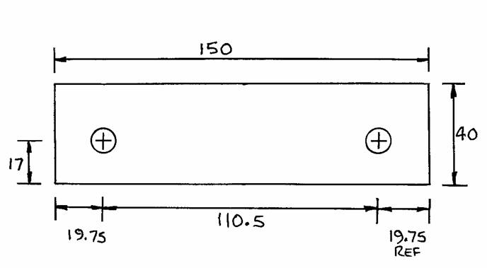
the pair of liners assembled into their crankcase half, with their shim packs,
the height of the cylinder head gasket support must be checked. The earlier
style support assembly, has a 10 SWG plate (which must be flat) and an aluminium
tube. This assembly must be adjusted so that the support is flush with the lips
of the two cylinder liners, while resting on the cylinder liner abutments. It
is preferable to place a 3/8” brass flat washer on the
tube so that it supports the cylinder head gasket over a greater area than the
relatively thin-walled tube. The tube should be machined precisely so that the
surface of the brass washer is flush with the liner lips.
The
later style cylinder head gasket support is an aluminium casting which was
shimmed at the outer end with copper shims. This casting can be precisely
machined so that, with a 3/8” brass washer installed, the
assembly is flush with the cylinder liner lips. The later style support may not
be available – if this is the case, a support assembly, the same as the early
style support can be made-up quite easily.
The
new club supplied supports are the same as the later Jowett Engineering
supplied item. However, there is one difference – the overall length is longer
and requires machining to suit the liner and shim set up. The important point
to note is that the ledge on the liner should form a part in the machining
calculation. The support casting is designed to support the cylinder head
gasket, not to forcefully clamp the cylinder liners.
8. Should
cylinder liners have been selected from unknown sources, then the radii cut
into the skirts should be checked for crankshaft and connecting rod clearance.
This advice refers particularly to cylinder liners not manufactured by Jowett
Cars Limited – i.e. non-genuine parts.
9. The
shims can be installed dry, providing surfaces at crankcase and liners are in
good condition. If there is any doubt, a light smear of Loctite 518 sealant can
be used, only on the shim surface that contacts either the liner or the crankcase.
It must be noted that Loctite 518 (and other sealants) will build-up after
curing, and this condition must be taken into consideration when maintaining
liner protrusion. The specified cylinder head nut torque value will not
compress the cured sealant film.
If
Loctite 518 sealant is used, the pairs of liners will have to be clamped into
the crankcase quickly and evenly. Use sealant only on the shim surfaces that
contact the liner and crankcase, the intermediate surfaces will form a good
seal. All shim surfaces must be clean.
To slow the sealant
curing time, wash the contact surfaces with methylated spirits – do not use the
Loctite 471 Cleaner Accelerator fluid.
10. Insert
the liners and their shim-packs into the crankcase in pairs, making sure that
the cylinder head gasket support is also installed at the same time.
It is a good idea to
apply a smear of engine oil to the bores in the crankcase, not on the liners,
to ease assembly.
Cylinder Head Gasket Installation
Cylinder Head Gasket Background – Since the late 1960s, the Jowett Car Club of New Zealand have been
involved with cylinder head gasket manufacture. This was initiated by Leao
Padman who required specially made gaskets because he was using larger diameter
pistons – up to 76.3 mm (3.004") – and required a gasket with a larger
bore. He experimented with various engines, using different cylinder head nut
torques, some as low as 25 lb.ft, and with various materials. The gasket
material finally chosen was Reinz, and the gasket design was the same as that
used today. The material was of a wire mesh impregnated with compressed
asbestos fibre both sides of the mesh, with the copper on the one side. This
made a gasket suitable for the higher compression when using flat top pistons
(9.25:1). The copper/asbestos/steel gaskets for higher compression ratios, at
that time, were still available from the NZ Jowett spares supplier.
By the 1980s, however, the copper/asbestos/steel gaskets were
running out, so the New Zealand club had a gasket die made at the same firm as
Leao Padman had used in Auckland, but with a standard bore for pistons up to 75
mm (2.93") diameter. They still used the Reinz material and, on low
compression engines, one-stepped torquing was probably adequate as the Reinz
material wasn't as soft as the original copper/asbestos/copper gaskets and the
0.006" - 0.008" (0.15 – 0.20 mm) cylinder liner protrusion was specified.
Neil Moore wrote a technical article in 1993 about setting cylinder liner
height with solid copper spacers and shims and mentioned the above about
torquing the cylinder head nuts. Somewhere in the repeats of his original text,
the term 'Monotorque' surfaced. Payen, in New Zealand do manufacture a type of
gasket that is called 'Monotorque', and has absolutely nothing to do with the
cylinder head gaskets supplied by Jowett Spares (NZ).
In about 1998, the gasket supplier informed Jowett Spares that the
Reinz material was no longer available because of global health concerns about
asbestos, Thus an alternative had to be found. This is the grey material
currently used, which is a cellulose product impregnated on a perforated steel
middle sheet – both sides. This material is softer than the Reinz material, but
is 0.010" (0.254 mm) thicker. The initial recommendation from the gasket
supplier was for Jowett Spares to experiment, but considered that a hot
tightening of the cylinder head nuts would be satisfactory.
The new-material gaskets were tested in a Jupiter used for racing.
This engine was equipped with flat top pistons, providing 9.25:1 compression
ratio, from a R1 Jupiter engine. Thus it was a fairly severe test over some
three or four years. The original 0.006" – 0.008" (0.15 – 0.20 mm)
cylinder liner protrusion specification was adhered to, and the gaskets were
tried with one tightening over, say, five times at 20 lb.ft to settle the
gasket, and a couple each at 28 lb.ft and 33 lb.ft and finally at 37.5 lb.ft..
After this procedure had been used for about one year, water leaked. So the
next installation was given the same treatment as previously, but when the
engine was hot and re-torqued to 37.5 lb.ft a further increase of tightening
was observed as the gasket squeezed home.
The tappets were adjusted with the engine cold, the next day. This
installation was used for racing and towing until further mechanical problems
surfaced and cylinder head gaskets, when removed, were found to be in good condition.
The squashed thickness was the same as the Reinz material. Thus the desired
result was achieved.
Installing The Cylinder Head Gaskets – Careful
installation of the cylinder head gaskets is of paramount importance. The
surfaces of the cylinder heads and crankcase must be absolutely clean.
1. First,
install the coolant water inlet elbows,20826 and 50829, with their gaskets and
tighten. Apply a smear of Loctite 518 to both metal surfaces. Installing the
inlet elbows at this stage provides extra support, at the rear of the crankcase
assembly, during the cylinder head tightening process.
2. The
head gaskets received from New Zealand, are of more modern material than the
Jowett Cars Limited's original copper/asbestos/copper (or the higher
compression copper/asbestos/steel type) gaskets. They are definitely not
‘Mono-torque’ gaskets
These
modern gaskets are softer and thicker in their composition, but, a word of
caution – they may not completely conform to severe depressions in the
crankcase surface. Therefore coolant leakage could occur at the outer edges of
the crankcase.
The
current style cylinder head gasket has provision for placement of an ‘O’ ring
at the oil feed stud. The ‘O’ ring seals oil, at engine oil pressure, from
forcing its way into the engine’s coolant. The 'O' ring should be slid over the
oil feed stud after the gasket has been placed into position.
The
surfaces of the cylinder head gaskets that contact the head and crankcase
should be carefully wiped with a clean cloth dipped in methylated spirits. A
light smear of Loctite 518 Mastergasket should be applied only to edge of
gasket and crankcase to assist in preventing coolant seepage.
Do
not apply Loctite 518 Mastergasket to the cylinder liner-to-head seal faces.
Be
extremely careful not to obstruct the oil drain holes in the crankcase.
3. The
washers at studs numbered 3, 5, 7 and 10 (see front cover of these notes) in
the Maintenance Manual, have the smaller outside diameter flat washer. The
remaining studs all have the large outside diameter flat washer. Stud identified
number ‘1’ has one fibre washer between the cylinder head surface and the rocker
oil feed banjo, there is another fibre washer on top of the banjo and then
there is a large outside diameter steel washer below the nut. The cylinder head
stud flat washers are close tolerance washers. Stud number ‘4’ has a square section
rubber ring.
When
installing the rubber ring the recess in the outer cylinder head face and the
cylinder head stud must be absolutely clean and free of oil. The water seal
rubber washer is then slid over the stud and pushed firmly into the recess.
Apply a small bead of Loctite 518 sealant around the cylinder head stud
adjacent to the seal rubber. Next, install the plain washer, Part No. 52193-SM,
and push it into the seal recess. This washer is followed by the larger outside
diameter plain washer, Part No. 52193-LG, and the cylinder head nut. The
smaller diameter washer compresses the seal further into its recess than would
be the case if a large diameter washer only was employed.
4. Provided
the stud threads, nuts and washers are a good fit and the head is tightened on
to the crankcase progressively, in three tension stages 20 lb.ft three times,
30 lb.ft two times and 37.5 lb.ft two times, following the stud sequence as
shown in the Jowett Maintenance Manual (remembering that nut # 1 is the oil
feed stud), the cylinder head gasket installation should be successful. The
thread in the cylinder head nuts should be lightly oiled. It is also advisable
to use a 3/8“ square drive socket because of the limited
clearances around the nuts. A torque wrench with the specified final torque
value at its mid-range point should be used.
5. It
is important that the five upper studs numbered, 3, 4, 5, 7 and 10, in the
Maintenance Manual, on each cylinder head, are sealed. Cooling water can
migrate along these studs and drip into the rocker cover, and thence drain to
the engine oil sump. Most commonly, coolant can migrate along the stud
identified as number ‘4’.
The original method was
to use very fine solder or strands of lead wool wound round the studs and then
the nut and flat washer were tightened squeezing the lead into the threads and
the clearance between the studs and the head. Another method is to use a fine
bead of Loctite 518 Mastergasket sealant around the stud thread prior to
installing the washers and tightening the nuts. This method is probably less
likely to distort the tensioning results. Excess sealant must be cleaned up
immediately after tightening the nuts. Do not allow any sealant to reach the
engine’s oil pump – pieces of sealant can severely restrict oil flow at the oil
pump pick-up gauze strainer.
6. Tighten
the cylinder head nuts, in the correct sequence, in the stages described at
Item 4 to 37.5 lb.ft. (50 Nm). The tensioning must be slow and steady, a
jerking action can give an incorrect tension. Use a good quality torque wrench
of reputable brand with known tolerance characteristics.
Note
that at stud ‘1’, suitable spacers can be used under the nut and washer, so
that a moderate clamp force can be initiated on the gasket. Do not apply the
total specified torque at this stud.
7. After
tightening the cylinder head nuts, and before the engine oil sump has been
installed, use a suitable stiff wire to clean the two oil drain holes in each
cylinder head. Wipe away any excess sealant that has been forced through by the
wire.
8. Following
the assembly of the rest of the components, the engine should be run until it
has stabilised at 75 ºC (operating temperature).
Switch off the engine
once this condition has been achieved, the cylinder head nuts must be
re-torqued after the engine has stabilised for a twenty minute period after
switching off.
9. Original
style Jowett cylinder head gaskets should be installed using the same procedure
as outlined for the current gaskets. It is important to note that, with these
gaskets, the cylinder head nuts require re-tensioning when the engine coolant
has stabilised at operating temperature, 75 ºC.
Adopting the aforementioned procedure will ensure successful
installation of cylinder head gaskets.
Use the Maintenance Manual to assist with further assembly of the
engine.
A Tip On Stopping Coolant Seepage
Sometimes, after the most conscientious assembly process and no
matter what type of gasket sealant has been used, coolant water seepage can
occur. In such an instance, we can take a comment out of the Jaguar V12 service
manual. Such an engine, basically aluminium in tis construction, has a myriad
of joints that have to keep the coolant inside at 12 – 15 psi (83 – 103 kPa)
inside its proper places. The service manual for that engine instructs the assembler
to add a bottle of Bars Leaks to the coolant. This is not just recommended, but
is an actual assembly instruction.
In the past, where slight coolant seepage has occurred after
assembling a Jowett engine, the use of half a bottle of Wynn's Radiator Stop
Leak, a blue liquid in a 325 ml bottle, has been entirely successful. Run
the engine for about ten minutes and this chemical will stop the seepage. It
will not clog the radiator and it mixes happily with anti-freeze
Engine Coolant Maintenance
The owners’ handbooks for Javelin and Jupiter cars do not provide
pertinent information about maintaining the cooling system. They do, however,
mention adding antifreeze mixture – which in most of Australia would have been
disregarded due to our warm climate. To preserve vital components of the engine
which come into contact with the coolant, a suitable corrosion inhibitor must
be used. When the cars were built, no one considered that, in over fifty years
time, the cars would be preserved and still in use. Hence no mention of the importance
of using soft water and a corrosion inhibitor to protect against cavitation
erosion and electrolytic corrosion, due to the use of dissimilar metals to make
up the cooling system – i.e. cast iron, steel, aluminium, brass, copper and
solder (lead and tin). Water, depending on its chemical make-up, when in
contact with these different metals, can be the instigator of electrolytic corrosion,
particularly when cast iron and aluminium are in close proximity to each other.
It should be noted that the process of electrolytic corrosion does
not only take place while the engine is running – it is active at all times.
There is a very simple solution to this problem. It is a maintenance
programme which ensures that the engine cooling system is filled, and
maintained, with a good quality corrosion inhibitor such as Tectaloy Xtra
Cool Gold. One litre of this product will make-up fifteen litres of
coolant. It is suitable for three years use in the cooling system. Another
approach is to use coolant made-up from 10% Ford R1-3B corrosion inhibitor and
90% soft water or, use a brand of inhibitor that meets AS 2108-1977 and
contains 18% ethylene glycol. If antifreeze is required the make-up should be
50% Castrol Antifreeze/Anti-boil Concentrate (Ethylene Glycol 95% mass, to AS
2108-84) and 50% soft water.
The cooling system must be drained, flushed and filled with a
fresh mix of corrosion inhibitor or antifreeze at two or three year intervals.
Top-up coolant must be pre-mixed as indicated above. Use corrosion inhibitor
when temperature does not drop below 0 ºC. Remember the ‘cold night chill
factor’ when making a decision.
Extreme care has to be taken when making up the mixture – if too
weak, the cast iron, steel and aluminium components will corrode – if too
strong, brass, copper, solder and rubber hoses will be damaged. The coolant
passes through tracts within the crankcase and timing cover which are made from
aluminium, consideration must be given to preventing corrosion of these components,
which can be severe enough to allow water to pass through into the engine sump
and contaminate engine components. If the coolant mix is too strong, the solder
in the radiator can be affected to the extent that ‘solder bloom’ can (in
severe cases) cause partial radiator core blockage, leading directly to an
engine overheating condition.
Do not top up the radiator each time the vehicle is used, the
coolant level will soon settle and the practice of topping-up should be
minimal. When the engine is cold the radiator should not be full of coolant to
the overflow outlet, the level should be ½“ to ¾“ below the overflow outlet. As
the engine warms up, the level in the radiator will rise.
Inhibitors to AS 2108 provide further protection than preventing a
corroded or frozen system – they prevent erosion of the cylinder liners due to
cavitation-erosion (liner flexing – induction, compression, combustion and
exhaust cycles), this condition can lead to the generation of tiny bubbles
which implode against the cylinder liners (usually on the thrust side) and
slowly eat away the liner surface. This concern would be most commonly found
with the early thin wall section liners. Corrosion inhibitors also prevent the
build-up of calcium scale which can cause localised overheating of the liner
wall and, ultimately, local pick-up of piston material within the cylinder
bore.
Failure to change the coolant mix regularly can result in
overheating concerns due to the coolant settling and forming a jelly-like
substance. It can also corrode aluminium components if they are dry. This is particularly
so if the engine is not run frequently. Ideally the hoses should be changed at
the same time as the coolant. Condition of all hoses should be carefully monitored.
A hose in good condition is firm, but evenly supple. A hose in poor condition
is either very soft (too strong a corrosion inhibitor mix) or very hard (due to
lack of use and age). Good quality, genuine style, hoses are now available from
the club’s spares stock.
An antifreeze mixture has a ‘self searching’ property and will find
any weakness that may be present at gaskets and hose joints. Any leaks found
should be repaired quickly. Leaking antifreeze, when it meets the atmosphere,
will corrode aluminium and steel components. Do not store the car for lengthy
periods with a drained cooling system. Tectaloy Xtra Cool Gold can be
left in a stored car's cooling system for many years, it has been found to be
in good condition after nine years of storage.
There have been cases where, if engine oil infused with the coolant,
liquid detergent was used to disperse the oil in the system. It is not a good
idea to use a detergent for this purpose, because it can be very corrosive to
aluminium, In those cases where soap detergent has been used in an engine's
cooling system, should the system be drained in preparation for engine storage,
then it should be thoroughly flushed out using clean water. If there is any
trace of detergent within the system after it has been drained, it will cause
problems of severe corrosion of metal components and hardening of hoses.
The same warning applies if cooling system cleaning chemicals have
been used to flush the system.