TECHNICAL NOTES SERIES
JOWETT JAVELIN – PA, PB, PC, PD & PE
JOWETT JUPITER – SA & SC
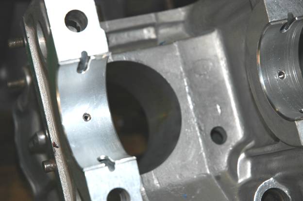
.An Alutin bearing shell installed on a Javelin front main bearing
support.
PART VI – ALUMINIUM-TIN BEARINGS
ACKNOWLEDGEMENT
Our thanks to the Glacier Bearing Co. and to the late John Taylor
who took the trouble to keep this information for our club. It was typed into
Word 2003 from a faint photocopy by Mike Allfrey.
The Jowett Car Club of Australia Incorporated is not responsible for
any inaccuracies or changes that may occur within this document. Every effort
has been made to ensure total accuracy. It is not a Jowett Car Club publication
and, therefore, the Club has no control over its contents. These Technical
Notes have been compiled by using the latest information available.
Compiled by Mike Allfrey – January, 2007.
ALUMINIUM ALLOY BEARINGS
History Of The Development Of
Reticular Aluminium-Tin Steel Backed Plain Bearings
From the
Automobile Engineer, June 1958 – Reprinted by The Glacier Metal Co. Ltd.
For some years, aluminium alloys have
been used for crankshaft main and big end bearings. In England considerable experience has been gained in the use of bearings of aluminium alloyed with
5-7 per cent tin, without steel backings, in diesel and petrol engines. These
alloys, which were introduced in about 1936, initially showed great promise in
that their frictional and wear characteristics appeared to be considerably
better than those obtained with any previously used aluminium alloys. Indeed,
in some cases they were used on soft shafts, seemingly without trouble. They
were adopted by one or two important manufacturers of diesel engines who used
them fairly extensively. Gradually, however, troubles began to develop. Occasionally
there were seizures of a very serious nature, resulting in considerable damage
to the engine. Experience also showed that the yield strength of these alloys
was insufficient to enable bearings to maintain an adequate interference fit in
main bearing housings and connecting rods. There were cases of dowel holes
gradually being elongated until location of the bearing was lost to such a
degree that oil feed holes were throttled. One manufacturer, who had used these
bearings extensively, had to replace all of them with a different type.
Extensive experience showed that this aluminium alloy containing 5-7
per cent tin was not satisfactory as a compromise between the two opposing
requirements. These requirements are: low wear characteristics, which call for
additions of tin or other low melting point metal; and higher strength, which
can only be achieved by reducing the tin content. It became clear that one
solution might well be along the lines of a considerable increase of tin
content, to improve the anti-scuffing characteristics, and the bonding of this
high tin alloy to a steel backing to increase the strength of the bearing.
A great deal of work has been done in the United States with steel
backed aluminium alloy bearings, and these have been used extensively for many
years by one very large firm of diesel engine manufacturers. The alloy employed
contains 6 per cent tin; however, success has only been achieved at the expense
of hardening the crankshafts and by the maintenance of unusually rigid
discipline with regard to limits, finish, cleanliness of the engine, etc. Even
with such an approach, many diesel engine manufacturers have been unable to
obtain satisfactory results in the use of alloys of this nature. One
manufacturer in the United States has produced steel backed bearings lined with
an aluminium alloy containing a small percentage of cadmium. However, this
alloy is not wholly satisfactory as a bearing surface, so it is generally given
an electro-deposited lead-tin overlay. In these circumstances, the aluminium
alloy is not the bearing surface, but merely an interlayer.
So far as the history of aluminium bearings in other parts of the
world is concerned, the trends already outlined were also experienced by more
or less independent operators in England and in Germany, as well as in the United States of America. EW Hives and F Llewellyn-Smith in the SAE Journal of
December 1940 stated that Rolls-Royce car and aircraft engine big end bearings
were of aluminium-based alloys containing 5-7 per cent tin, but lead-bronze was
employed in the Rolls-Royce Merlin engines; the use of aluminium alloyed with
5-7 per cent tin for bearings was substantially limited to a car engine. The
Rolls-Royce patent number 426211,dated 29th March, 1935, included a
range of tin content from 8-19 per cent, but it is known that as-cast alloys
containing over 10 per cent of tin are weak because the aluminium phase is
discontinuous. Moreover, owing to the very rapid formation of brittle
aluminium-iron compounds, the casting of the aluminium-tin alloy on to steel is
not suitable for the manufacture of these bearings.
In the United States, Hunsicker, of the Aluminium Company of
America, said that it was evident from extensive research that 20-30 per cent
of tin was desirable in the aluminium, in order to obtain adequate anti-scuffing
properties with cast alloys, but that the mechanical requirements of most
bearings placed an upper limit of about 10 percent on the tin content of such
alloys. As a result of the research, a series of well known alloys of high
fatigue strength was developed, but these alloys were highly sensitive to dirt
in the oil. The report on this work, entitled 'Aluminium Alloy Bearings –
Metallurgy, Design and Service Characteristics', was published in the Journal
of the American Society of Metals, 1949.
From 1932 to 1943, development work with various tin-free or low-tin
content aluminium-based alloys was carried out in Germany by the Karl Schmidt
Company. In a report by Dr. Ing. Carl Englisch, experience similar to that of
Hunsicker is described. Bench tests gave satisfactory and encouraging results,
but road tests sooner or later showed failure by gross scuffing and seizure. These
tests also indicated that these bearings were excessively sensitive to external
influences and that their successful use, in any case, would depend on a high
standard of lubrication. This report is available as one of the Document
Reprints of the Air Documents Division of Headquarters of Air Materiel Command,
Wright Field, Daytona, Ohio. The reference number is MX1191 US Army Air Force
Card Index (German Technology ADRC).
Steel Backed, High Tin Content, Aluminium Alloy Bearings
It can be seen that two problems had to be solved before the full
advantages of aluminium-tin alloys could be obtained. The first was the
production of a high-tin aluminium alloy in which, to get maximum strength, the
aluminium phase was continuous. Secondly, it was necessary to bond this alloy
to a steel backing, without forming excessive aluminium-iron compound.
Of these two problems, the first was overcome as a result of work
sponsored by The Tin Research Institute, at the Fulmer Research Laboratories.
The second was solved jointly by The Tin Research Institute and the Glacier
Metal Co. Ltd.; this was done some three years ago. During 1956, Glacier
developed from a pilot plant a small production plant for making composite
aluminium-tin-on-steel strip. This plant has been operating continuously for
the last eighteen months. It is capable of making bi-metallic strip up to
0.10" (2.54 mm) thick, that is, a thickness adequate for the bearings of
most engines developing up to about 200 bhp. A major production plant, having a
capacity to make bi-metallic strip up to 0.20" (5.08 mm) thick is now in operation,
so material is also available for the manufacture of bearings for large diesel
engines designed for a wide range of different applications.
Conditions of Operation
The conditions of operation of journals in lubricated bearings may
be classified as follows:
- Hydrodynamic – where oil is available at the entry to the converging
region of the clearance space.
- Hydrostatic – where oil is supplied at pressures exceeding the
specific load on the bearing in the appropriate region.
- Boundary – where the journal and bearing metal surfaces are
separated by very thin films of oil, which are attached chemically to the
journal and/or bearing metal or oxide surfaces.
- Break-down – where the journal and bearing metal surfaces are
in contact.
As regards hydrodynamic and hydrostatic
conditions, the only property required of the bearing metal is strength to
withstand the applied loads. That is, once the hydrodynamic film between the
journal and the bearing is established, the surface properties of the journal
and bearing metals are immaterial. Softness of the metal, however, aids the
formation of hydrodynamic films, as do to a lesser extent certain other surface
properties.
It is with regard to boundary and break-down conditions that the
surface properties of journal and bearing metals become of paramount importance
and, as practically all journals and bearings have to operate at some time or
other under these conditions, the metals must be appropriately chosen with
regard to their compatibility in these circumstances.
To operate under boundary conditions, the metal surfaces must be
more than merely wetted by the lubricant: at least one of the surfaces must
bond chemically to oily radical constituents in the lubricant, to form a
molecular layer; moreover, should the layer be damaged as a result of
metal-to-metal contact, it must be capable of being healed automatically. On
evidence at present available, bearings alloys with a high free energy of oxide
formation are more likely to be better in this respect than those that have a
low free energy of oxide formation. Since the journal is usually of steel, the
requisite properties must generally be inherent in the bearing alloy.
Operation under break-down conditions is essentially of very short
duration and inevitably modifies at least one of the sliding surfaces. The
modification to one of the surfaces during breakdown conditions must be such as
rapidly to alter the conditions so as to prevent significant damage to either
of the two surfaces involved. Bowden has shown that when two metals are in
sliding contact, the temperature reached is the melting point of the phase
having the lowest melting point, and if this is substantially lower in one of
the surfaces than the other, the effect for short periods is immediately to
relieve high local specific loads and to prevent gross damage. Since the
temperatures of sliding contact are so high, the metal constituents of the bearing
alloy should not be prone to penetration of the journal material.
Bowden has also demonstrated that in the case of a multi-phase
material where one of the phases is fairly soft and has a relatively low
melting point, the coefficient of friction is low and the effect in
metal-to-metal sliding contact is to inhibit the occurrence of further damage.
Hence, two-phase materials, in which one of the phases is soft and of low
melting point, are advantageous as bearing surfaces.
Comparison with Other Bearing Alloys
Since no material yet discovered is perfect in all respects, a
compromise is unavoidable. Reticular aluminium-tin on a steel backing has a
high fatigue strength and has relatively good anti-scuffing properties, as compared
with other known bearing metals of high fatigue strength.
The conventional white metal bearing alloys are not strong enough to
meet many present-day requirements, and the most commonly used alternative is
copper-lead. This is a two-phase material, but has a number of disadvantages.
First, the copper phase has a high melting point and is rather hard. This leads
to a high rate of journal wear, unless the journals are hardened. Unfortunately,
the hardening process is usually expensive. Secondly, copper penetrates steel
very rapidly and can cause shaft embrittlement, and there is a possibility of
shaft breakage if any substantial or prolonged metal-to-metal contact occurs.
The third defect is that, with certain modern oils, copper-lead is susceptible
to corrosion, especially in engines where high sulphur content fuels are used.
Copper also acts as a catalyst in the break-down of certain constituents of
modern high-duty oils.
Table 1 summarises the relative merits of conventional bearing
alloys or composites, and some aluminium alloys, including reticular
aluminium-20 per cent tin. Table 2 gives the comparative fatigue strength and
wear data of the various materials.
The use of three-layer bearings, in their necessarily pre-finished
condition, for mass produced small diesel engines is a practice that is now
well within the compass of modern technology. For large diesel engines, this
still represents serious difficulties when the number of engines of a
particular type produced is small. Aluminium-tin bearings, on the other hand,
are capable of being bored in position in the engine, and this practice enables
the necessary degree of accuracy on assembly to be more easily obtained. Plants
now being built will enable bearings of aluminium-tin on steel to be produced
at lower cost than the three-layer bearings. This reduction in cost is possible
because of the lower cost of the alloys used, the elimination of overlay
plating, and the speedy and controllable nature of the process used in the production
of aluminium-tin bearings.
Although bearings of reticular aluminium, alloyed with 20 per cent
tin, and steel backed, are relatively new, they have been applied successfully
as original equipment to a wide variety of engines produced in both small and
large quantities. Thus, the experimental results have been confirmed by the
fact that hundreds of thousands of engine bearings made by The Glacier Metal
Company Ltd are operating satisfactorily in service not only in Great Britain
but also abroad.
TABLE 1
CHARACTERISTICS OF VARIOUS BEARING
MATERIALS
|
Running Conditions
|
|
Material
|
Hydrodynamic
1. Strength
to withstand load. The ratio of fatigue strength relative to tin-base white
metal, 0.015" to 0.020" thick, is shown in brackets.
2. Softness
to initiate and maintain oil film.
|
Boundary
1. Surface wettable
by oil.
2. Chemical
affinity for molecular layer of oily radical constituents.
|
Break-Down
1. Surface to
have a low melting point phase.
2. The low
melting point phase not to work harden and to be softer than the matrix.
3. Effect of
2-minute oil supply failure.
|
Environment
1. Bearing
metal constituents must not be prone to grain boundary penetration in steel
at their melting points.
2. Must not
cause catalytic break-down of oil.
3. Must
resist corrosion.
|
Remarks
|
|
Tin-based and
lead-based white metals
|
1. Usefulness
limited unless bonded in a very thin layer to steel. (Unity)
2. Very good.
|
1. Good.
2.Tin-base
white metal fair; lead-base white metal good.
|
1. The whole
alloy has a low melting point.
2. The matrix
has a lower melting point and is softer than the discontinuous phases.
3. Surface
wipes and lining runs.
|
1. Good.
2. Good.
3. Tin-base
white metal good; lead-base white metal fair.
|
The main
defect of white metal is its inadequate strength for many modern applications.
|
|
Copper-lead
|
1. Good when
bonded to steel (1.7 for copper-lead 70/30).
2. Poor to
fair according to lead content.
|
1. Good.
2. Fair.
|
1. Good.
2. Good.
3. Very high
surface temperatures develop.
|
1. Poor.
2. Poor.
3. Poor.
|
Copper-lead
is a good bearing material, by and large, but is a little too hard for use universally
with soft crankshafts, and is susceptible to failure in certain environments,
for example, severe edge loading.
|
|
Copper-lead
with overlay of lead-based alloy.
|
1. Good when
bonded to steel (1.5 to 2.0 depending on thinness of overlay).
2. Good.
|
1. Good.
2. Good.
|
1. The whole
of the surface alloy has a low melting point.
2. The matrix
has a lower melting point and is softer than the discontinuous phases.
3. Overlay
wipes.
|
1. Good so
long as overlay lasts.
2. Ditto.
3. Good in
the presence of corrosion inhibitors, such as tin or indium, in the lead.
|
If there is
cavitation in the oil film, overlays occasionally wear or fatigue and leave a
bare copper-lead surface with poor accommodation in many environments.
|
|
Aluminium-silicon
|
1. Good
(2.0-3.0+)*
2. Fair.
|
1. Good.
2. Good.
|
1. Poor.
2. Poor.
3. Is likely
to seize.
|
1. Good.
2. Good.
3. Good.
|
Aluminium-silicon
is a good bearing material, except for its deficiencies in properties
required for break-down conditions of operation. It is usually provided with
a tin- or lead-based overlay.
|
|
Aluminium 6-9
per cent tin
|
1. Good when
bonded to steel. (2.0-3.0+)*
2. Fair.
|
1. Good.
2. Good.
|
1. Fair; the
amount of the low melting point phase is marginal.
2. Fair.
3. Is likely
to seize.
|
1. Good.
2. Good.
3. Good.
|
The aluminium
6-9 per cent alloys are reasonably good, but the conditions of assembly and
the standards of machining of both the journal and bearing surfaces have to
be very good in order to overcome the defect of inadequate low melting point
phase. For this reason they are probably unsuitable for large engines.
|
|
Aluminium 20
per cent tin, reticular structure.
|
1. Good when
bonded to steel (2.0 to 2.5 +)*.
2. Good.
|
1. Good.
2. Good.
|
1. Good.
2. Good.
3. Moderate
surface temperatures but no seizure or serious change in dimension.
|
1. Good.
2. Good.
3. Good.
|
Reticular
aluminium 20 per cent tin can operate at much higher loads than white metal
on a soft shaft, without the degree of journal wear that is experienced when
copper-lead is used. Reticular aluminium 20 per cent tin also operates at
surface temperatures that would cause white metal bearings to wipe, or would
remove the overlay of plated copper-lead bearings.
|
* The upper limits of fatigue
strength of the three aluminium alloys referred to have not yet been
established. The figures relate to values obtained to date.
TABLE 2
COMPARATIVE FATIGUE STRENGTH AND WEAR DATA OF VARIOUS
BEARING MATERIALS
|
Aspect
|
Reticular Aluminium-Tin on Steel
|
Other Current Bearing Materials
|
|
Fatigue:
Reference Conditions:
Average surface temperature 100 degrees C.
Shaft slope approximately 0.15 per cent.
Peak load 3,000 psi (0000 kPa)
Lining thickness 0.015" – 0.020" (0.38 – 0.51 mm).
Maximum lining thickness 0.007" (0.18 mm)
|
Permissible stress at 100 degrees C is 4,000 psi on projected area.
The effect of rise of temperature is low compared with its effect on white
metal. At 150 degrees C the fatigue strength is at least 3,500 psi.
Reduction of the thickness of the lining increases fatigue strength,
but not so sharply as with low melting point alloys. At 0.007" (0.18 mm)
thick, the fatigue strength is over 5,000 psi under reference conditions.
Thinner linings have not yet been assessed.
|
White metal: Permissible stress 3,000 psi at 100 degrees C, falling to
about 1,500 psi at 150 degrees C.
70/30 Copper-lead: 3,500 psi falling to
about 3,000 psi at 150 degrees C.
Reduction of thickness of lining to 0.007" (0.18 mm) increases
fatigue strength of white metal to about 2,400 psi; at 0.004" (0.11 mm)
the fatigue strength is about 3,000 psi.
Fatigue strength of 70/30 copper-lead is also increased by reduction
of thickness and is about 4,000 psi at 0.007" (0.18 mm). Thinner linings
have not been assessed.
|
|
Wear:
The data are in terms of journal wear, expressed relative to operation
with tin-base white metal.
|
1.6 times that experienced on shaft running on white metal.*
|
70/30 Copper-lead: 2.3 times that obtained with white metal.
Copper-lead with 90 per cent lead and 10 per cent tin overlay not less
than 0.001" (0.0254 mm) thick: 0.9 times that with white metal.
Aluminium-6 per cent tin-1 per cent copper-1 per cent nickel: 2.2
times that with white metal.
|
|
Material Compatibility:
Resistance to seizure or inter-penetration with journal material if
oil supply fails.
|
Aluminium will not penetrate intercrystalline boundaries of steel
because its melting point, 660 degrees C, is less than the critical change
temperature, of 768 degrees C, for steel. The high tin content, 20 percent,
of reticular aluminium-tin alleviates the conditions where local surface
damage is initiated in the event of oil failure.
|
Copper, at its melting point of 1,083 degrees C, penetrates the
intercrystalline boundaries of steel in fractions of a second. This can cause
crankshaft failure.
The lead in copper-lead alleviates the conditions at local surface
damage areas, but cannot in the long run prevent copper penetration; nor can
a lead-tin overlay do so.
|
* These figures are based on tests in motor
vehicles with shafts of hardness averaging about 200BHN. In more than 100
engine tests, it has been shown that the wear that takes place in the first 300
miles accounts for more than half the total wear in 3,000 miles. This is
because the detritus produced in the engine and permitted to come down from the
combustion chambers past the piston rings in the first 300 miles is very much
larger in size than thereafter, when the controlling surfaces have been run in.
with soft shafts, typical wear figures in long stroke engines are in the order
of 0.0005" (0.013 mm) after 1,000 miles; 0.0008: (0.020 mm) after 11,000
miles and 0.0012: (0.0302 mm) after 33,000 miles. In engines where the bore
stroke ratio approaches or exceeds unity, the wear rates are very much less
than those quoted, and are in the order of 0.0001" (0.0025 mm) per 10,000
miles after the first 1,000 miles. With hardened shafts, the rates of wear are
almost negligible, except in the most severe environments, such as with
earthmoving equipment without adequate control of dust entry to the engine.
From The Automobile Engineer – with thanks.
GLACIER
20% ALUMINIUM-TIN BEARINGS FOR AUTOMOTIVE ENGINES
Introduction
Glacier 20% reticular aluminium-tin engine bearing material has been
developed in recent years (approx 1967) by the Glacier Metal Company as a less
expensive and in some cases superior alternative to trimetal copper-lead material
for heavy duty main and connecting rod applications in high performance petrol
engines and high speed truck diesels. Glacier 20% reticular aluminium-tin is a
high strength homogeneous material with surface properties proved to be
acceptable in engine types varying from small high speed petrol passenger car
units (1 litre, 60 cu. Ins. capacity) to diesel truck units (11 litres, 670 cu.
Ins. capacity). It is used for both connecting rod and main bearings and
against crankshafts varying in hardness from 200 Brinell upwards. It is
successfully used against both steel and nodular iron crankshafts.
In Europe, as engine speeds and outputs rise, increasingly large
quantities of Glacier reticular aluminium-tin bearings are used. In the United Kingdom alone the four major automotive companies, BMC, Ford, Vauxhall and Rootes,
together with commercial vehicle and other engine manufacturers, have fitted
Glacier reticular aluminium-tin bearings to nearly 6,000,000 engines up to mid
1967.
Engine development in Europe is proceeding along a path which, in a
broad sense, imposes two quite different operating conditions upon the
connecting rod and main bearings.
The first condition is to be found in diesel engines which are
highly rated either by means of turbo-charging, or by a sophisticated method of
supercharging. Connecting rod bearings are subjected to a very high gas load
often at low engine speeds and in such conditions the fatigue strength of the
bearing material is critical. The peak unit load on the bearing, although of
comparatively short duration, can be as high as 8,000 psi (55,160 kPa) and
10,000 psi (68,950 kPa) is under consideration. Glacier reticular aluminium-tin
bearings are used in these engines.
The second condition is found in high speed petrol engines used in
passenger cars. An engine of this type when used at high speeds, say up to
6,000 erpm for long periods at sump oil temperatures in excess of 120 degrees
Centigrade (250 degrees Fahrenheit) imposes a particularly severe bearing
condition. The load is inertia inspired and although of a reduced magnitude
compared with the first condition, say 5,000 psi (34,475 kPa), the load
duration relative to the combustion cycle is extended. Extremely thin
hydrodynamic oil films are generated and in such conditions, in addition to
high strength, very good bearing surface properties are needed if acceptable
bearing performance is to be achieved. Glacier reticular aluminium-tin bearings
are fitted to these engines and perform with equal success.
The specifications of a selection of current production engines to
which Glacier reticular aluminium-tin connecting rod bearings are fitted are
shown in Tables 1 and 2 on Page ??.
General Requirements of a Bearing Material
The increase in the specific power output of internal combustion
engines of all sizes has been spectacular in the last thirty years.
Developments in materials, metallurgy, fuels and in the thermodynamic design of
engines have been applied to increase the power obtained from a given size and
weight of engine. This increase in engine ratings has been in part contributed
to, and has in part required changes in the materials used for engine bearings.
Glacier 20% reticular aluminium-tin bearings have been developed to satisfy, as
far as any material can, the requirements of a bearing material for the engines
of today.
The properties required of an ideal bearing material may be summarised
as follows:
1. High
mechanical strength to resist the high, fluctuating pressures in the lubricant
film.
2. High
melting point to resist damage by high temperature lubricant film.
3. High
resistance to corrosion to resist attack from degraded and acidic lubricants.
4. Good
embeddability to absorb dirt passing through the bearing and prevent scoring at
high loads.
5. Good
conformability to yield easily when mating shaft is misaligned or misshapen.
6. Sufficient
hardness to resist abrasive wear and to resist cavitation erosion.
7. Excellent
boundary properties to resist seizure when the bearing is loaded but when
speeds are not high enough to provide thick, hydrodynamic films.
It is doubtful whether it would be
possible to provide a material that has all these desirable qualities but any
plans for developing a new bearing material must be made with these factors in
mind. For a particular application, it is possible to ascribe physical values
to all these properties. Mechanical strength, for example, can be defined in
terms of the bearing not sustaining fatigue damage when a specific load above a
certain value is applied for 100,000.000 loading cycles. Corrosion resistance
can be defined in terms of the bearing suffering no damage when immersed in an
oil of a certain acidity. Generally, however, the value of each of these
factors will vary for different applications and the performance of a bearing
material in a particular application will depend more on how the factors are combined
together rather than to their separate effects. For instance, the apparent
fatigue strength of a material in an application would be much affected by its
hardness and conformability if it were being assessed in an engine whose
crankshaft was subject to misalignment and deflection. Nevertheless, the effect
of the factors individually is worth study and the reasons for the choice of
the 20% reticular aluminium-tin material will be seen more clearly after an
examination of the properties of its rival.
PLEASE NOTE that The Glacier Metal Company makes no claim that
quantitative data on bearing strength published here are in any way comparable
to the data published by other bearing manufacturers who in general do not
provide sufficient detail of the test rig conditions for their data to be
useful.
Despite all the development work in recent years, there is no
bearing material which has all the desirable properties present to the extent
that they were in the original babbitts for the conditions then pertaining. In
corrosion resistance, embeddability, conformability and boundary properties,
they have no rival. Unfortunately, their mechanical strength and therefore
their fatigue resistance is low. Furthermore, their strength is reduced by
increase of operating temperature so that in the high speed, high load
operating conditions of the modern engine they find little place, although
there are still a few applications in the more lightly loaded main bearings of
some passenger cars. Their use here has persisted mainly due to their ability
to run at extremely small bearing clearances and thus provide a bearing which
is quiet in operation. The low melting point of the babbitts and the absence of
any supporting metallic structure of higher melting point render them
unsuitable from this aspect in high speed engines.
When it became obvious to designers that babbitt was becoming
inadequate, attention was turned to copper-lead materials. These contained
between 20% and 30% lead with 2% to 4% tin being added to the lower lead
alloys. These materials were much stronger than babbitt and thus could sustain
higher engine loads, but they were also much harder.
A typical figure for the hardness of babbitt, at normal operating
temperatures, would be 20 Brinell, whereas the stronger copper-leads would be
as hard as 60 Brinell. This greater hardness reduces seriously the embeddability
and conformability of the material, with the consequent result that due to the
inevitable crankshaft deflection in an engine and the necessity for the presence
of the two above properties, the full load capacity of the material cannot be
realised.
Indeed some of the load capacities quoted for copper-lead can be
obtained only in special test machines where shaft deflection and misalignment
are absent.
Another grave drawback of a plain copper-lead material is its poor
corrosion resistance. In a highly rated engine it is difficult to maintain the
oil in a neutral condition, but the lead phase of a copper-lead bearing is
rapidly dissolved by acidic oil, removing from the bearing its boundary and
wear-resisting properties.
The disadvantages so far described can be eliminated, at least
temporarily, by the use of electro-deposited overlays. These are either
lead-tin or lead-indium and have a thickness usually in the range 0.0005"
– 0.0015" (0.0127 mm – 0.0381 mm). These overlays are very soft and have
excellent embeddability and conformability. Unfortunately, because of their low
strength and their thinness, they can be rapidly removed by abrasive particles
and their presence cannot be guaranteed without reference to the operating
conditions and particularly the cleanliness of the engine.
The overlays, although thin, are also liable to fatigue damage and,
in some cases, the full load capacity of the copper-lead cannot be employed
because of the possibility of fatiguing and thereafter removing the overlay and
exposing the underlying lead phase to corrosive attack.
The Metallurgical Development of Glacier 20% Aluminium-tin
Bearing Material
It was in the light of these limitations that The Glacier Metal Company
Limited decided to examine the possibilities of developing an aluminium-based
bearing material. Aluminium bearing alloys were not new. In Germany, before World War II, there had been developed a range of alloys consisting of hard metallic
compounds in an aluminium-base matrix with a structure similar to that of the
tin or lead base babbitts. These alloys were exemplified by Quartzal which
contained 2% to 15% copper. These alloys were widely used but they were very
hard and embeddability and conformability were low, requiring hardened crankshafts,
clean oil and good alignment. About the same time in Britain and in the United States, alloys were developed of aluminium containing up to about 7% tin, which are
still widely used. The presence of tin reduced the solidus temperature of the
alloy and Hunsicker showed in 1949 that the presence of increasing quantities
of tin up to about 25% improved its seizure resistance. This effect is shown in
figure 1.
Unfortunately, with the addition of tin at these levels, the tensile
strength, and the ductility fell off sharply due to the tendency of the tin to
envelope completely the aluminium grains. This was unfortunate since the
properties of the high tin alloys were extremely attractive. However, work
sponsored by the Tin Research Institute at the Fulmer Research Institute in England showed that the envelopes of tin which surrounded the aluminium grains could be
broken up by working and annealing.
After this treatment the tin remained continuous along the grain
edges, but not across the grain faces, so that a strong continuous
aluminium-base matrix was established. The tin phase thus formed a network, and
from this the term 'reticular tin' derived. The development of the bonding of
this high tin alloy to a steel backing was carried out by The Glacier Metal
Company Limited and the Tin Research Institute in collaboration and a
roll-bonding process was established. The establishment of the alloy and the
process has been described by Forrester to the Institute of Metals in 1960 and to the Institution of Mechanical Engineers in 1961. The decision on what
aluminium-tin alloy to be used was based on consideration of the scuffing load
curve, Figure 1, the cost of tin, and the required strength in the finished lining.
It will be seen that the scuffing resistance is nearly at its peak at a tin
content of 20%. It is higher at 30% tin, but at this level the tin content,
involving a costly metal, has gone up by 50%. Further, due to the greater
volume of tin in the alloy at the 30% level, the mechanical strength of the material,
particularly at high temperatures, would be less than at the 20% level. All
factors, then, pointed to 20% being the optimum tin content and it was fixed at
this level.
Figure 2 is a microsection of a 20% aluminium-tin billet before
annealing and roll bonding to the steel backing. Figure 3 is a microsection
through the finished material. The steel backing, aluminium foil layer
0.001" (0.0254 mm) thick and the now reticular aluminium-tin lining can
easily be seen.
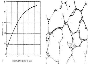
Figure
1. The effect of the addition of tin to Figure 2.
Structure of 20% aluminium-tin as cast
aluminium on the seizure resistance. and
unrolled.
The Development of Glacier 20% Aluminium-tin Bearings for
Automotive Engines
The first assessment to be made of the effective load-carrying
capacity of the 20% aluminium-tin material was obtained in a test machine which
loaded the bearing dynamically under conditions of operation which were as near
ideal as could be obtained. The machine is shown in Figure 4 and the system of
loading the bearing can be seen in Figure 5. The machine is hydraulically
loaded with the test bearing carried on an eccentric journal on a very stiffly
supported shaft. There was negligible edge loading on the bearing and the
dynamic load was unidirectional. The limit of loading for fatigue at 5 x 10⁶
cycles for the 20% aluminium-tin was 6,400 psi (44,128 kPa). Comparative results
obtained in this machine for other bearing materials are shown in Table 3.
These tests indicated that an increased usable load capacity was
being obtained and that the pattern and appearance of the fatigue damage did
not suggest that the mode of failure would be different with this material from
those in common use.
Following this, another series of tests were carried out on another
fatigue test machine, shown in Figure 6 and in detail in Figure 7. In this
machine the load was applied to the bearings by a fairly flexible shaft which
rotated at 4,000 rpm and carried two eccentric masses. The masses could be adjusted
in weight and were capable of applying specific loads up to 10,000 psi (68,950
kPa) to each of the four test bearings which supported the shaft. This machine,
with its rotating loads and flexible shafts, applied a load to the test
bearings which was more typical of that existing in an automotive engine and
therefore the fatigue strengths of typical bearing materials was lower than in
the other machine. In this case, the effective fatigue strength of the 20%
aluminium-tin material was 4,500 psi (31,027 kPa). The comparative fatigues are
shown in Table 4.
It should be noted that the effective fatigue result for 70-30
copper-lead on steel in Table 4 is not consistent with that in Table 3. This is
because of the shaft deflection and the rotating load in the second machine.
The fatigue of the unplated copper-lead was aggravated by the occurrence of
incipient seizure of the material.
These results indicated that in terms of dynamic load capacity, the
20% aluminium-tin was equal to any of the other materials which had the overall
combination of properties which made them suitable for use in internal
combustion engines. It should be noted that in Tables 3 and 4, no strength
comparisons are made with other materials which, although stronger, would have
unacceptable wear or corrosion properties. The next property of the material to
be examined was corrosion resistance and a lengthy series of tests was carried
out with the 20% aluminium-tin bearings immersed in acidic and alkaline oils
and additives. This work was done by Glacier and several oil companies,
particular attention being paid to the effects of alkaline attack. This was
because of the known effect of alkalis on aluminium itself, but no damage was
sustained in any test.
One of the most important properties of a bearing material is its
wear performance exemplified by the wear of the material itself and also by the
wear of the associated shaft material. To a large extent, the important wear figure
in a bearing is the total change in clearance since this determines whether the
engine must be dismantled for bearing overhaul and, to some extent, whether the
crankshaft must be reground. Glacier 20% reticular aluminium-tin had been
designed to run against unhardened shafts (down to 200 Brinell) and long-term
tests were set afoot in the Company's and customers' motor vehicles to assess
wear performance with soft shafts. In recent years, the distance run by
vehicles between overhauls has increased considerably, and this means that very
large distances must be run to assess the material. The copper-lead bearing
materials which run with hardened shafts have excellent wear properties as long
as the lead-tin or lead-indium overlay is not worn off. Once it has been worn
through, after say 75,000 miles (120,698 kilometres), the shaft wear rate
against the hard copper-lead or lead-bronze is extremely rapid. Typical
comparative wear rates are shown in Figure 8. Initially the wear rate with both
materials is small, although slightly more rapid with the aluminium-tin material,
until at, say 60,000 miles (96,558 kilometres), the overlay is worn off and the
copper-lead wear rate increases. If the engine is dirty or filtration
neglected, the increase of the wear rate of plated copper-lead will occur
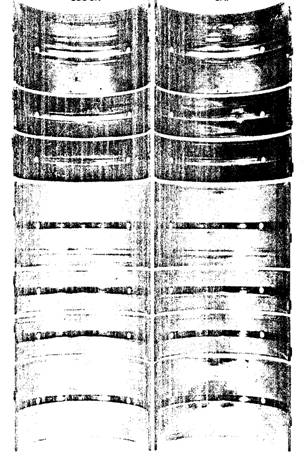
earlier in the life of the bearing. Figure 9 shows a typical set of main
bearings where the wear rate of the plated copper-lead bearings has become
accelerated. The overlay has been removed in certain areas and the hard
copper-lead exposed. It was also found that if engines containing aluminium-tin
bearings were inspected after short periods of running, early in their life,
they appeared to be wearing more quickly than plated copper-lead. It was
quickly found that this was a visual effect due to the absence of an overlay
and could be ignored.
The final formal wear test of the material was a 60,000 mile (96,558
kilometre) run at 60 mph (96.6 kph) with 1,000 cold starts of six 1,000 cc
British cars, three fitted with Glacier 20% reticular aluminium-tin bearings
and three with a competitor's overlay plated lead-bronze bearings. In each
case, the total change in bearing clearance in the vehicles fitted with Glacier
bearings was less than in the others. The results are summarised in Table 5.
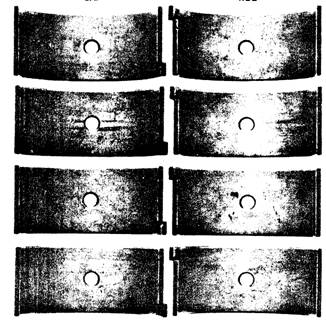
A set of 20% aluminium-tin bearings after completing the test shown
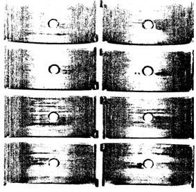
in Figure 10. In order to demonstrate that the material could survive not only
under somewhat sheltered test conditions, a 10,000 mile (16,093 kilometre) test
under racing conditions, including participation in actual races, was carried
out in a BMC Cooper car. The condition of the bearings, which is excellent, is
shown in Figure 11.
Since this development stage, considerable service experience has
been gained, where the reticular aluminium-tin bearings operated under severe
conditions for long periods. An interesting published example of this is an
article in the British "Engine Design and Application" for September
1965 where Perkins Engines Ltd. describe the successful performance of one of
their 6.354 engines in 320,000 miles (514976 kilometres) uninterrupted service.
In this case, in common with other engine components, the reticular
aluminium-tin bearings were in excellent condition and fit for further service
after engine overhaul.
A very useful additional benefit from the reticular aluminium-tin
structure – and one of particular use to the engine reconditioning industry is
that the bearings are resizable. Prefinished white metal and plated copper-lead
cannot be resized for obvious reasons but the homogeneous structure of
reticular aluminium-tin enables engine reconditioner to resize these bearings
to suit a particular shaft size should this be necessary.
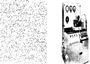
Figure 3.
Structure of 20% aluminium-tin, roll
Figure 4.
Single-head, dynamically loaded, bonded to steel, bearing fatigue test rig.
The Current Applications of Glacier 20% Aluminium-tin
Bearings
Since reticular 20% aluminium-tin was introduced by Glacier and its
Licensees some ten years ago, it has taken a prominent place in bearing
materials used in Britain and in Europe. It is used as original equipment by
BMC, Vauxhall, Ford (England and Germany) and Rootes, in their passenger cars
and trucks and is also specified by the larger British commercial vehicle manufacturers,
AEC and Leyland. A list of users of the material is given at the end of this
article. The material is also used in larger stationary and marine-propulsion
diesel engines, in diameters up to 10" (254 mm). It is also being used
almost universally as the material around which new engines are designed and developed.
This success arises from the fact that, for the first time, a bearing material
has been specifically formulated and developed for the work it has to do and
the market it has to serve. Into Glacier 20% reticular aluminium-tin bearings
are built the qualities of strength, melting point, corrosion resistance, embeddability,
conformability, hardness and surface condition in the proportions which are
required to fit exactly for the bearing requirements of the engines of today
and the future.
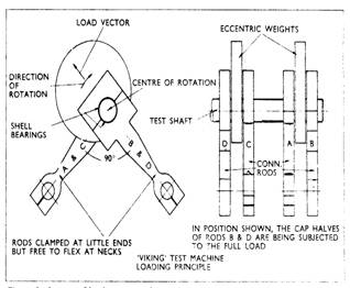
Figure 5. Layout of loading system for machine in Figure 4.
Figure 6. Multi-head, dynamically loaded, bearing fatigue test rig.
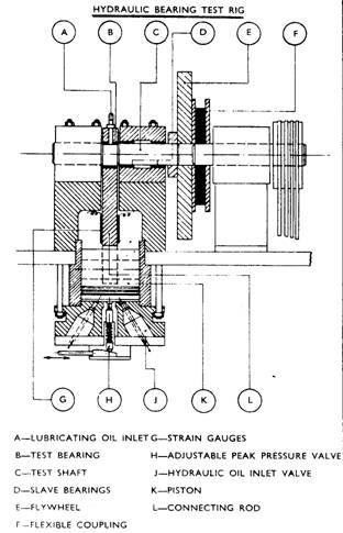
Figure 7. Arrangement of test head on machine in Figure 6.
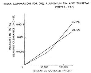
Figure 8. Comparative wear of bearing
materials
Block Cap
Figure 9. Comparative wear performance for
Glacier
20% reticular aluminium-tin material
and an overlay plated copper-lead material.
Cap
Rod
Figure 10. Glacier 20% aluminium-tin bearings after 60,000
miles
Caps Rods
Big Ends
Figure 11. Bearings from BMC Cooper engine after
10,000 racing miles.
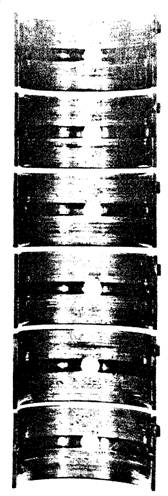
Figure 11 (Cont'd)
TABLE 1.
Typical Applications for Glacier AS15 in
Petrol Engines
|
Capacity
(litres)
|
Engine
Type
|
Bore
(ins)
|
Stroke
(ins)
|
Con Rod Bearing Load at Max Torque
(psi @ rpm)
|
Con Rod Bearing
Load at Max Speed
(psi @ rpm)
|
|
1.0
|
4 cyl
in line
|
2.458
|
3.200
|
4,100
@ 3,600
|
3,150
@ 6,000
|
|
1.5
|
4 cyl
in line
|
3.188
|
2.867
|
4,350
@ 3,600
|
3,020
@ 6,000
|
|
0.9
|
4 cyl
in line
|
2.677
|
2.377
|
4,725
@ 2,800
|
2,650
@ 6,000
|
|
0.9 uprated
|
4 cyl
in line
|
2.677
|
2.377
|
|
3,750
@ 7,500
|
|
1.7
|
4 cyl
in line
|
3.205
|
3.260
|
3,970
@ 2,600
|
4,080
@ 5,500
|
|
1.7
|
V4
|
3.920
|
2.375
|
6,096
@ 3,000
|
3,069
@ 6,000
|
|
2.0
|
V4
|
3.920
|
2.845
|
5,743
@ 3,000
|
3,473
@ 6,000
|
|
1.8
|
4 cyl
in line
|
3.160
|
3.500
|
|
5,210
@ 6,000
|
TABLE 2.
Typical Applications for Glacier AS15 in
Diesel Engines
|
Capacity
(litres)
|
Engine
Type
|
Bore
(ins)
|
Stroke
(ins)
|
Con Rod Bearing Load at Max Torque
(psi @ rpm)
|
Con Rod Bearing
Load at Max Speed
(psi @ rpm)
|
|
8.5
|
V8
|
4.250
|
4.500
|
4,450
@ 1,000
|
3,030 @ 3,250
4,980 @ 4,500
|
|
5.8
t/c
|
6 cyl
in line
|
3.875
|
5.000
|
6,314
@ 2,000
|
6,000
@ 2,800
|
|
5.4
|
6 cyl
in line
|
4.0625
|
4.250
|
4,980
@ 1,500
|
3,140
@ 3,000
|
|
5.8
s/c
|
6 cyl
in line
|
3.875
|
5.000
|
8,080
@ 1,350
|
5,500
@ 2,800
|
|
5.8
n/a
|
6 cyl
in line
|
3.875
|
5.000
|
4,115
@ 2,000
|
3,616
@ 2,800
|
t/c = Turbo charged, s/c =
super charged, n/a = naturally aspirated
TABLE 3.
'Effective Fatigue Strength' of Bearing Materials
Under Near Ideal Conditions
|
Bearing Material
|
Fatigue
Strength (psi)
|
|
Babbitt, tin
based, 0.020" (0.508 mm) thick on steel
|
2,250
|
|
Babbitt, tin
based, 0.006" (0.1524 mm) thick on steel
|
3,400
|
|
Overlay plated
copper-lead on steel
|
5,000
|
|
70-30 copper-lead
– no overlay
|
5,200
|
|
Reticular 20%
aluminium-tin on steel
|
6,400
|
TABLE 4.
'Effective Fatigue Strength' of Bearing
Materials Under Simulated Operating Conditions
|
Bearing Material
|
Fatigue
Strength (psi)
|
|
Babbitt, tin
based, 0.020" (0.508 mm) thick on steel
|
1,650
|
|
Babbitt, tin
based, 0.006" (0.1524 mm) thick on steel
|
2,250
|
|
Overlay plated
copper-lead on steel
|
4,300
|
|
70-30 copper-lead
– no overlay
|
3,800
|
|
Reticular 20%
aluminium-tin on steel
|
4,500
|
TABLE 5.
Total Change in Clearance of Bearings
after 60,000 Miles at 60 mph and 1,000 Cold Starts
|
Vehicle
|
Bearing Material
|
Mean
Change in Clearance
|
|
Vehicle
1.
|
Glacier
20% aluminium-tin
|
0.00030"
|
|
Vehicle
2.
|
Glacier
20% aluminium-tin
|
0.00040"
|
|
Vehicle
3.
|
Glacier
20% aluminium-tin
|
0.00035"
|
|
Vehicle
4.
|
Overlay
plated copper-lead
|
0.00050"
|
|
Vehicle
5.
|
Overlay
plated copper-lead
|
0.00060"
|
|
Vehicle
6.
|
Overlay
plated copper-lead
|
0.00055"
|
USAGE OF GLACIER ALUMINIUM-TIN AS15 ENGINE BEARINGS BY
BRITAIN'S MOTOR
INDUSTRY
Passenger Car
Usage
AS15 bearings are fitted in the following
current production models:
BMC Austin A40 Austin Healey Sprite Austin 1100
MG
1100 Morris 1100 Vanden
Plas 1100 Princess
Morris
Minor 1000 Austin A60 (Petrol) Austin Mini Minor
Morris
Mini Minor Austin A60 (Diesel) Morris Oxford
(Petrol)
Austin
Cooper Morris Cooper Morris Oxford (Diesel)
MG
Magnette Riley Elf Riley 4/72
Wolseley Hornet Wolseley
16/68 MG Midget
Rootes
Grp. Hillman Imp Sunbeam Rapier Singer
Chamois
Sunbeam
Alpine Hillman Minx Singer Gazelle
Singer Vogue Humber Sceptre Hillman Super Minx
Vauxhall Viva Velox Victor
101
Cresta VX
4/90 Viscount
Ford Anglia Zephyr
4 Zephyr 6
Cortina Corsair Zodiac
Truck and Tractor Usage
BMC Austin
and Morris Commercial: 1.50 litre 4 cylinder
Austin
and Morris Commercial: 2.20 litre 4 cylinder
Austin
and Morris Commercial: 2.55 litre 3 cylinder (Diesel)
Austin
and Morris Commercial: 3.40 litre 4 cylinder
Austin
and Morris Commercial: 3.80 litre 4 cylinder (Diesel)
Austin
and Morris Commercial: 5.10 litre 6 cylinder
Austin
and Morris Commercial: 5.70 litre 6 cylinder (Diesel)
Vauxhall Bedford: 214 cubic inch (Petrol)
Bedford: 220 cubic inch (Petrol)
Bedford: 200 cubic inch (Diesel)
Bedford: 330 cubic inch (Diesel)
Bedford: 60/70 Engine (Diesel)
Ford E1DDN Industrial (Diesel)
New Dorset Range (Diesel)
Dearborn Tractor Range (Diesel): Models 2000, 3000, 4000 and 5000
Perkins P
Series Engines (Diesel): Models 3.144, 3.152, 4.192, 4.203, 4.288 and 6.305
Other Diesel Range: Models 4.270, 4.300, 4.107, 4.99, 4.236 and 6.354
Leyland 370/400 (Diesel), 600/680 (Diesel)
AEC A410/A470 (Diesel), A590/A690
(Diesel)
JOWETT JAVELIN & JUPITER
CRANKSHAFT GRIND DATA
Grind data for Jowett Javelin and Jupiter model crankshaft, to suit
Reticular Aluminium-tin main and big end bearings is as follows:
With respect to Javelin Models PA, PB, PC, PD and PE, and Jupiter Models
SA and SC the main bearing and big end bearing journals can be ground to the
following under sizes – 10, 20, 30 and 40 thou. The following grind specifications
apply for the reticular aluminium-tin bearing surface use.
It should be noted that, if a white metal rear main bearing set is
used in conjunction with reticular aluminium-tin bearings at Nos. 1 & 2
main bearings, the grind tolerances shown in the Maintenance Manual apply to
the rear main journal only.
For reticular aluminium-tin bearing surface material the following
grind specification applies:
Main
Bearing Standard Size Specification 2.250” – 2.2498” (57.150 – 57.145 mm)
Big End Bearing Standard Size Specification 2.0000” –
1.9998” (50.800 – 50.795 mm)
Main Bearings: First
Grind (- 0.010”) 2.2400” – 2.2398” (56.896 – 56.891 mm)
Second
Grind (- 0.020”) 2.2300” – 2.2298” (56.642 – 56.637 mm)
Third
Grind (- 0.030”) 2.2200” – 2.2198” (56.388 – 56.383 mm)
Fourth Grind (- 0.040”) 2.2100”
– 2.2098” (56.134 – 56.129 mm)
Big End
Bearings: First Grind (- 0.010”) 1.9900” – 1.9898”
(50.546 – 50.541 mm)
Second
Grind (- 0.020”) 1.9800” – 1.9798” (50.292 – 50.287 mm)
Third
Grind (- 0.030”) 1.9700” – 1.9698” (50.038 – 50.033 mm)
Fourth Grind (- 0.040”) 1.9600”
– 1.9598” (49.784 – 49.779 mm)