TECHNICAL NOTES SERIES
JOWETT JAVELIN PA, PB, PC, PD & PE
JOWETT JUPITER SA & SC
PART V – CRANKSHAFT BEARINGS
The Jowett Car Club of Australia Incorporated is not responsible for any inaccuracies or changes that may occur within this document. Every effort has been made to ensure total accuracy. It is not a Jowett Car Club publication and, therefore the Club has no control over its contents. These Technical Notes have been compiled by using the latest information available.
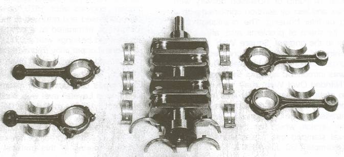
Cover photograph, with thanks to North American Jowett Register. Featured items are the internals of the R1 Jowett Jupiter.
Compiled by, Mike Allfrey – May 2004.
JOWETT JAVELIN & JUPITER CRANKSHAFT BEARINGS
NOTE: This information originally appeared in ‘Flat Four’ the newsletter of the Jowett Car Club of New Zealand of November 1978. The article has been updated by its author, Neil Moore, in 1994. Thanks are due to Neil for the work he has put into this, and for permitting this reprint.
The subject of engine bearing life has interested me ever since I became the owner of a Javelin in 1950. As my knowledge of the engine grew, it seemed the Javelin was plagued by bearing problems more or less from its beginning. The list of engineering changes show this with a number of modifications to improved bearing materials, stiffer connecting rods and crankcase, oil pump of increased delivery with larger galleries and less oil aeration combined with a non-draining oil filter housing. The crankshaft also came in for its share of problems and, after some modifications to the original ‘Square Web’ including flame hardening of journals and increased radii in bearing journal corners, the Laystall ‘Oval Web’ crankshaft was introduced at about the beginning of 1954. The ‘Nitrided Oval Web’ shaft with increased resistance to metal fatigue and wear was introduced from 1958 on. This style shaft must not be confused with the Australian Meade cast iron shaft which looks similar to the Laystall, which has the Laystall name within an oval stamped into a web surface, along with a date (example 7 60 ‘July 1960’). This gave a fairly satisfactory life of 50,000 to 80,000 miles (80,465 to 128,744 kilometres) between major overhauls if copper/lead bearings were used with the Laystall oval web shaft, and Jowetts gained a fair reputation among the motoring public for speed rather than longevity.
However, in New Zealand it seems we had another problem with inferior bearings. These gave rise to shorter life engines and some unwarranted reputations. This was due to Model CC Bradford and Javelin big end dimensions being the same, but the Bradford engine’s specification calling for white metal bearings, and the Javelin/Jupiter engine’s specification calling for copper/lead bearings. However, for approximately ten years, New Zealand produced bearings were of one type – white metal for both and the problem was further compounded by the manufacturer producing white metal shells for the Javelin front and centre main bearing sets. (The rear main bearing is white metal with thrusts anyway as this is the only way it can be manufactured.)
It must be borne in mind that this is ancient history – 1950s to 1960s – and while the local manufacturer was mistaken in producing them anyway, it was a situation created by very harsh import controls imposed by the New Zealand governments of the period. Allied to this was the fact that Jowetts were no longer being produced any more and the only people who were aware that white metal bearings were inferior in Javelins and Jupiters were the Jowett agents around New Zealand, who were kept informed of developments by Jowett Cars Limited (later Jowett Engineering), England, up to 1966 when the firm finally closed down. Boxes of these white metal bearings would be placed at the back of the shelves and have unfortunately in recent years come to light again with a lot of ex-Jowett agents quitting their little piles of parts left after all this time. All the copper/lead bearings have been used and, the white metal bearings are all that is left and now (1978) unsuspecting Jowett owners of this decade snap them up as ‘genuine’ parts – “Caveat Emptor” – let the buyer beware!
The inherent problem with these alloys were that they were prone to corrosion from the organic acids produced during combustion of the fuel in the engine which find their way into the engine’s lubricating oil. Such corrosion is increased by a breather valve as fitted to the Javelin/Jupiter engine and to most other modern engines after 1970, as crankcase gasses are condensed and returned to the engine. The corrosion was eliminated at a cost by over-plating the copper/lead bearings with a 0.001” (0.0254 m) layer of lead/tin/copper alloy to provide a high load bearing copper/lead alloy with a soft bearing surface.
A harder crankshaft surface was recommended with these types of bearings to minimise wear. (Hence the nitrided Laystall oval web shaft.) The load carrying capacity of this material is 1½ to 2 times greater than babbitt or white metal bearings, although the cost is greater due to a more difficult manufacturing process. It was not practical however to manufacture a thrust bearing of this material, so Jowetts (and several other vehicle makers) ended up with a white metal rear main c/w thrust and copper/lead overlay bearing for centre and front main bearings, though it will be noted that the rear main bearing is a little wider than the two other main bearings which partly compensates for its lower load carrying capability. This then was the state of things about the end of 1954 when Jowett Cars Limited ceased production. Since then another improved bearing material has been developed. This is an aluminium-tin alloy of approximately 80% aluminium and 20% tin, and has the same or slightly superior load carrying capacity to copper/lead and, as a bonus, is corrosion resistant and can be used with a soft shaft. It is also cheaper to produce than the copper/lead bearing surface material. This is now the standard bearing material used by ACL in making nearly all replacement bearings for the New Zealand market. These bearings are designated by a number followed by ‘AL’.
Bearing materials are only part of the story because although they play a very significant part in engine longevity, the crankshaft and its oil way design is another significant factor. Jowett were obviously worried by their numerous crankshaft breakages and the eventual oval web design overcame this defect; however, it did not solve the bearing failures. Bearing life was increased by reducing the clearances in the Series III to something like ¾ of a thousandth of an inch (0.00075”) but this, while it kept bearing leakage to a low level until wear increased the clearance, it did not get at the cause of the problem. Research on crankshaft design since 1954 has shown that the engineers at Jowett Cars Limited were “backing the wrong horse” by feeding the oil to the big ends at the trailing side of the bearing. Centrifugal force was the culprit. It is reasonable to assume that the faster a crankshaft turns (spins), the more force is exerted on the oil at the extremities of the crank and any excess clearance there could give quite a leakage. If this exceeds the feed of oil to the main bearings, they will suffer oil starvation and wear. On the Javelin/Jupiter engine the centre main bearing feeds two big end bearings, so there is twice the draw-off, while the front and rear mains only feed one big end each. In the Javelin/Jupiter Series III engine a groove was machined behind the bearing shell (slipper) in the crankcase around the housing to give continuous oil feed and, as well, a huge groove was machined around the shell on the bearing face – which was in fact one third of the surface area of the bearing. Thus we had a situation of oil being flung to the big end cranks by centrifugal force and a huge drain was supplied to help it get away!! Some relevant theory on this problem and the ways of combating it follow, per courtesy of ‘Engine Design’ by JG Giles.
“Quantity of oil required (for each bearing) will be determined by the leakage area of the bearing which is related to the diameter, length and clearance. Oil passages must be large enough to restrict the oil velocity to around 10–15 feet per second, and where one passage feeds two bearings, that is, main and connecting rod, it should be larger than one feeding the main bearing only.
“Oil is fed to the connecting rod bearing by a duct or drilling in the main bearing and/or bearing housing and oil pressure must be sufficient to overcome centrifugal effects due to crankshaft rotation on the oil in the cross-drilling in a main bearing. This centrifugal effect opposes entry of oil into the cross-drilling on one side of the main bearing and assists outlet into the connecting rod on the other, tending to create low pressure. Pressure therefore must be sufficient to overcome the centrifugal force and also maintain the rate of flow at which the oil is being thrown out at the connecting rod bearing.
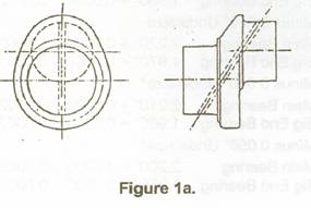
“Centrifugal oil pressure can be minimised by consideration to the position of cross drilling. Figure 1, illustrates three methods of cross drilling. Drawing at, Figure 1a and Figure 2 (upper), shows drilling on a line joining the main to connecting rod journals and maximum centrifugal forces will be evident on main and connecting rod journal diameters.
“The centrifugal pressures can have an important influence on the flow of lubricant to the various crankshaft bearings and may lead to actual starvation at high speeds when there is some wear in the bearings. Consequently the small reduction achieved by the angled drilling, Figure 1b, can produce a useful gain in this respect.
“It will be noted from Figure 2 (lower), that the effective radius on the connecting rod side and hence centrifugal pressure, has been reduced. A further reduction of course is achieved by the cross-drilling shown in Figure 1c, although this operation adds a further drilling operation to the manufacturing process and thus incurs a small cost penalty.
“This has extra advantages of:
1. Oil feed to journal at two positions;
2. Oil holes positioned where minimum load occurs;
3. Inertia force on oil is not increased by an increase in connecting rod journal diameter; and
4. Oil flow is not biased towards one side of bearing as is evident in methods ‘a’ and ‘b’.”
The reader will digest all this and say, well this is very nice – but what can I do to incorporate all this theory into my rebuilt, in 1994, Javelin/Jupiter? The answer with respect to the crankshaft theory is, very little, but maybe we can do something to the bearings. To get an idea of what has been achieved we need to look at racing engines and the other similar engine to the Jowett, the Volkswagen. Firstly, it is standard practice in Lotus Cortinas and other similar engines to replace the main bearing shells with a full oil groove all round, with a pair, one of which is plain and the other with a groove. This reduces the supply of oil to the big ends to half the crank’s revolution and retains it in the mains which seemingly is adequate! Racing ‘Minis’, sometimes reaching 9000 rpm, according to Mr Ted Thompson (balance expert from Kumea), sometimes have bronze plugs with smaller cross holes in them fitted to the cross drillings of the cranks which feed the big ends, again the purpose of which is to restrict the oil flow to the big ends which is adequate at high revs due to centrifugal force anyway. And, of course, the Volkswagen engine which is very similar to the Javelin/Jupiter engine was, in the early 60s, having the same troubles with centre main bearings wearing out for exactly the same reasons, albeit ten years later because of the unstressed nature of the Volkswagen engine. Their solution was to fit a completely plain bearing shell in both halves (the front and rear were made in one piece and pressed into the crankcase) for the centre and plain front and rear except at holes and the shaft journal had a small groove ground into it for about half an inch around the circumference area in line with the hole, giving a squirt of oil each time the groove passed the holes.
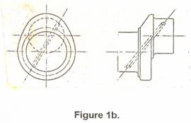
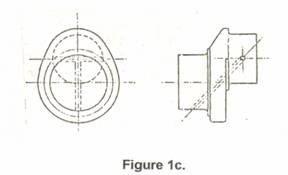
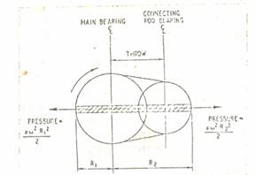
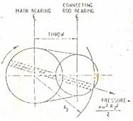
Figure 2.
MAIN BEARINGS
So, here we have some solutions to the centrifugal problem, but which is the easiest (and cheapest) way of applying this to the Javelin/Jupiter? Well, as the crankshaft is nitrided (case-hardened and hard, it is probably best to leave well alone; the plug idea did not appeal due to balancing problems. This left the main bearings, which as the originals had a much-reduced surface area due to the one-third groove, to be improved. A search of the bearing manual shows that the Perkins three-cylinder diesel engine as fitted to the K135 Massey-Ferguson tractor (and numerous other vehicles) had a big end shell of the same dimensions as the Jowett main. How convenient! A three cylinder too, providing a boxed set of three pairs of shells – in aluminium too! So, we machine the shells. Not as with the Lotus engine, because it is an in-line engine, so we put a small groove from the oil hole to the join, which in the Javelin/Jupiter is vertical. This is ideal because in a horizontally opposed engine the load is at the centre of the shell. With an in-line engine, the load is on the bottom so a plain shell can be fitted to the bottom half and a grooved one to the top half of the main bearing. We can go one better by installing three sets of shell bearings throughout the mains and fitting some thrust washers to the rear faces of the rear bearing. Again, consulting the bearing catalogue, we find that almost all standard thrust washers are 0.093” thick. This means that the crankcase will have to be machined to allow the thicker washers to be installed. So much for theory, let’s put it into practice.
Firstly, the crankshaft, find one that will stand grinding to the next undersize and take it to an engine reconditioner who understands Volkswagen crankshaft grinding requirements. Ask around, as the Volkswagen shaft is nitrided, of similar shape to the Jowett shaft and requires the same 0.100” radius at the journal corners. Most engine reconditioners who do these shafts regularly will have a special wheel which they install on their grinding machines, for which they may charge a little extra. If in any doubt, contact someone who knows, or contact the Volkswagen Club. In the Melbourne area, have the shaft ground at Orger Engines, 10 Scoresby Road, Bayswater – our contact there is Lindsay Dyer.
Those connecting rods with sharp corners at the big end bearing bore, must have a suitable chamfer machined at this edge. Otherwise the connecting rod will pinch at the crankshaft big end bearing journal radii, when the big end bolts are tightened. The chamfer should have a 0.125” face at 45° cut angle.
Have the shaft ground to one of the following sizes, depending on the condition of the shaft you have.
Crankshaft Grind Data
Standard Size
Main Bearing 2.250” + 0.0000, - 0.0002”
Big End Bearing 2.000” + 0.0000, - 0.0002”
Minus 0.010” Undersize
Main Bearing 2.240” + 0.0000, - 0.0002”
Big End Bearing 1.990” + 0.0000, - 0.0002”
Minus 0.020” Undersize
Main Bearing 2.230” + 0.0000, - 0.0002”
Big End Bearing 1.980” + 0.0000, - 0.0002”
Minus 0.030” Undersize
Main Bearing 2.220” + 0.0000, - 0.0002”
Big End Bearing 1.970” + 0.0000, - 0.0002”
Minus 0.040” Undersize*
Main Bearing 2.210” + 0.0000, - 0.0002”
Big End Bearing 1.960” + 0.0000, - 0.0002”
Minus 0.050” Undersize*
Main Bearing 2.200” + 0.0000, - 0.0002”
Big End Bearing 1.950” + 0.0000, - 0.0002”
Minus 0.060” Undersize*
Main Bearing 2.190” + 0.0000, - 0.0002”
Big End Bearing 1.940” + 0.0000, - 0.0002”
* Ensure that bearing sets of undersizes 0.040”, 0.050” and 0.060” can be obtained before commencing the crankshaft grinding operation. These bearing sets are usually available from Jowett Club Spares, ex-stock.
Should you purchase your main bearing set from your Perkins Engines dealer, or from a Massey-Ferguson dealer, ask for big end shells for either P3-144 (2.36 litres) or P3-152 (2.5 litres), or, Massey-Ferguson 3A-152 engine for MF-35, 35X and135 Tractors (agricultural), their part number 85035. Incidentally, these bearings may carry the ACL marking ‘3B1012AL’, (Perkins Power Part Number 85036-B, Glacier GS8955 in England) on them as they are manufactured in Australia by ACL and packed for their respective suppliers. Also, it is worth mentioning here that these bearings are a plain shell for the big ends of a three cylinder diesel engine. Perkins also happen to make four and six cylinder engines with the same physical dimensions. The three cylinder set is best because it ideally suits our purpose by providing the right number for the Javelin/Jupiter mains. These bearings must be modified to fit into the Javelin/Jupiter crankcase, Pages 6, using the following procedure:
Step One
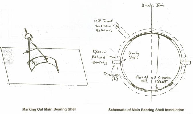
Carefully file the tangs off the bearing slippers, so that the outer edge of the shell is flush and will not distort as the crankcase is assembled. Some may ask, why not use the tangs? But, if the way the Javelin/Jupiter crankcase was machined is considered, an explanation will result. The two halves were bolted together and the crankcase was bored for main bearing and camshaft bores as one piece. Thus the centreline of the crankcase may not coincide with the centre of the bearing bores. Therefore if one half circle is smaller than the other, the shell would not fit. So by placing a dowel at right angles to the join the bearings will fit and still stop being spun in the block.
Step Two
Mark out the three holes per shell as follows – take a pair of dividers and, placing the shell on a flat surface, scribe a half line from each join side to find the centre of the outside. Then, taking an old Jowett supplied shell, mark from it the two oil supply holes in roughly the same position. Then equidistant from each edge mark the three holes on the centreline.
Step Three
Centre pop and drill them – the dowel hole having a clearance of 3/16” (a Number 11 drill can be used) and the oil supply holes being ¼”. De-burr the holes after the drilling operation.
Step Four
This part is the crux of the bearing – machining the groove – and will depend on the model of the block you are to use for your engine. Bearing in mind the preamble about oil flow and centrifugal force and so on, I have concluded that the easiest method of obtaining the desired effect from the various alternatives, is to modify the bearings. Now if the crankcase is an early PA, PB, PC or SA, it will have no oil groove machined behind where the bearing shell fits. If it is a later PC or SA model, it will have the centre main housing grooved only. If it is a PD, PE or SC crankcase it will have all three main bearing bores machined with a groove. All early engines reconditioned by Jowett Engineering were modified in this manner. All PA, PB and early PC and SA – a thin groove will need to be machined around all bearing bores approximately 0.040” deep and no more than 0.125” wide. The later PC and SA – the front and rear main bearing bores will require machining as above, but the centre main will be machined differently as follows (remember it feeds two big ends). Taking the later PC, SA, PD and PE – again about 0.040” deep and 0.25” wide machine a groove from the oil holes to the join line of the bearing. This can be done with a rotary file bit and an electric drill, or machined on a lathe or milling machine. When the two bearing halves are held together the grooves will join oil hole to oil hole across the top and bottom (low load area) of the bearing.
Step Five
Bevel the edges of the shells at 45° as they are a fraction wider than the original shell and may foul the large radius on the corners of the shaft journals – front and centre only.
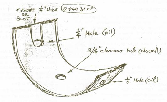
Dimensions for Grooving Perkins Bearing
Step Six
Check the shells for any burrs caused by drilling or machining and remove same, thoroughly clean the shell set and install. Note – the dowel holes could want slotting with a round file a little on one side to ensure no binding.
It will be obvious, of course, that the PD, late SA, PE and SC crankcase sets with grooves behind each main bearing will give the best results, and the earlier crankcase sets will only be a compromise. However, if the engine re-builder desires a PE result from a PA, PB or SA crankcase, the answer is to machine the block with a groove at all three bearing housings. This can be done without removing the dowels by machining a groove slightly to one side of the dowel and making a shallow dent with a die grinder or burr in a drill to mate up with the oil holes or, the dowels can be removed by forcing grease, through the hole provided, equipped with a needle point nozzle. The crankcase halves can then be set up and machined as per the PE and SC crankcase, using a 5/8” diameter spot facing drill (end mill).
SEPARATE THRUST BEARINGS
The next stage is the fitting of the rear thrust washers. First purchase thrusts for, ACL part number 2T2167 (Ford Cortina Mk 3), or Repco part number 2T3188 (Ford Zephyr Mk 1 – Glacier W2058). Four individual half washers per engine are required. These washers are 0.093” thick, the original Javelin/Jupiter thrust flanges on the rear main bearing are 0.073” thick. This means that 0.020” will have to be machined off the crankcase set at front and rear of the rear main bearing faces. Reducing the thickness of the separate thrust washers is an option, but it should not be used because, for future overhauls, non standard parts will be required – thus making the job somewhat difficult and very time consuming. It is much better to machine the crankcase set and be done with it – in future, thrust replacement will be that much simpler.
A special tool can be made-up for machining the rear main bearing front and rear faces by hand. For details see sketch on Page 9. The items that need purchasing are:
2 Sealed bearings, SKF RLS8 or equivalent Hoffman LS10.
2 Pairs of old standard size front and centre main bearing shells.
3 Cap screws 5/16” x ¾” (Whitworth or SAE).
1 Thread tap set to suit cap screws.
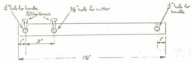
1 Length of 1” diameter bright mild steel bar 19” long. Ends de-burred.
1 Length ½” diameter bright mild steel bar 18” long.
1 Piece of 3/8” diameter tool steel, HSS.
1 Mild steel collar with 1” bore and with cap screw.
1 Front hub distance tube, Jowett part number 50383 to use as a spacer.
1 Set of feeler gauges.
The following procedure should be used to make-up the machining tool:
1. The piece of tool steel is sharpened for about 1” of its length by being ground flat to the half-way line, taking care not to overheat while grinding. A light hone with an oil stone will give a good cutting edge on either side.
2. The 1” diameter bar is drilled as shown in the drawing on Page 9.
3. The ½” diameter bar is bent to form a handle with a 6" grip area.
4. The standard size bearing shells should be installed in the crankcase set, at front and rear main bearing supports, with a with a piece of Cellotape, wrapping the RLS8 bearings, with one layer to take up clearance. The front bearing has to be held firmly in place as this will control depth of cut.
5. The ball bearings will sit in the shells and the two crankcase halves are then bolted together with four tie bolts – two at front and two at rear – to hold the ball bearings in a nipped condition. Make sure that the two joint faces are thoroughly cleaned before joining.
6. The boring bar will then slide through the ball bearings.
7. The cutter blade is fixed by a cap screw in the boring bar at right angles to the face to be cut.
8. The front hub distance tube and collar are slid on to the boring bar against the rear bearing’s centre race, at the outside end, and with the handle inserted at the opposite end to the cutter blade.
9. The collar is set with the cutter blade pressed against the crankcase, and a suggested 0.020” feeler gauge is placed between the collar and the spacer. The collar is set and locked on to the boring bar with a cap screw. The cutting depth is now set. Cutting material from the rear face can commence by turning the handle, while maintaining a moderate pressure on the boring bar until the collar sits on the bearing spacer and the 0.020” thickness of material has been cut off. The aluminium cuts quite easily and smoothly with only moderate pressure applied.
10. The process is then reversed by placing the cutter blade on the front face of the rear main bearing web, changing the handle to the other end and setting the collar gap again. It should be noted that on the inner face of most crankcases there is a partly machined step where the original flanged bearing was located. The higher portion requires to be carefully cut down to the original bearing flange level and then the 0.020” removed from the face.
Note: The rear main bearing supports require machining at front and rear faces to provide 0.002"-0.004" crankshaft end float. Equal amounts must be cut from both faces of the support.
Next is the job of drilling and tapping the crankcase set for the thrust washers:
1. Mark the steel face of one of the thrust washers 15/16” (24 mm) from the crankcase centre line edge, and centre the screw hole in the washer half. The 15/16” dimension ensures that the oil gallery is avoided.
2. Using a pedestal drilling machine (it is essential that the holes are square and straight), with a 2.5 mm drill, the correct tapping size for 3 mm thread, centre-drill the two holes and then drill right through the thrust washer.
3. Use the drilled washer as a template to mark the crankcase, each half, and again using a pedestal drilling machine, drill right through the rear main bearing support from the rear. Use a suitable cutting fluid or the drill will grab, as will the 3 mm tap later, and clear the drill frequently.
4. Tap the holes, with a 3 mm x 0.5 mm pitch tap, to halfway point, from each face, to allow enough thread for the screws, clear the swarf frequently. It is essential that a threading lubricant, suitable for use in aluminium, is used while cutting the threads. A broken tap could certainly result if a lubricant is not used. The best lubricant is Tapmatic Dual Action ‘Plus 2’ or, copious amounts of clean kerosene can be used.
5. Lightly clamp the thrust washers in their correct position and, using the 2.5 mm drill, mark the backs of the three remaining un-drilled washers. Accurately mark with centre punch and drill the all washers with 3 mm drill. Countersink on the bearing surface side so that, when the screws are tightened, their heads are just below the white metal (or bronze) on the washer face.
It may be necessary to slightly countersink the threaded holes in the crankcase, so that the screw heads clamp the thrust washers firmly against the rear main bearing support faces.
Note – Mark individual thrust washers with a dot punch to identify their positions on the crankcase, the hole centres may vary slightly, due to the drilling of the bearing support.
6. Install the thrust washers, using 3 mm x 12mm countersunk screws, and check that the crankshaft has the correct end-float using a feeler gauge. A small drop of Loctite ‘Nutloc’ under the head of each screw will keep them secure. Do not apply Nutloc to the thread, otherwise it will not be possible to remove the screws when replacing the thrust washers.
BIG END BEARINGS
For the Javelin, Jupiter (and CC model Bradford) big end shells. There are two alternatives. The ACL 2411AL (Glacier GS 8899SA in England) shell is available from Perkins dealers, as a big end shell for the 4-cylinder 1.62 litre Perkins 4-99 diesel engine. The width of these bearings is 0.875” and 0.075” should be machined from the tang side to stop the edges fouling on the big end journal radius of the crankshaft.
Note: The locating tangs may need to be filed narrower if the connecting rods have narrow tang grooves.
The second alternative that can be used is the ACL, part number 4B2641AL, from the Hillman Avenger 1970 on, available from most suppliers. These bearings are the correct width..
The bore diameter in the Javelin/Jupiter (Bradford CC) connecting rod for the big end bearing shells is 2.1445” – 2.1450”. The bore diameter in the Hillman connecting rod for the big end bearing shells is 2.1460” – 2.1465”. Since no original Jowett big end bearing shells are currently available, it is advisable to have the connecting rod big end bores checked for roundness and correct size. They can be honed to 2.1460” prior to installing new bearing shells.
Those connecting rods with sharp corners at the big end bearing bore, must have a suitable chamfer machined at this edge. Otherwise the rod will nip at the crankshaft big end bearing journal radii. The chamfer should have a 0.125” face at 45° cut angle.
The tangs may also need to be filed to suit the connecting rod tang grooves, so that the bearing can be located in the centre of the connecting rod bore.
IMPORTANT NOTE
It should be noted that there may be some instances where the crankshaft may have been ground oversize between the thrust faces at the rear main journal. If this is the case, then less material than the stated 0.020” will have to be removed. Consideration will have to be given to aligning the crankpins with the centreline of the cylinder bores. A rough indication of correct crankshaft axial position is when the front journal is flush with the front face of the front main bearing support.
CONCLUSION
The Jowett Car Club of Australia Inc keeps stocks of main and big end bearings sourced from New Zealand. They also keep in stock a quantity of thrust washer sets for installation in crankcase sets. The advantage of employing separate thrusts is that the same specification main bearing sets can be used throughout the engine.
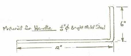
Dimensions for Tool Rotating Handle
Material for Bar 1" Diameter Bright Mild Steel
COMPONENTS FOR CRANKCASE MACHINING TOOL