Introduction
Note:
Items marked with an asterisk * signify parts which need not be removed
and can be left on the engine until it is out of the car. Here it is assumed
that a total reconditioning of the engine is to take place and these parts will
have to be removed anyway. To anyone unfamiliar with removing the engine it is,
in the opinion of the writer, advantageous to strip a good deal of the engine
in situ to make it easier to handle. On the other hand some find the parts more
accessible and easier to dismantle after the unit is out of the car.
Item 20 -
Preparation
20.0. The
car should be parked on a level concrete floor, jacked up and mounted on four
secure chassis stands so that access to the gearbox can be gained.
20.1. Unscrew
the oil filter drain setscrew (on the RHS of the rear timing cover)
about 3/4" but do not remove it.
20.2. Drain
coolant and oil from engine and gearbox.
20.3. Disconnect
battery cables.
Item 22 – Removing Body
Parts
22.0. Single-piece
grille.
22.1. Raise
bonnet and fully back off the two upper knurled brass nuts.
22.2. Unlatch
lower catches and lift the grille assembly away.
22.3. Two-piece
grille.
22.4. Raise
bonnet and fully back off the two upper knurled brass nuts.
22.5. Lift
the upper grille portion away.
22.6. With
a large screwdriver, release the four quick-release fasteners, located at each
corner between the slats, in the lower grille and lift it away.
22.7. Remove
¼" BSF setscrews holding apron (1836) noting exact position of spacers and
grille fasteners for two-piece grille.
22.8. Taking
care of rubber mouldings between apron and body, remove apron. (Rubber
mouldings are attached to apron.)
22.9. Remove
front bumper and engine sump protection bar together. Two large setscrews
hold the bumper springs to the cast iron brackets protruding through skirt of
front wings. Four bolts, two each along side of sump secure sump protection
bar. Remove these and withdraw assembly complete with bumper.
Item 24 – Removing Ancillary
Equipment
24.0. Mark
plug leads from distributor with suitable self adhesive tags.
Do
not cut notches in the insulation. Use the following notations:
‘1’
Near-side front; ‘2’ Off-side front; ‘3’ Near-side rear; ‘4’ Off-side rear
‘Coil’
to HT coil socket. Remove distributor cap and disconnect low-tension cable.
24.1. Remove
the advance-retard vacuum pipe from RHS carburettor. The union nut at
distributor end is 3/8” AF SAE. Use two spanners, at the carburettor end, since
using a single spanner will probably cause the union nipple to be detached from
pipe.
24.2. Remove
the distributor clamp bracket and note spacer under bracket. Lift the
distributor clear of engine.
24.3. Disconnect
flexible petrol pipe at upper end.
24.4. Disconnect
petrol pump from delivery pipe to carburettors.
24.5. Carefully
identify securing screws and remove them from the petrol pump flange and withdraw
pump.
24.6. Withdraw
the petrol pump operating rod (1506), place in plastic bag and keep safe.
24.7. Remove
petrol delivery pipe (1495)* connecting carburettors by unscrewing
banjos on carburettors. These banjo bolts have fine mesh filter gauzes and they
are a different thread size from the very similar bolts in the petrol pump.
24.8. Unscrew
and remove choke wires from carburettors.
24.9. Slacken
nut holding end of accelerator cable to throttle rod (1585) connecting carburettors.
24.10. Pull
cable and its outer through its bracket on the RHS tappet chest cover. Fasten
clear of engine.
Note:
In order to fasten out of harm various parts of the car the type of rubber
cables used for holding luggage in place are very convenient. If parts are
simply left loose they will become trapped and damaged when the engine is
withdrawn and replaced.
24.11. Slacken
jubilee clips securing air intake bellows to carburettors. Disconnect bellows.
24.12. Remove
nuts (two for each carburettor) securing carburettors (1595 and 1596)*
to cylinder heads. On RHS carburettor loosen link wire between choke and
throttle arm. Move fast idle link wire to highest position to make access to
nut easier.
24.13. Lift
off carburettors.*
24.14. Disconnect
oil pressure gauge or, on some models the cable to the oil pressure switch on
the LHS of the oil filter housing. Fasten clear.
24.15. Uncouple
electrical cables to dynamo. Fasten clear.
Item 26 – Removal Of Water
Pump, Fan, Exhaust System And Coolant Hoses
26.0. Remove
top hose (437) from water pump to. radiator.
26.1. Remove
heater hose from water pump (374) body on LHS. Fasten clear.
26.2. Loosen
jubilee clips on hose (436) below pump attaching it to front timing cover.
26.3. Identify
setscrews fastening water pump bracket to dynamo and front timing cover. Remove.
26.4. Remove
fan belt (376).
26.5. Remove
Simmons nuts holding fan shaft supports (402) to crankcase. Note double coil
spring washers which must be replaced.
26.6. The
water pump/fan assembly can now be removed. (This may require some juggling,
but it is quite possible!)
26.7. Remove
front wheels (1720).
26.8. Uncouple
exhaust at rear of LHS manifold (86). Nuts may be stainless steel or brass and
if so should be noted.
26.9. Remove
both manifolds complete with front pipe.*
NOTE:
If you do not remove the front pipe (1640) do not be tempted at any stage to
use it as a handle to move the engine! The manifolds will almost certainly
break.
26.10. Slacken
jubilee clips holding water hoses (438) at bottom of radiator to rear of
crankcase. These clips may be accessible beneath wheel arches or else by a long
screwdriver from inside the engine compartment.
Item 28 – Removal Of
Cylinder Heads*
Items
28.0. to 28.12. are optional at this stage.
28.0. Working
under the front wings remove the rocker covers (91) from each side of the engine.
28.1. Loosen-off
the nut on the central cylinder head stud securing the oil feed banjo (229).
28.2. Remove
retaining nuts and special washers on long studs holding rocker shaft pedestals
(239) to heads. loosen both nuts a little at a time so as not to put a strain
on the rocker shafts. Identify washers.
28.3. Remove
centre stud nut, plain washer and fibre washers retaining the banjo (229) in
the centre of the head, withdrawing the rocker shaft assembly after doing so.
28.4. Prepare
some means of identifying (neither a hacksaw nor a file) push rods and their original
position in the engine, e.g. a piece of stiff card with numbered holes.
28.5. Remove
the push rods and store so that they can be returned to their same position on
reassembly.
28.6. Strictly
following the sequence shown in the Maintenance Manual, remove cylinder head
nuts and washers, releasing all a little at a time.
NOTE:
Nut on stud number ‘1’ has, already been removed (28.3.)
28.7. Remove
any traces of lead wire around cylinder head studs.
28.8. With
a sharp point tool, prise out centre head stud water seal (321). (Rubber ring to
be found in recess round base of number ‘4’ stud.)
28.9. Attempt
to pull off head. If necessary tap around head with wooden mallet.
28.10. If
head still does not move try to lever with a broad slim lever just behind the
top corners of head and nowhere else. Under no circumstances
must screwdrivers etc. be used to lever the head in positions where the head
gasket is situated, this action will ruin the crankcase.
28.11. Another
method of releasing the head is to re-connect the battery lead temporarily. Put
about 100 cc of engine oil into the cylinders through the plug holes. Replace
the plugs and keeping clear of the engine operate the starter. The cylinder
compression may well force the head off.
28.12. If
the gasket seal is once broken the head can usually be removed by a gradual
rocking movement. Otherwise a special puller illustrated in Technical Notes
Series Part III, may ,be needed.
Item 30 – Starter Motor
Removal
30.1. Check
that the battery leads are disconnected.
30.2. From
under the car, uncouple the heavy cable to the starter motor. Fix it clear.
30.3. The
starter is held to the clutch housing (495) at the top by a bolt and nut and at
the bottom by a stud and nut. Remove the nut and bolt, and the nut from the
stud.
30.4. Note
the position of the starter terminal, in order that the starter motor can be
returned to the same position.
30.5. The
starter can now be manipulated around the flywheel ring gear and removed.
Item 32 – Detachment Of
Gearbox
32.0. It
is possible to remove the engine from the car, and leave the gearbox in-situ
but this is not the recommended method, since there is a risk of damage to the
gearbox input shaft.
32.1. Remove
the clutch housing base cover (495).
32.2. Support
the front prop shaft (800) loosely.
32.3. Two
bolts secure the front Layrub coupling (801) to the gearbox output flange (622)
and two to the front prop shaft. The nuts are secured by split pins.
32.4. Remove
split pins and all four nuts and bolts. This will require the rotation of the
shaft, entailing a rear wheel to be raised and the car out of gear.
NOTE:
Above the front Layrub there is a domed metal plate in the floor board.
Normally this is held by permanent rivets but these can be removed and replaced
by self tapping screws. This allows access to the Layrub bolts in a way which
may be found more convenient.
32.5. The
Layrub sleeves are a tight spigot fit in the flanges and usually need to be
prised out gently with a lever.
32.6. Remove
Layrub. Do NOT let propeller shaft hang far out of its normal line.
32.7. Remove
split pin from gearbox main (third motion) shaft and nut (624)
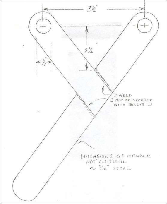
32.8. To
remove nut it will almost certainly require that car is placed in bottom gear.
If this does not hold the gearbox mainshaft, the ring gear can be held with a
hardwood wedge. The ideal tool for removing this nut is shown in the sketch in
Appendix I, which can be bolted on to the output companion flange.
32.9. It
is unlikely that the output flange will be easily removed from the shaft, but
it is worth a gentle tap with a hammer for luck! A suitable puller will be
required. The proper tool is shown in Figure 12, Page 154 of the Maintenance
Manual. However, a tool can be made up by using a spare output companion flange.
Two Layrub bolts can be used to fasten the spare companion flange to the one on
the gearbox, face to face using a substantial washer or spacer pad to bear on
the end of the main shaft.
32.10. The
method of using a puller of this kind is to tighten the two bolts dead tight
By doing this the flange may be removed, but more probably it will require a sharp
blow with a heavy hammer. Beware of the flange suddenly springing off with some
force – keep well clear!
32.11. Remove
the speedometer drive cable from RHS rear of the gear box (616), The brass
knurled nut may require a multi-grip hand wrench more often than not. Fix the
cable out of the way.
32.12 Remove
the split pin from the clutch operating rod clevis pin (520) and lift out the
pin, disconnecting the clutch operating rod (518). Tie the rod up out of the
way.
32.13. From
inside the car remove the gearbox cover (2153) from the toe board, extracting
the screws.(The screws are threaded into captive nuts).
32.14. Remove
split pin from the gear change link socket (716) at gearbox end of rod. Now unscrew
the socket adjustment screw (718) and lift off the rod.
32.15. The
selector change link (see 753) is best removed with the ball joint which is
bolted onto its lever (638) on the gearbox. Alternatively, it can be removed by
pushing back the tabs on the ends of the spring clip around the socket, but
this action is likely to damage (break) the spring clip.
32.16. Tie
the gear change and selector change links out of the way.
32.17. Through
the same opening feel the gear change stay which connects the gear change
column to the centre top of the clutch housing. (This may not be present on
cars prior to Chassis Number E1 PC 20135) Remove the nut and dished washer from
the stud on the clutch housing and lift off the stay and rubber bush. It may
help to slacken-off the bolt securing the column end of the stay assembly.
32.18. Remove
the electrical cables to the reversing light switch on the gearbox if it is
fitted.
Item 34 – Removal Of Engine
Mountings
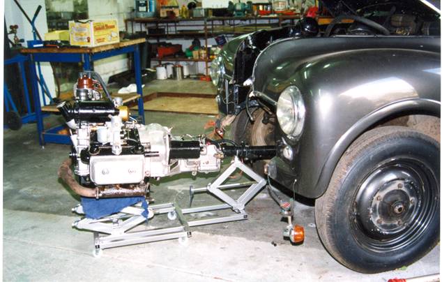
34.0 It
is quite possible to remove the engine by supporting it well and pushing the
car away from it. Some in fact prefer to do this, but the correct method is to
use some form of trolley on which the engine and gearbox unit can be wheeled
out. A suitable trolley is illustrated on the front cover. It is most important
that such a trolley has a wide enough base to carry the engine safely. If a
small lightweight trolley jack is used there is always the danger of the engine
falling off the jack.
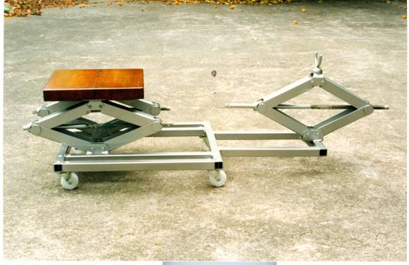
A
very adaptable trolley can be fabricated from lightweight square steel tubing,
with four castors and three scissor type car jacks. The three jacks should be
the same and can be obtained from a wrecker’s yard. See Appendix II.
NOTE:
It will be assumed from here-on that a trolley is used.
34.1. Place
a piece of clean dry towelling cloth on the trolley where the sump will be
supported, to help prevent slippage.
34.2. Just
support the engine and gearbox on the trolley. The cradle shown in "the
Maintenance Manual Page 21, Figure 20 is ideal but not essential. From that
figure it will be seen that the centre of gravity of the engine and gearbox is
about three inches in front of the flywheel, with the cylinder heads in
position.
34.3. From
underneath the car withdraw the three set screws holding the rear mounting to
the chassis cross member.
34.4. Remove
the bolts from the front engine mounting brackets (299 and 300), from the frame
side member extensions (2185 and 2186), one set screw and one nut and bolt each
side.
NOTE:
Carefully adjust the three trolley mounted jacks so that the front and rear
mounting bolts can be withdrawn without damaging their threads.
Item 36 – Removing The
Engine Assembly
36.0. The
engine and gearbox unit is now free, and can be gently edged forward.
36.1. Special
care must be taken when moving the unit, particularly that it does not fall off
the trolley. Fingers must be kept clear of places where a movement of the
engine could trap them against the body of the car. It would be quite easy to
lose a finger in this way, if the engine was to slip. Remember that it is a
very heavy and rather ungainly object.
36.2. Do
not wear loose clothing, a scarf etc. Strong protective gloves are desireab1e
and substantial boots.
36.3. Once
removed from the car make sure the unit is securely supported.
36.4. Remove
the gearbox from the engine by removing the two nuts from the top of the gearbox
and the two from inside the bell housing below.
36.5. Once
the box is free remove it. Do not leave it hanging on the clutch (first
motion) shaft when partly drawn back.
36.6. The
engine is now ready to be dismantled.
Final Note
The
engine can be removed with distributor, dynamo and starter motor attached.