PART ONE:
WORKING
PRINCIPLES
Application
The Laycock de Normanville 'Overdrive' with
Lucas Ele-ctrical Control is now being applied to an increasing number of
British Cars.
The vehicles which come to mind at once
are:
The Austin Healey – 100, The Standard
Vanguard, Triumph Roadster and Renown, Rover 90, 100 and 105, Jaguar Mark VII –
XK 140, Triumph TR2, Bristol 405, Vauxhall Velox and Wyvern, Sunbeam Alpine
Special and Mk III, Humber Hawk Mk VI, Ford Zephyr and Consul, Swallow Doretti.
For those of us who are unfamiliar with the
overdrive, we shall explain the general functioning of the equipment and its
electrical control.
The Overdrive
On The Car
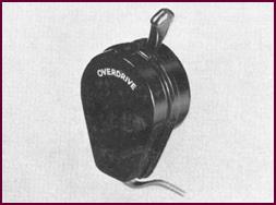
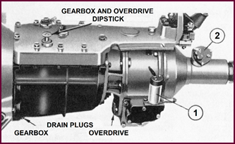 Figure 1 shows the
'overdrive' Gear Box in place behind the normal gearbox. Two of the major electrical
components are visible, the Main Operating Solenoid low down on the side '1'
and the Centrifugal Switch mounted on top at the back of the gear box at point '2'.
Figure 1 shows the
'overdrive' Gear Box in place behind the normal gearbox. Two of the major electrical
components are visible, the Main Operating Solenoid low down on the side '1'
and the Centrifugal Switch mounted on top at the back of the gear box at point '2'.
Figure 1. An overdrive unit on a gearbox
with two of the electrical components labelled.
To give some general idea as to how this
equipment works we cannot do better than briefly run over the manufacturer's
own description of it.
As will be generally realised, a motor car
engine depends partly for its power development on the number of revolutions
per minute, hence the provision of inter-mediate gears enabling the engine to
revolve at higher. revolutions for a given road speed, and so provide the ad-ditional
power required for acceleration and hill climbing.
In direct or top gear the only
multiplication of engine revolutions in terms of the driving road wheels is
through the rear axle, in which the crown wheel and pinion provide a reduction
ratio to suit the particular vehicle.
Considerations of engine power available,
the weight of the vehicle, wind resistance and other factors, determine the
actual ratios and top gear performance.
The direct top gear, whilst providing for
high cruising speeds must remain sufficiently flexible to avoid frequent gear
changes at lower road speeds.
It will be appreciated therefore, that the
selection of such an axle ratio must be something of a compromise. To provide
for flexible top gear performance at lower speeds, something must be sacrificed
at the maximum. In other words, the engine revolves faster than is actually
neces-sary at higher speed.
A means of overcoming this problem is to
over-gear, or 'overdrive' the speed of the propeller shaft, and thus the road
wheels, in relation to engine revolutions, or, vice versa, to reduce the speed
of the engine in relation to the road speed.
A very high top gear, possibly a fifth,
could be incorporated in the ordinary gearbox. With such a gear, however, it
would then be necessary to make far more frequent use of clutch, accelerator
and gear lever to engage the next lower gear in order to meet any sudden power
demand.
Road Speed
Comparisons
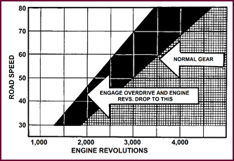 This diagram shows a typical example of engine speeds
in top gear and overdrive in relation to road speed.
This diagram shows a typical example of engine speeds
in top gear and overdrive in relation to road speed.
Figure 2. Diagram of road speed
comparisons.
The vertical ordinate of the graph shows
road speed, and the horizontal, engine revolutions. The cross hatched area
shows the comparative road speeds and engine revolutions in normal gear, and
the solid black section makes the same comparison with the car in overdrive.
Let us take one example – that of 3,000
engine revolut-ions which you will see on the bottom line. If you carry your
eye up to the inter-section of the hatched area and the black you will see that
at 3,000 engine revolutions in normal gear we have a road speed of 50 miles per
hour, with a corresponding road speed of 70 miles an hour when in overdrive at
the same engine speed.
Conversely, if we take a road speed of 50
miles an hour it will be seen that in normal gear the engine is doing something
over 2,000 revolutions for the same road speed. We should therefore, anticipate
a substantial improvement in petrol economy in overdrive.
Principle Of
Operation
Basically the 'Overdrive' consists of an
epicyclic gear train, which comprises a SUN wheel 'A', a pair of PLANET Wheels 'B'
mounted on a PLANET CARRIER 'D', and an ANNULUS or outer ring 'C' – as shown in
Figure 3.
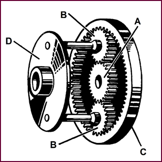 If the planet carrier is rotated whilst the sun
wheel is locked to the annulus or the planet carrier, the whole gear train will
rotate as a solid unit giving a direct through drive.
If the planet carrier is rotated whilst the sun
wheel is locked to the annulus or the planet carrier, the whole gear train will
rotate as a solid unit giving a direct through drive.
Figure 3. The epicyclic gear assembly.
If on the other hand, the sun wheel is
locked preventing it from rotating, and the planet carrier is turned, the
annulus will be overdriven at a higher speed
than the planet carrier.
How It Works –
Direct Drive
 In addition to an epicyclic gear train similar to the
one depicted in Figure 3, there is also a hydraulic pump, a hydraulic
accumulator or pressure storage chamber, a roller clutch and a sliding cone clutch.
In addition to an epicyclic gear train similar to the
one depicted in Figure 3, there is also a hydraulic pump, a hydraulic
accumulator or pressure storage chamber, a roller clutch and a sliding cone clutch.
Figure 4. Schematic of direct drive –
top gear.
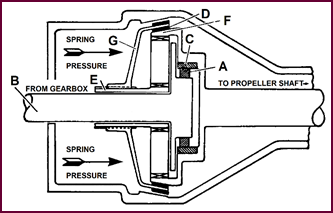
When in direct gear the overdrive is
inoperative. The drive is taken from the driving shaft 'B' through the rollers 'A'
of the roller clutch (or sprag clutch) to the annulus 'C'. It will be realised
that the roller clutch, being uni-directional can transfer power in one
direction only, and that if the car were to over-run the engine, the roller
clutch would act as a free wheel leaving the car without engine resistance to
assist braking. It would also be impossible to reverse the car for the same
reason. This problem is overcome by means of the cone clutch member 'G' which
slides on a splined extension 'E' on the sun wheel and is pushed by eight compression
springs so that the inner lining 'D' engages with the corresponding cone on the outer rim of the annulus 'F'.
This therefore, locks the sun wheel to annulus so that the entire gear train
and cone clutch rotate as a solid unit with the drive being taken through the
roller clutch, and overrun and reverse being taken through the cone clutch.
With Overdrive
Engaged
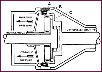 When the overdrive is engaged, a valve in the unit
is opened, applying hydraulic pressure from the pressure accumulator to two pistons which work in cylinders
formed in the unit housing. These pistons exert pressure against the
cone clutch member, overcoming the spring pressure and pushing the cone clutch
away from the annulus until the outer lining 'B' presses against a conical
brake ring 'A' built into the main casing of the gear box.
When the overdrive is engaged, a valve in the unit
is opened, applying hydraulic pressure from the pressure accumulator to two pistons which work in cylinders
formed in the unit housing. These pistons exert pressure against the
cone clutch member, overcoming the spring pressure and pushing the cone clutch
away from the annulus until the outer lining 'B' presses against a conical
brake ring 'A' built into the main casing of the gear box.
Figure 5. Schematic of overdrive
engaged.
The sun wheel, which carries on its splined
extension the cone clutch, is free to rotate on the driving shaft, there-fore,
when the cone clutch comes into contact with the brake ring, both cone clutch
and sun wheel are brought to rest and held stationary. The planet carrier 'C'
which is splined to the driving shaft is driven round the stationary sun wheel
so that the planets rotate and overdrive the annulus at a higher speed than the
driving shaft.
In overdrive, the outer member of the
roller clutch over-runs the inner member. Engine braking is again provided by
the cone clutch which holds the sun wheel from rotating in either direction.
Method Of
Operation
The change into or out of overdrive is made
without effort, and with perfect smoothness,
only the rise or fall in engine note
being noticeable, with resultant increase or decrease in engine noise
and vibration.
The use of overdrive claims to provide
considerable fuel economy, at least 10 per cent dependent upon usage and
circumstances, with additional saving in oil consumption and engine wear.
It is relevant to mention that the
overdrive gear may operate on top gear only, or on top and second gear, or top
and third – in a four speed box – as arranged in the original layout of the
vehicle.
There are also a variety of ways of
effecting the change into overdrive. One is direct through mechanical linkage,
the others with which we shall now concern ourselves are the electrical control
methods.
 Electrical Control
There are two forms of electrical control
in use, manual or automatic.
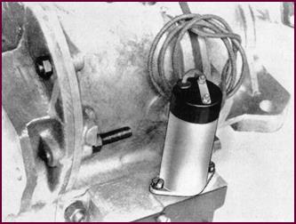 In either case, the principal unit is a solenoid switch,
which is featured in Figure 6, and is mounted on the side of the gear
box. Its function is simply to open and close the
hydraulic actuating valve for the overdrive gear change.
In either case, the principal unit is a solenoid switch,
which is featured in Figure 6, and is mounted on the side of the gear
box. Its function is simply to open and close the
hydraulic actuating valve for the overdrive gear change.
Figure 6. The Lucas TGS 1 overdrive
operating solenoid.
The various other components used on either
or both systems are concerned only with the control of this main solenoid.
We can now examine the simple form of
manually operated electrical control.
The Manually
Operated Electrical Control
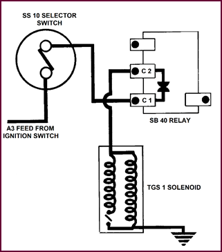
In this arrangement the main solenoid is
operated through a relay switch type SB40 which is itself actuated by two
separate switches.
 The current supply which is generally under the master
control of the ignition switch and is taken from the 'A3' terminal of the
ignition switch, is shown at the left of the circuit in Figure 7.
The current supply which is generally under the master
control of the ignition switch and is taken from the 'A3' terminal of the
ignition switch, is shown at the left of the circuit in Figure 7.
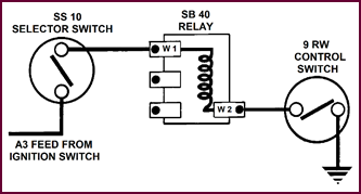
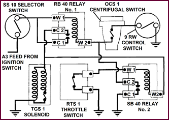
Figure 7.
Commencement – control switch circuit diagram.
A first requirement of the arrangement is
that the over-drive must not operate in reverse gear or in the first or first
and second gear of the 3 or 4 speed gearboxes respectively. The current supply
is therefore taken direct to a plunger type switch SS10 as shown on the left of
the diagram, which may be installed in the side of the gear box, or
alternatively linked to the gear change mechanism and operated by the gear
selector lever. This switch ensures that the circuit for the overdrive solenoid
is never complete unless the correct gear is selected.
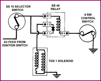
Figure 8. The circuit diagram from the
relay to the over-drive operating solenoid.
From the other side of this switch the
current is fed via terminals W1 and W2 of the relay windings through a
simple ON-OFF switch to earth.
The comparatively heavy current required to
operate the Solenoid itself, is switched by the main contacts of the relay at terminals C1 and C2. This current supply
provides a feed for both windings in the solenoid which are earthed. We
shall be dealing more fully with these 'Main' and 'Hold-on' windings later on.
Electric Manual
Control
 In Figure 9 we have the complete circuit for the
electric-ally operated manual control.
In Figure 9 we have the complete circuit for the
electric-ally operated manual control.
Figure 9. Complete circuit for manual
electric control.
To allow the overdrive to become operative,
the hand control switch 9 RW shown on the right of the diagram, must first be
closed.
 When top or the other prescribed gears are engaged, the
selector switch SS 10 will then also be closed, and current can pass through
the relay windings W1 and W2 to earth.
When top or the other prescribed gears are engaged, the
selector switch SS 10 will then also be closed, and current can pass through
the relay windings W1 and W2 to earth.
The Relay will then close contact C1 and
C2, allowing current to flow through the solenoid windings to earth; the
solenoid plunger will then lift and open the hydraulic valve which will engage
the overdrive gear, and it will remain engaged until either of the two switches
are re-opened.
The current supply to C1 terminal of the
relay is often taken direct from ammeter or main battery fuse.
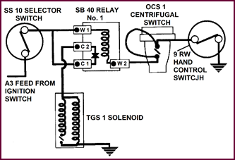
The Automatically Operated Electrical Control
 We can now deal with the Automatically Operated Elec-trical
Control.
We can now deal with the Automatically Operated Elec-trical
Control.
Figure 10. Circuit diagram illustrating
the automatically operated electrical control of the overdrive.
To achieve automatic changing into and out
of overdrive it is necessary to install firstly, a centrifugal or governor type
of switch which is driven from an extension of the Speedometer Drive Spindle.
In this component a single pair of contacts
are opened and closed by a governor at pre-arranged road speeds. In general
terms the governor closes the switch contacts at about 40 miles per hour (64
kilometres per hour) and opens them at between 30 to 35 miles per hour (48 to
56 kilometres per hour).
As shown in our picture this switch is
placed in the circuit between the W2 terminal of the No. 1 relay and the hand
control switch.
Thus, with the hand control switch in the
CLOSED position, the governor switch will operate the relay and engage and
disengage automatically. That is:
Change into
overdrive at about 40 miles an hour and;
Change back to
normal at about 30 miles an hour.
The centrifugal switch by itself will not
fulfil all the requirements, and it is necessary to introduce a further relay
operated by means of a switch linked to the accelerator pedal which we can now
consider.
Light Running
Conditions
When coasting at small throttle openings,
even at speeds below 30 miles per hour – when the centrifugal switch will be
open – it is not desirable to come out of overdrive unless it is required to accelerate
sharply, when the throttle will be opened up.
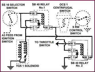
So, in order to keep the gear in 'overdrive'
under this Light Running Condition, a throttle switch linked to the accel-erator
pedal, together with an additional relay is introdu-ced. We shall refer to this
second relay, shown at the bottom right of Figure 11, as No. 2 relay.
Figure 11. Wiring circuit for light
running conditions.
The No. 2 Relay connected as shown – serves
to keep the No. 1 relay points CLOSED after the centrifugal switch contacts
have been opened. This No. 2 Relay will be energised when the throttle switch
is CLOSED, but as soon as the throttle switch is opened, the earth side of the
relay circuit is broken thus allowing the gear to change back to normal.
In brief, with the carburettor butterfly
and the THROTTLE SWITCH closed, the car will remain in overdrive.
With the throttle more than one fifth open
the switch will also be open and the car will return to normal gear until the
centrifugal switch contacts again close and changes it back into overdrive.
Figure 11 shows quite simply how the No. 2 relay
is added and connected to the No. 1 relay already in the circuit.
 The No. 2 Relay And The
Throttle Switch
The No. 2 Relay And The
Throttle Switch
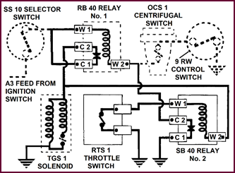
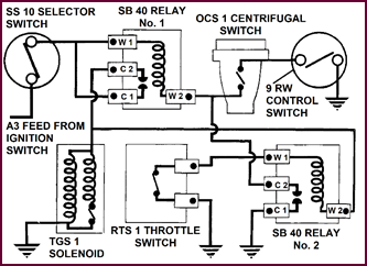
Figure 12. At lower right of the circuit
diagram are the added throttle switch and the No. 2 SB 40 relay.
Figure 12
shows the throttle switch added to the No. 2, relay and how the relay is placed
in the circuit.
Now try to follow this circuit through: the
conditions are that the car is run in overdrive at less than 30 miles per hour
with the gear selector and the control switches closed, and the centrifugal
switch open.
For this condition current is fed from the
C2 main contact of the No. 1 relay direct to the W2 terminal of the No. 2
relay, as shown at the bottom right, through the windings to W1 and thence across
the contacts of the throttle switch to earth.
In this condition the No. 2 relay is
energised, the contacts C1 and C2 will be closed, thus keeping the No. 1 relay
energised, and the hold-on current for the main operating solenoid will be
maintained irrespective of the centrifugal switch being open.
This condition will remain until such time
as the throttle is opened and the throttle switch contacts also opened, thus
breaking the current supply to the solenoid when the overdrive will change back
to normal drive.
Automatic
Operation
 Here we have the complete circuit of the automatic control
which you may wish to study before commencing on the next part.
Here we have the complete circuit of the automatic control
which you may wish to study before commencing on the next part.
Figure 13. The complete circuit for
automatic operation.
PART TWO: DESCRIPTION OF OVER-DRIVE CONTROL UNITS
The Electrical
Components
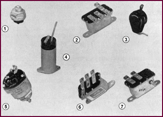
So far, we have built-up our overdrive
control, using the following components:
Commencing at the top left of the picture
for the 'Manual Control' System there are four units.
1. The Gear Selector Switch, type SS10.
2. The Relay type SB40 Relay.
3. The 'Hand' or 'Overdrive' Control Switch type 9RW.
4. The 'Transmission Gear Solenoid' type TGS1.
For 'Automatic' Control there are three
additional units :
5. The 'Centrifugal' Switch type OCS1.
6. An additional SB40 Relay.
7. The Rotary Throttle Switch type RTS1.
You will remember that the various switches
exist only to make the No. 1 Relay actuate the transmission gear solenoid under
differing conditions, and that this solenoid opens the hydraulic valve in order
to change the gears from 'Normal' to 'Overdrive' and vice versa.
 We can now examine these components individually.
Figure 14. Individual components
supplied by Lucas for the control of an overdrive.
Gear Selector
Switch Type SS10
 As previously mentioned this switch is usually the first
component in the current supply line and may be installed in the side of the
gear box.
As previously mentioned this switch is usually the first
component in the current supply line and may be installed in the side of the
gear box.
Figure 15. The gear selector switch.
Its function is to keep the overdrive gear
out of engage-ment, generally, in first and reverse gears.
In construction it is a simple ON-OFF
Plunger type switch. It is not a diaphragm switch and it is not oil proof.
At the same time oil passing through it
will not generally affect its operation.
Service troubles with this switch are
mostly due to incorrect setting of the external linkage, not providing sufficient
plunger travel to properly close the contacts.
It can easily be tested on or off the
vehicle by means of a Voltmeter or Lamp bulb across the contacts.
With Plunger
'out' switch should be open.
With Plunger
'down' the switch is closed.
Type SB40 Relays
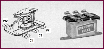 You may be aware that the general function of a relay
switch is to enable a current, particularly a fairly heavy current, to be switched
'on or off' from a remote position, thus minimising the voltage loss, generally
termed 'Volt Drop', which may occur.
You may be aware that the general function of a relay
switch is to enable a current, particularly a fairly heavy current, to be switched
'on or off' from a remote position, thus minimising the voltage loss, generally
termed 'Volt Drop', which may occur.
Figure 16. The Lucas SB40 relay.
The SB40 relay shown is a typical example
of this class of switch.
The main current supply is connected at the
C1 and C2 terminals, and terminates at the contact points as shown.
When the armature is drawn down on to the bobbin
core, the points close allowing a current to pass.
Terminals W2 and W1 are connected to the
ends of the relay coil winding as shown. A quite small current passing through
this winding creates a strong magnetic field in the core and pulls down the
armature, and so closes the main contacts which will remain closed for as long
as the relay coil is energised.
This model of the SB40 has been built
specially for the overdrive and the label 'Overdrive Relay' distinguishes it
from the model SB40 generally used as a horn relay, which is not suitable for
the overdrive, the main difference being that one is designed for continuous
working and the other for intermittent service only. Both the SB40 Relays used
on the overdrive are identical and interchangeable.
Normally these relays are practically
foolproof other than when the points become overheated and damaged, as may
result from an external short circuit.
They can be proved by two very simple
continuity tests.
1. For the Relay Windings.
2. To check continuity under load across the main contacts.
The Overdrive
Control Switch
Figure
17. A control switch for the overdrive.
This is a plain ON-OFF Switch, lever
actuated, and may be of various patterns according to the mounting position,
which is generally on the steering column or facia panel.
The
Transmission Gear Solenoid
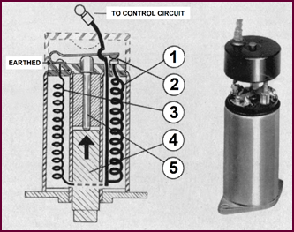 The transmission Gear Solenoid when energised is the
unit which brings about the change into and out of over-drive. As shown in Figure
18, the solenoid itself has two windings. A heavy, or closing winding shown
on the right '1', connected to EARTH through a pair of contacts '2'.
The transmission Gear Solenoid when energised is the
unit which brings about the change into and out of over-drive. As shown in Figure
18, the solenoid itself has two windings. A heavy, or closing winding shown
on the right '1', connected to EARTH through a pair of contacts '2'.
Figure 18. The Lucas TGS1 solenoid.
The hold-on winding is connected directly
to earth '3', as shown on the left. Both of these windings are in circuit when
the current is applied.
When the solenoid plunger '4' is pulled
into the coil the end of the plunger lifts the striker pin '5', and opens the
main winding contacts '2'. These contacts remain open whilst the plunger is in
the raised position thus keeping the main winding open circuited.
The heavy or closing winding requires 18 to
19 ampéres and is only in
circuit momentarily.
The hold-on-winding requires about 1 to 1·5
ampéres and is sufficiently
powerful to hold-up the Solenoid Plunger indefinitely. Point clearance and Air
gaps are pre-set and cannot be altered in service.
It will be realised at once that the
ingress of metal, dust, dirt, water or oil into the solenoid assembly can seriously
interfere with its operation and in the event of failure of this unit, wholly
or in part, this is the first thing to look for.
Transmission
Gear Solenoid Attachment – The Hydraulic Actuating Valve
We next come to the attachment and set-up
of the trans-mission gear solenoid to the gear box itself.
To ensure satisfactory operation, it is
necessary that the set-up of the solenoid to the gearbox is correct, and in the
event of trouble or during a re-setting operation this is the first thing to
check.
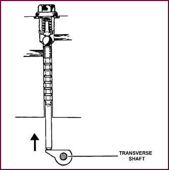
The Hydraulic Valve shown Figure 19
is actuated by a cam fixed to a transverse shaft running through the gearbox.
The Solenoid plunger operates through a lever attached to the other end of this
shaft. When the solenoid is operated this valve must be fully opened.
The Valve
Setting Lever
 With the solenoid energised, the setting of this valve
can be easily checked at the offside of the gearbox shown in Figure 20.
With the solenoid energised, the setting of this valve
can be easily checked at the offside of the gearbox shown in Figure 20.
Figure 19.
Operation of hydraulic valve by solenoid TGS1.
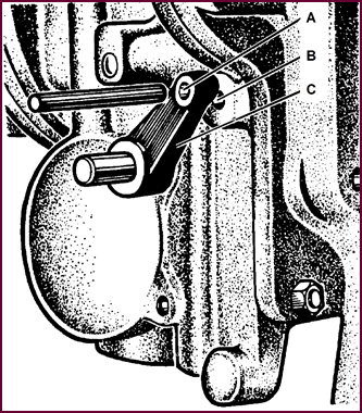 The end of the valve actuating shaft carries a short
lever 'C' with a 3/16" (4·76 mm) diameter hole
at the outer end, which should register with a similar hole in the casting as shown
at 'A' and 'B' (Figure 20). If it does so the valve setting is correct.
The end of the valve actuating shaft carries a short
lever 'C' with a 3/16" (4·76 mm) diameter hole
at the outer end, which should register with a similar hole in the casting as shown
at 'A' and 'B' (Figure 20). If it does so the valve setting is correct.
Figure 20. Checking the valve setting.
For the purpose of setting the solenoid
plunger – which we shall deal with later - a 3/16"
pin such as a drill shank – will be inserted to hold the valve in its correct
open position whilst setting the solenoid lever at the other side of the
gearbox.
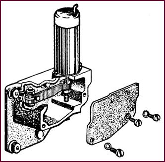
The Replacement
Of The Transmission Gear Solenoid
 If for any reason the solenoid has to be changed, the
original Plunger may be left in position provided that it is clean and free
from rust.
If for any reason the solenoid has to be changed, the
original Plunger may be left in position provided that it is clean and free
from rust.
Figure 21.
Replacement of the transmission gear solenoid.
In this circumstance it will be necessary
to check the setting for correct valve operation after fitting the new solenoid. To do this the following operations are
necessary:
1. Energise the solenoid.
2 Check the position of the valve setting lever, on the offside of
the overdrive unit, by inserting the 3/16" pin and if the holes
will not line-up the solenoid assem-bly must be re-set.
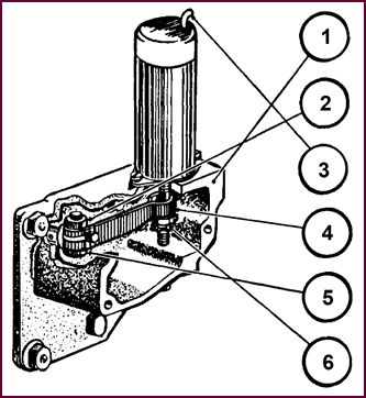
The Setting Of The Transmission Gear Solenoid
A complete re-set of the Solenoid assembly
is carried out in the following manner, Figure 22 refers.
Commencing with the 3/16"
pin in position (Figure 20) on the valve setting lever to hold the valve
open proceed to:
Remove the cover
plate '1'.
Loosen the lever
clamping bolt '2'.
Energise the
solenoid '3' (Check that the plunger travels the full movement).
Hold the lever
lightly against the plunger bolt head '4'.
Re-tighten the
lever clamping bolt '5' taking care to see that there is no end play in the
cross shaft.
Check the REST stop
clearance to ¼" (6·35 mm) '6'.
Remove the
locating pin from the offside of the gearbox.
Operate the
solenoid several times to check for correct working.
Note: A simple way to energise the solenoid
is to break the snap connector at the Solenoid terminal and connect with a
short lead direct to battery negative.
Figure 22. Setting the transmission gear
solenoid
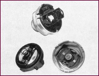
The Centrifugal
Switch
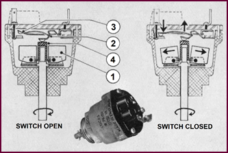 Figure 23. The centrifugal switch and its
operation.
Figure 23. The centrifugal switch and its
operation.
Driven from the speedometer take-off
spindle, this switch comprises two components:
An orthodox type
of flyweight governor '1' actuating a plunger shown at '4'.
A micro switch
movement '2' opening and closing a single pair of contact points, shown at '3'.
Increasing speed throws the weights
outwards and lifts the plunger, which in turn closes the micro switch con-tacts.
Thus switching ON the current to the Overdrive solenoid through the No. 1
Relay.
The points close at round about 800
governor r.p.m. This speed is pre-set and varies according to the model of
vehicle.
With falling speed, the points re-open at
80 per cent of the closing speed.
 In practice this means that the vehicle generally changes
to overdrive around the 40 miles per hour (64 kph) mark and returns to normal
gear round about 30 to 35 miles per hour (48 to 56 kph).
In practice this means that the vehicle generally changes
to overdrive around the 40 miles per hour (64 kph) mark and returns to normal
gear round about 30 to 35 miles per hour (48 to 56 kph).
A figure giving the closing revolutions of
the switch is stamped on one of the flats of the hexagon body.
If trouble is experienced in service,
several points can be looked to:
Damaged or loose
terminals which may result from contact with any external obstruction and may cause
erratic operation.
Terminals becoming
intermittently earthed, due to contact with the tunnel casing.
After removal of
the switch, check that it is being driven and for possible end float at the
spindle.
This should be about
0·002" and may cause erratic operation if excessive.
A further cause
of erratic running may also result from excessive vibration at the gear box
itself which the fitting of a replacement switch will not generally overcome.
These switches
are all pre-set at the works and must not be altered in situ. Also the
moulded top assembly should not be interchanged or the settings will be completely
upset.
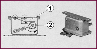
The Rotary
Throttle Switch
You will remember that the function of this
switch which is linked to the accelerator pedal, is to maintain current to the
overdrive solenoid by means of the No. 2 relay. This applies when the vehicle is running in top gear
below 30 miles per hour with the throttle CLOSED and the centrifugal switch
OPEN.
You will see in Figure 24 that the switch
comprises:
1. A pair of contacts on a spring blade.
2. A circular cam with a flat section, which is rotated by means of
a lever linked to the accelerator pedal. A spring is incorporated to return the
cam to its original position when the accelerator pedal is released.
 With the throttle closed, the points will also be closed;
when the cam is rotated the points will open and remain so until the throttle
is again closed.
With the throttle closed, the points will also be closed;
when the cam is rotated the points will open and remain so until the throttle
is again closed.
Figure 24. The rotary throttle switch.
It is a simple matter to check this switch:
1. See that the points are opening and closing.
This can be done by means of a voltmeter, or a Test Lamp
connected in series with the two terminals.
2. See that the rotating cam is correctly timed to the accelerator
pedal.
The correct setting of the cam is as follow
:
Referring to the extreme right of the Figure
24, the screw-driver slot in the end of the shaft should be horizontal with
the switch in the rest position.
The total movement of the cam is 90° and the contacts should remain closed for
the first 15° to 35° of rotation.
The Complete
Automatic Control
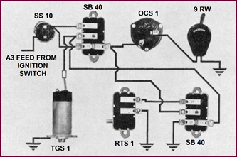 Finally, here is the pictorial diagram of the
complete Auto-matic Control from which it may be seen how simple the whole
arrangement is.
Finally, here is the pictorial diagram of the
complete Auto-matic Control from which it may be seen how simple the whole
arrangement is.
Figure 25.
The complete automatic control of the overdrive.
Legend:
SS 10 Selector Switch
SB 40 Relay No. 1
OCS 1 Centrifugal Switch
9 RW Manual Control Switch
TGS 1 Transmission Gear Solenoid
RTS 1 Rotary Throttle Switch
SB 40 Relay No. 2
You may perhaps like to study this and make
a copy of it for future reference.
PART THREE:
TESTING
Testing On The
Vehicle
Checking and testing of this equipment in situ
on the vehicle may be simply and easily carried out if the follow-ing
instructions are carefully followed when any defective unit or wiring will
show-up.
A quick overall test can be carried out
almost in a single operation without any special tools.
A full diagnosis test can be done with a
simple test volt-meter and ammeter.
Fault Finding
Guide
We shall deal primarily with faults which
may develop on the vehicle in service. The chart shown here lays out the kind
of symptoms which may be met and, as you will see, those concerning the
electrical equipment are a minority.
From the chart it will be seen that there
are five main items:
No. 1. Overdrive
Does Not Engage
Electrically this may be due to the
solenoid operating lever adjustment or any other electrical defect.
No.2. Overdrive
Does Not Release
Electrically this may also be due to
incorrect solenoid plunger and operating lever adjustment, or some other
electrical defect.
No.3. Clutch
Slips In Overdrive
Again this may be due to incorrect
adjustment of the solenoid operating lever.
No. 4. Clutch Slip
In Reverse Or Free-wheel Condition In Overdrive
As auto-electricians we are not concerned.
No. 5. Overdrive Engages
Overdrive engages in the normal manner but
when the Throttle is CLOSED should the speed drop below that at which the
centrifugal switch contacts open a return to normal gear accompanied by a heavy
braking effect, occurs.
This trouble will be primarily due to
incorrect setting of the throttle switch lever, or it might be a faulty No. 2
relay.
The test routine that we shall specify will
cover in a few simple operations anything that can happen to the electri-cal equipment
under all of the headings shown, which is all that the electrician is concerned
with.
Fault Finding Chart
(Set Out Below)
Note: It appears that this procedure
chart has been taken from a vehicle manufacturer's service manual for a car
model equipped with an overdrive unit. That is why, very likely, there are
non-electrical procedures shown here. These are shown in blue text, black text
is Lucas content.
No. 1 – Overdrive Does Not Engage
Insufficient oil in
unit.
Check solenoid operating lever adjustment. Check
the electrical system.
Check operating valve.
No oil pressure.
No. 2 – Overdrive Does Not Release
Check operating
valve.
Check electrical system.
Check solenoid plunger and operating lever
adjustment.
Check for sticking
cone clutch.
No. 3 – Clutch Slips In Overdrive
Check oil in unit.
Check solenoid operating lever adjustment.
Check for low
hydraulic pressure.
No. 4 – Clutch Slip In Reverse Or Free
Wheel Con-dition In Overdrive
Check restriction in
valve jet causing sluggish operation of cone clutch.
NO. 5 – Overdrive Engages: With Throttle
Closed A Return To Normal Gear, With A Heavy Braking Effect, Occurs As Speed
Diminishes
Check for correct setting of rotary throttle
switch (RTS1) lever. Check electrical system.
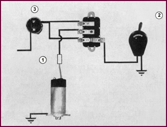 Checking The Manually
Operated Electrical Control
Checking The Manually
Operated Electrical Control
Figure 26. Procedure for checking the
manually operated electric control.
Let us first deal with the hand operated
electrical control – the simpler of the two. Irrespective of any specific complaint
which may be made, a quick and simple overall test of workability can be
carried out in three operations, after removing the floor casing to gain
access:
1. Switch ON the ignition (Item 1, Figure 26l).
2. Close the hand control switch (Item 2) and engage top gear, thus
closing the gearbox selector switch contacts (Item 3).
If the system is working the solenoid will immediately operate
and open the hydraulic valve.
Check this visually by observing the movement of the valve
setting lever on the offside of the gearbox, when the two 3/16"
pin holes should register.
This proves immediately that:
The current
supply is on.
The gearbox
switch is closing properly.
The hand control
switch is closing properly.
The relay main
contacts and operating windings are both working.
That the main
solenoid is also operating.
Lastly, from an
observation of the valve setting lever we shall
know that the Hydraulic Valve is being fully opened.
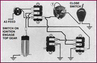
Checking The
Automatic Control System
We can next apply a similar check to the automatic
system in four operations. With the vehicle stationary and the engine stopped,
proceed to:
Switch on the
ignition.
Close hand
control switch and engage top gear.
Link the
terminals of the centrifugal switch as shown at (Item 1, Figure 27).
Then:
If the system is
operative, the main solenoid will be raised and will remain in this position.
Check the correct
'Open' position of the valve setting lever on the offside of the gearbox.
This simple operation of linking the
terminals of the centrifugal switch proves:
1. The current supply is ON.
2. The gearbox switch is closing properly.
3. The hand control switch is closing.
4. That the main solenoid is operating.
5. That the hydraulic valve is opening fully.
If, when the link is removed, the solenoid plunger is still
held, we also prove:
6. The main contacts and relay winding of both relays are
operative.
 7. That the throttle switch is closed.
Figure 27. Checking the automatic
control system.
Test Procedure
If the equipment fails to operate when the
foregoing checks have been carried out, it will be necessary to make a
methodical fault diagnosis.
This can most easily be done in three
stages:
Stage 1. The
circuit comprising – the SS10 switch, the hand control switch, the No. 1 relay
and the main solenoid.
Stage 2. The
circuit including the No. 2 relay and the throttle switch.
Stage 3. A
test for the centrifugal switch and the main solenoid.
This is equally applicable to the manual
circuit and represents the complete test for it.
Stage 1 Test
To Test the SS10, the Hand Control Switch,
the No. 1 Relay and the Main Solenoid.
(A)
This test is carried out in six operations
as follows:
With the engine stopped and the car
stationary. Switch on the ignition.
Select top gear, thus closing the SS 10
gearbox selector switch
Bridge the terminals of the centrifugal
switch (if automatic control).
Close the hand control switch. If the
current is normal the main solenoid will come into operation and remain in the
raised position.
 Check the position of the valve setting lever
(off-side of the Gearbox).
Check the position of the valve setting lever
(off-side of the Gearbox).
Figure 28. Circuit diagram for Stage 1
test.
(B)
If the Solenoid fails to operate, proceed
to:
Break the snap connector at the Solenoid
and energise it repeatedly by means of a jump lead direct from the battery
negative terminal.
If the solenoid proves to be in order:
Open the hand control switch and check
through for full voltage readings with the negative voltmeter at the following
points:
Across both terminals of the SS10.
Between – W1, W2 and C1 terminals of the
No. 1 relay respectively and earth.
Between live side of the hand control
switch and earth.
Close hand control switch when the voltage
reading should fall to zero if the switch and earth line are in order.
The No. 1 Relay should then close and a
voltage reading should be obtained at Contact C2 (No. 1 relay) and also at the
end of the solenoid feed wire. If no voltage is obtained at C2, the relay is
defective.
 Stage 2 Test
Figure 29. Circuit diagram for Stage 2
test.
The part circuit, comprising the No. 2
relay and the throttle switch.
Still with the ignition switch on and top
gear engaged, remove the bridged lead from the centrifugal switch.
Link terminals C1 and C2, of the No. 2
relay when the solenoid should come into operation and remain in the raised
position.
If no operation when the C1 and 2 terminals
are linked, check relay No. 2 for a good earth connection to C1 terminal, or
for a broken wire between the W2 terminal of No. 1 relay and C2 terminal of No.
2 relay – put in order.
On the removal of the link between C1 and
C2 terminals after the solenoid has closed, the solenoid should remain raised
and return to normal rest position when the accel-erator pedal is depressed.
If, when removing the link, the solenoid
returns immed-iately to the rest position and does not hold, check the throttle
switch setting also link the C1 and C2 terminals again then with a voltmeter
check for a voltage at the W2 terminal of the No. 2 relay. If in order,
transfer the volt-meter lead to W1 terminal and with the throttle switch open
voltage will be registered if the relay winding is in good order and voltage
reading will disappear when the throttle switch is closed proving the switch
circuit is com-plete to earth.
If not put in order.
Stage 3 Test –
Control Switch And Solenoid
To check the operation of the Centrifugal
Switch and the solenoid.
Jack-up the back wheels.
Open the push-in connector adjacent to the
solenoid and insert the test ammeter in this line.
Start up the car and engage top gear.
Increase engine speed and the centrifugal
switch should close at slightly above 40 m.p.h. The main solenoid should then
close with a surge of current and the ammeter should remain at 1 to 1½ amps.
showing that the 'hold-on' coil is operative, and the main winding cutting out.
If a heavy current of about 20 amps registers continually, it will probably be
necessary to check the solenoid which will have become overheated.
Immediately check the valve setting lever
as shown on Page 9.
Document
Restorer's Note
Once again, the course session stresses
the requirement for good earthing contacts. This is particularly so when
carrying out the recommended tests.
Observe Domestic Science notions – keep
earth contacts clean and soundly tight.
Mike
Allfrey.
Jowett
Car Of Australia Inc.