PART ONE:
WINDSHIELD
WIPERS (MODEL C.W.)
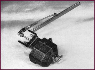
The CW Wiper –
External View With Arm And Blade
The type CW wiper is widely used as an
accessory as well as initial equipment on certain models of vehicles.
Available in THREE models for both 12 and 6-volt
work-ing the model CW1 is supplied for top of screen mounting and the CW2 for
BOTTOM screen mounting.
The CWX is built as a universal model for
either top or bottom fixing and can be advantageously stocked as a general
service replacement.
 Control is obtained by means of an on-off switch and
parking handle which form an integral part of the unit. Covers are designed to
provide parking of the blades on either side of the screen.
Control is obtained by means of an on-off switch and
parking handle which form an integral part of the unit. Covers are designed to
provide parking of the blades on either side of the screen.
Figure 1.
External view of Model CW windshield wiper.
The popular
arrangement is a 'three' hole fixing. The spindle
emerges centrally and the motor is held by two studs one on either side.
Packing pieces and adaptor blocks are
available. The latter when fixed to the motor enables the assembly to become
'single' hole fixing.
The normal wiping angle may be either 130° or 150° but models with special angles
have been produced to suit vehicle makers' requirements.
The wiper arm and squeegee are fixed to the
spindle by means of a quickly detachable split collet incorporated in the boss
of the wiper arm.
There is a range of both arms and
squeegees, the latter varying from 6" (152 mm) to 9" (229 mm) in
length to suit different size screens.
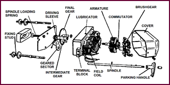
The
Construction Of The CW Wiper
Figure 2
will give you an idea of the construction of the CW model. The motor assembly
is on the right and the gearing on the left.
 We shall be examining both of these sections in greater
detail later.
We shall be examining both of these sections in greater
detail later.
Figure 2.
Exploded view of the Model CW wiper assembly.
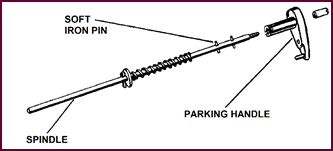 The Safety Device
Figure 3. Location of soft iron
shear-pin.
One feature of the unit is not generally
known, and that is that the motor is provided with a safety device against
shock. A small soft-iron pin, passing through the motor spindle, forms the
driving member. This pin shears if for some reason the spindle is prevented from
turning with the motor still taking current. The shearing of the pin prevents the
motor from burning out, or stripping some of the teeth in the gear wheels.
Now for a closer examination of the motor
itself.
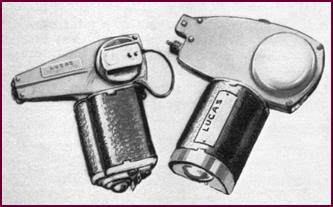
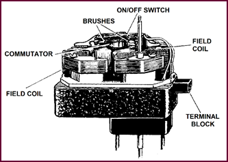 The CW Motor
Figure 4. Major components of the Lucas
CW motor.
The motor consists of a three-pole armature
running in a two-pole shunt wound field. The two field coils are wound on
laminated iron formers and connected in series, pro-ducing two magnetic poles.
The armature comprises a laminated iron core
carrying three windings, thus forming three magnetic poles.
Field and armature windings are in parallel
with one another.
The ends of the windings are brought out to
a terminal block on the right. The internal ON/OFF switch is built onto the
brush gear, the operating lever being part of the cover assembly.
The CW Circuit
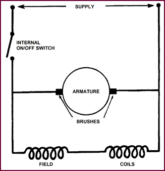 The current feed passes via this internal ON/OFF switch,
through the brush gear to the commutator, round the armature windings and back
to the other side of the supply. Both field coils are connected in parallel
with the armature.
The current feed passes via this internal ON/OFF switch,
through the brush gear to the commutator, round the armature windings and back
to the other side of the supply. Both field coils are connected in parallel
with the armature.
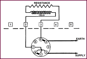
Figure 5. Circuit diagram for Lucas CW
motor.
The supply will generally be taken from the
'A4' fuse to one side of the motor terminal block and from the other terminal
on this block back to the 'E' terminal at the Control Box.
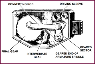 The Gearing
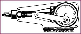
Figure 6. Inside the CW gear casing.
A small driving gear is fixed to the one
end of the armature spindle. Let us now see how the drive is trans-mitted from
this point to the wiper arm, which, in the driving position, is engaged to the
driving sleeve.
The drive is first taken up by the
intermediate gear and transmitted by a pinion to the final gear. A connecting
rod is pivoted eccentrically on this gear, converting the rotary movement with
the help of the geared sector into the reciprocating movement necessary for the
wiper arm. This drive is transmitted to the arm and blade when the parking switch
is moved and the spindle engaged with the driving sleeve. The soft-iron pin we
mentioned earlier is the actual engaging member.
Waterproofing
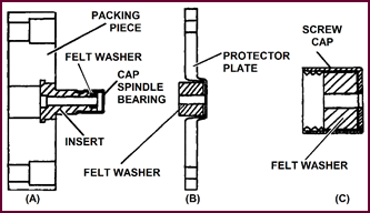 All wipers in the CW range are provided with adequate
means for protecting the mechanism against the entry of water past the wiper
spindle. The necessary felt and cork inserts are provided with the unit and
must be used if the wiper is to give long and trouble free service.
All wipers in the CW range are provided with adequate
means for protecting the mechanism against the entry of water past the wiper
spindle. The necessary felt and cork inserts are provided with the unit and
must be used if the wiper is to give long and trouble free service.
Figure 7. Methods of preventing ingress
of water.
We show several methods here of sealing the
wiper spindle, and additional protective 'Langite' gaskets are available for waterproofing
the fixing stud holes.
Fitting Up And
Maintenance
No maintenance in the general sense is
required in service. The gearbox is packed with Duckhams KEENOL KG25 grease at
assembly. A spring ball lubricator is prov-ided for the long armature bearing and
a small quantity of oil may be inserted occasionally.
Care should be taken when setting up a new
wiper to see that the water excluding devices are properly seated. If water
should gain ingress to the gearbox the emulsified grease must be cleared out
and the gear box re-packed.
Also when fitting up a new wiper the
current supply should be taken from the 'A4' fuse, or in any earlier type of
car installation, from the Ignition Switch in order that the supply is
automatically cut-off when the ignition is switched off.
Service Faults
The most common faults in service will be
sheared driving pins resulting from shock load such as fouling the blade when
cleaning the screen and bent spindles, causing seizing and overheating of the
motor. Noisy operation usually is caused by general wear and tear.
Ingress of water causes loss of lubricant by
emulsification and usually results from incorrect fitting.
Low torque will be due to worn brushes or
bearings.
Normal current consumption:
12-volt 1·8 to 2·5 amps.
6-volt 3·0 to 4·0 amps.
Stall current consumption:
12-volt 2·7 to 4·0 amps.
6-volt 4·4 to 5·5 amps.
Heavy current consumption will indicate
internal binding, or this fault may also be due to excessive pressure on blade
to screen or spindle binding in screen aperture.
Low current reading will probably be due to
worn brushes, or a dirty and greasy commutator.
If ammeter test readings are unsteady
suspect defective armature windings or a faulty commutator.
General Method
Of Testing In Position
Connect ammeter in circuit and switch on
the wiper, take current reading.
If no current flows check the 'A4' fuse.
Using a voltmeter across the leads, check the supply from the wiper termin-al
block.
If voltage supply is normal but no current
flowing, remove wiper for examination and service.
If no voltage at terminal block, the supply
or earth return circuit is defective.
WINDSHIELD
WIPERS (Model C.R.)
Model CR Wiper
And Wheelbox Assembly
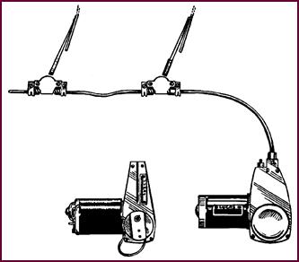
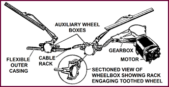 Figure 8, gives a
general view of the CR type wiper, showing how the drive from the motor is transmitted
to the wiper blades by means of a flexible rack and wheelboxes. There are two
models, CR and CRT. The CR series covered by Model Nos. 1 to 7 provide a variety
of wheelbox and switching assemblies together with a range of varying angles of
wipe. The model CRT is similar to the CR, but incorporates a thermostatic
overload switch which functions to stop the motor if, for any reason, the
maximum safe working temperature is exceeded as a result of prolonged overloading.
Figure 8, gives a
general view of the CR type wiper, showing how the drive from the motor is transmitted
to the wiper blades by means of a flexible rack and wheelboxes. There are two
models, CR and CRT. The CR series covered by Model Nos. 1 to 7 provide a variety
of wheelbox and switching assemblies together with a range of varying angles of
wipe. The model CRT is similar to the CR, but incorporates a thermostatic
overload switch which functions to stop the motor if, for any reason, the
maximum safe working temperature is exceeded as a result of prolonged overloading.
Figure 8. Schematic drawing of the Model
CR system.
The motor and gear box are mounted under
the bonnet, whilst the wheelboxes are fitted
at the bottom of the screen.
The drive to the wiper arms is obtained by
means of a cable rack, comprising Bowden type cable over wound with a wire
helix. This wire helix acts in the same manner as the teeth in an ordinary
rack, and engages with the gear wheel attached to the wiper drive spindles
mounted on the wheelboxes. The cable rack, as you can see, is enclosed in a
flexible metal outer casing.
These motors are made for both 12 and 6-volts
working; the motor and its reduction gearing exerts a push of approximately 50
lbs. (22·7 kg) on the cable rack.
General
Arrangement
 Sundry arrangements have been provided in order to
fulfil the various requirements of the vehicle manufacturer.
Sundry arrangements have been provided in order to
fulfil the various requirements of the vehicle manufacturer.
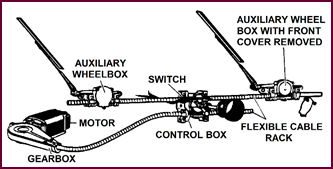
Figure 9. The general assembly with
control box.
In the one illustrated the wiper control
box is mounted centrally – or may be off-set if required. It performs the dual
function of simultaneously switching the motor on and off, and parking the
blades at either end of the screen as may be desired.
 An Alternative
Arrangement
An Alternative
Arrangement
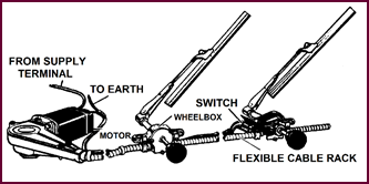
Figure 10. Provision for hand parking of
either blade.
The arrangement illustrated in this picture
provides for hand wiping and parking of either blade independently, the 'on and
off' switch being incorporated in the wheelbox on the driver's side.
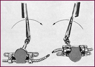
Opposed Wiping
Arcs
In both the above arrangements the
wheelboxes are mounted over the cable rack, thus producing a parallel motion of
wiper blades. If it is required to operate the arms towards each other, i.e.,
'Clap Hands' arrangement, one of the wheelboxes will be mounted above the rack
and the other one below it. Then, in order to obtain the desired angle of sweep
it may be necessary to install a crank wheel with a different throw in the
motor itself.
Figure 11. The setup for opposed wiping
arcs.
Wheelboxes:
 Assemblies And Methods
Of Fixing
Assemblies And Methods
Of Fixing
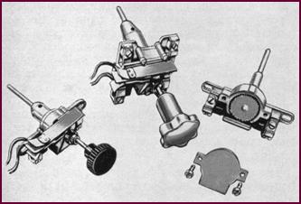
Figure 12. Typical wheelboxes and their
mountings.
There are one or two other features of the
CR and CRT wipers which might be of interest.
Figure 12 shows a close-up of one of the earlier
type wheel-boxes used. It should be noticed that the
two slotted ears are used for the fixing screws to the scuttle of the car, and
two half clamps are installed to locate and hold the ends of the flexible outer
casing of the cable rack.
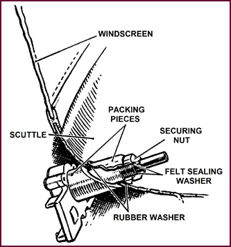 Wheelbox – Single Hole
Fixing
Wheelbox – Single Hole
Fixing
Figure 13. The single hole fixing
wheelbox.
Another type
of wheelbox assembly provides for single hole fixing by means of a securing nut
as shown in Figure 13.
In order to make this arrangement adaptable
to existing scuttle angles, several different sloping packing pieces and suitable
rubber washers have been produced to suit individual vehicles.
Wiper Arm
Fixing
This illustration shows a collet
arrangement for fixing the wiper arm to the wheelbox spindle.
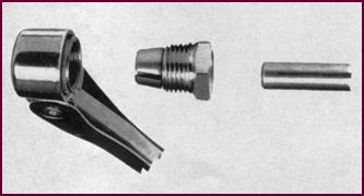 Several different versions of this system have been in
use for many years.
Several different versions of this system have been in
use for many years.
Figure 14. The tapered split cone nut
for fixing arm to wheelbox spindle.
The CR Motor
And Gear Box Assembly
The drive from the motor armature to the
cable rack is obtained by means of a double reduction gear of approximately 72:1.
The first stage reduction of 13:1 is obtained by means of a worm cut on the end
of the armature spindle which engages with a worm wheel. This worm wheel is built
integrally with a spur pinion; the pinion engages with the final drive gear wheel,
as shown, at a ratio of 61:11. A crank pin and connecting rod then trans-mits
the drive to the crosshead on the cable rack. The number
of wipes per minute will be approximately 90-100.
Figure 15. Section and cover removed
view of motor and gearbox assembly.
It should be noted that, altogether, six
different wiping angles ranging from 105° to 150° are now used on the different
makes of vehicles. The varying length of stroke being obtained by altering the
throw of the crank. Thus to alter the angle of wipe it is necessary to change
the final gear wheel in the gear box.
The silent running of this gearing can be
maintained if the correct type of grease is used; that is, Duckham's Keenol
KG25.
The Eccentric Type Shunt Motor-Magnetic Circuit
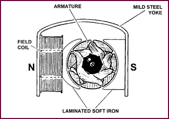 Commencing with the magnetic circuit of the motor it
will be seen that the 'field' is provided with one coil only situated on one
side of the armature. The 'U' shaped yoke of mild steel which forms part of the
body of the unit completes the magnetic circuit, bringing the opposite
polarity, the south pole in our illustration, to the other side of the
armature.
Commencing with the magnetic circuit of the motor it
will be seen that the 'field' is provided with one coil only situated on one
side of the armature. The 'U' shaped yoke of mild steel which forms part of the
body of the unit completes the magnetic circuit, bringing the opposite
polarity, the south pole in our illustration, to the other side of the
armature.
Figure 16.
The eccentric type shunt motor magnetic circuit.
Incidentally, this type of construction is
generally styled as an eccentric motor, the armature being off-set from the
centre as shown.
Sectioned Motor
In this cut-away section the actual layout
is clearly shown.
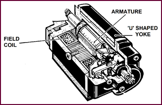 You can see that the armature is mounted
eccentrically in the body with the field coil at the side of it, and the 'U' shaped
yoke surrounding both components. Otherwise, the motor is of the plain shunt wound
type, with the single field coil in parallel with the armature windings.
You can see that the armature is mounted
eccentrically in the body with the field coil at the side of it, and the 'U' shaped
yoke surrounding both components. Otherwise, the motor is of the plain shunt wound
type, with the single field coil in parallel with the armature windings.
Figure 17. The Lucas CR wiper motor,
sectioned view.
By contrast with the CW type wiper the 'on
and off' switch is a separate unit.
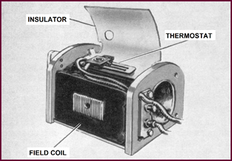
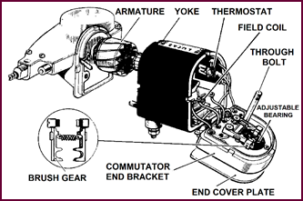
The Overload
Cut-Out Switch
The CRT wiper incorporates a thermostatic
cut-out switch as shown in this illustration, and this is the model now fitted
to a great number of current production vehicles.
The fitting of the thermostatic switch in
the original CR model was not necessary as the stall current of the motor was not so heavy. The CRT model, however, develops
much greater power with a correspondingly higher stall current.
Figure 18. Location of the overload
cut-out switch.
Some form of temperature control was thus required
to protect the windings against overload. Excessive current draw, with
consequent overloading, can be caused by packed snow or ice on the windscreen,
or by 'binding' of the wiper spindles due to bad fitting – in fact by anything
which unduly strains the motor.
The
Thermostatic CRT Wiper
The thermostatic switch is connected in the
supply line to the motor and automatically breaks the circuit when the temperature rises to between 90° and 95 °C (194-203
°F).
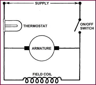 The switch will re-close automatically when the temperat-ure
of the motor falls to around 60 °C (140 °F), which is the ordinary running
temperature.
The switch will re-close automatically when the temperat-ure
of the motor falls to around 60 °C (140 °F), which is the ordinary running
temperature.
Figure 19.
Circuit diagram for the thermostatic CRT wiper.
Thus, operation of the thermostatic switch
will stop the motor without warning and it might remain so stopped for several
minutes, i.e., until the motor temperature drops, when it will re-start and
continue at normal speed provid-ing the main switch is left in the 'on'
position.
CR And CRT Armatures
And Field Coils
 The armature illustrated on the left of Figure ??
is that used on the original CR wiper and is built with a steel thrust ball
inserted in the commutator end of the spindle as shown.
The armature illustrated on the left of Figure ??
is that used on the original CR wiper and is built with a steel thrust ball
inserted in the commutator end of the spindle as shown.
The armature of the CRT model has a greater
number of turns of wire in each of the seven armature slots and provision for
thrust is made in a slightly different way with the result that a plain end
shaft is used, as shown on the right.
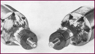 Therefore, these armatures are NOT interchangeable.
Figure 20. The CT and CRT armatures and
field coils.
Also, the field coils are not interchangeable.
Self-Aligning
Bearings
A novel feature of both the CR and CRT
wiper motors is the self-aligning commutator end bearing as shown in the
illustration.
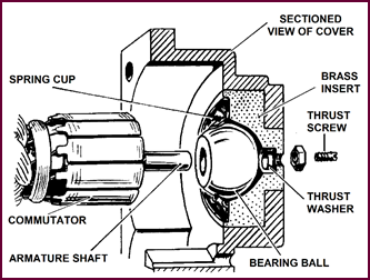 The bearing itself is a ball, held in position by a spring
cup as shown, thus ensuring that the armature is lined up with the front end
bearing, and the thrust screw at the back.
The bearing itself is a ball, held in position by a spring
cup as shown, thus ensuring that the armature is lined up with the front end
bearing, and the thrust screw at the back.
Figure 21. Showing the placement of the
bearing.
This thrust screw is necessary by reason of
the worm drive on the other end of the armature, and should be set so that the
end float is just sufficient to allow the shaft to rotate freely.
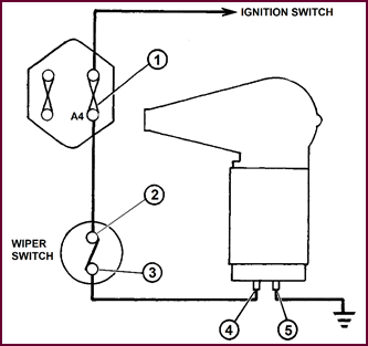
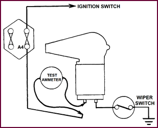
Wiring Circuit
And Fault Finding
It is general practice to wire the
screenwiper circuit through the A4 fuse, thus providing master control from the
Ignition Switch; the object of this is to prevent the wiper motor being left in
the ON position when the vehicle is out of use, with the consequent danger of
running the battery down.
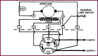
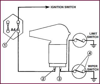
Figure 22. Procedure for fault finding.
The typical circuit arrangement using a 14/·012
strand green master colour cable is shown here.
 Electrical faults may be easily located by means of
a voltmeter, and overloading, with consequent sluggish operation, by means of
an ammeter.
Electrical faults may be easily located by means of
a voltmeter, and overloading, with consequent sluggish operation, by means of
an ammeter.
In every case testing should commence with
the obvious external possibilities such as
defective Fuse or Fuse Clips, loose connections or defective switch, loose
connections at the wiper motor and defective earth connections.
The whole systematic check should proceed
in the order given.
Start at point 1, the A4 fuse, one of the
most likely trouble spots in the circuit. A quick check can be made by switch-ing
on first the ignition and then any other auxiliary fed from this fuse – for instance
trafficators, stop lights, etc.
If none of these are operating, check the
fuse. If this is intact, the supply to it can be checked with a voltmeter
between the terminal and earth.
If a reading is obtained at A4, next check
at the wiper switch. Voltage should be shown between either terminal and earth
with the switch closed – i.e., at points 2 and 3 in our illustration.
Point 4 is the next at which a voltage
reading should be shown. A zero reading should be obtained between point 5 and
earth. If any reading is shown, examine the earth connection.
Wiring Circuit
And Fault Finding (2)
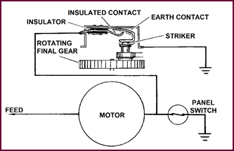
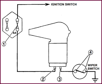 In the circuit we have just examined you will notice
that the switch is on the 'live' side of the motor.
In the circuit we have just examined you will notice
that the switch is on the 'live' side of the motor.
Figure 23.
Fault finding procedure for earth control switch.
Alternatively, and quite frequently, it may
be installed in the earth side as shown in this Figure 23.
The checking procedure is similar but the
order of the voltage checks differs. The order in this case will be: point 1,
the A4 fuse; point 2, the motor supply terminal – at both points voltage should
be registered.
With the wiper motor switched on, there
should be no voltage reading between point 3 and earth; nor between either of
the switch contacts and earth.
Current Consumption
Test
The normal running currents for these
motors are a good guide to performance.
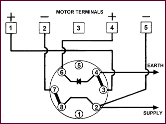
Figure 24. Diagram for current
consumption test.
Excessive current readings will indicate
that over-loading exists at one of the following points:
1. Excessive blade pressure on the screen.
2. Binding at the spindles and wheel-boxes.
3. Binding at the rack or outer casing.
4. Partial seizure or other fault in the motor assembly itself.
An ammeter placed in the wiper feed as
shown will give an immediate indication of any of these troubles which may then
be localised, firstly, by removing the arms and blades and lastly, by
disconnecting the motor assembly from the rack and trying the unit by itself.
Abnormally low current readings will, if
the voltage is properly maintained, indicate that the motor brushes are either
worn out or sticking, or if a heavy reading is accompanied by excessive drop in
voltage, a short within the motor itself will be indicated.
Normal Current
Consumption
|
Motor
Cold – Driving Both Blades On Wet Screen
|
|
|
CR –
Amps.
|
CRT –
Amps.
|
|
6-volt Version
|
3·5
to 6·0
|
4·0
to 6·5
|
|
12-volt Version
|
1·75
to 3·0
|
2·0
to 3·25
|
Normal Currents With Cold Temperature
The correct current readings with a cold
motor driving both blades on a wet screen should be as shown in the tabulation,
above.
Once the trouble is located to the motor
assembly, an inspection can then be made, and any small faults such is dirty
commutators, worn brushes, sticking brush levers or loose connections can be
conveniently rectified without necessitating the exchange of any major
components.
The opportunity should be taken to open the
gearbox cover and, if necessary, re-pack the wiper with the correct grease,
Duckham's Keenol KG25.
After correction the motor should be
re-tested. The cur- rent taken should then
be back to normal and the specified speed of 90 to 100 oscillations per minute obtained.
Maintenance And
Fault Finding
Very little maintenance is required to keep
windscreen wipers in a serviceable condition.
All the moving parts are packed with grease
before leav-ing the factory, and if periodic attention is paid to these other
points, trouble-free service can be expected.
Make sure that the wiper motor fixing, and
that of the wheelboxes is secure.
The next point follows from the previous
one: if the wheel-boxes have moved slightly, the spindles will tend to bind in
the apertures, putting an undue strain on the motor.
 The next concerns the rubber of the wiper blades, which
should be inspected occasionally, and the blades re-placed after long service.
The next concerns the rubber of the wiper blades, which
should be inspected occasionally, and the blades re-placed after long service.
Figure 25. The three maintenance points
are important.
Dirt and grease tend to accumulate on the
rubber and harden. This impairs the 'squeegee' action of the blade, making
clean wiping of the screen impossible.
Wiper Arm
Fixing
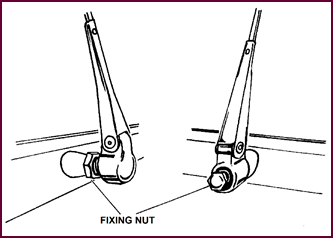 If slipping of the wiper arm occurs, the trouble can
usually be traced to the collet fixing. The hexagonal nut should be firmly
tightened after the blades have been set to give the correct wiping arc on the
screen.
If slipping of the wiper arm occurs, the trouble can
usually be traced to the collet fixing. The hexagonal nut should be firmly
tightened after the blades have been set to give the correct wiping arc on the
screen.
Figure 26. At left the collet nut is
tightened into the arm to firmly grip the spindle. At right the collet nu is
tightened into the arm from the front.
At the same time, check that the hinge
spring in the arm is not weak or broken.
Blade Fixing
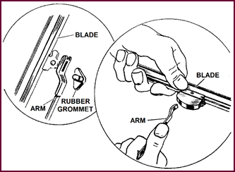 And here are two of the usual methods in use for
fitting the blades.
And here are two of the usual methods in use for
fitting the blades.
Figure 27. Attaching the blade to the
wiper arm.
In the left-hand illustration, the rubber
grommet secures the blade, whereas on the right it is held in position by a
spring clip.
Both fixings permit side-movement or
rocking of the blade, ensuring maximum contact with the screen over the full
wiping angle.
WINDSHIELD WIPERS (Models DR1 And DR2)
The DR1 And DR2
Wiper Motor Assemblies
The DR series of complete Dual wiper
assemblies are the latest additions to the Lucas range and are now being widely
applied to current production vehicles of all makes.
 There are two basic types, the DR1 which may be for
either single or two speed working, and the DR2 single speed. Both models,
which are made for 6, 12 or 24-volts are substantially more powerful than the earlier
CR types.
There are two basic types, the DR1 which may be for
either single or two speed working, and the DR2 single speed. Both models,
which are made for 6, 12 or 24-volts are substantially more powerful than the earlier
CR types.
Figure 28. Left, DR2; right DR1.
The two-speed arrangement has been
developed spec-ially for high speed vehicles which may be subjected to any conditions
up to the proverbial tropical downpour.
Both of these wipers are so far arranged
for automatic self-parking and are controlled by means of switches mounted on
the facia panel.
The DR1 uses a rotary 3-position switch,
and the DR2 a simple push and pull, 'on and off' switch.
The DR1 And DR2
General Assembly
 The layout of cable rack, casing, wheelboxes, arms and
blades follow the general pattern of the CR with certain differences.
The layout of cable rack, casing, wheelboxes, arms and
blades follow the general pattern of the CR with certain differences.
Figure 29. The DR1 and DR2 general
assembly.
In order to provide for the increased power
it has been necessary to substitute the flexible metallic outer casings by
rigid steel 'Bundy' Tubes. This is a ductile steel tube with a coppered lining
and is attached to the motor and wheelboxes by 'flaring' the ends, and connecting
to the motor by means of a 'union' type connection, and to the wheelboxes by means
of clamp plates.
The wheelboxes themselves are cast
assemblies on the DR1 model, and steel pressings on the DR2.
 The Rack Drive Assembly
Figure 30. The rack drive assembly, the
outer casing for the rack is virtually rigid.
A more detailed consideration of the
wheelbox, motor and outer casing assembly is desirable.
Trouble free service is contingent upon the
free running of the rack within the wheelboxes and the tube.
This illustration of the Bundy Tube layout
will show clearly how necessary it is to have correct alignment throughout.
Flattened sections or kinks in the rigid tube will cause binding and consequently
overloading of the motor and care must be exercised when fixing the assembly.
Misalignment of any of the components is
also liable to cause binding, the junction of the motor assembly to the Bundy
tube being one of the most vulnerable points.
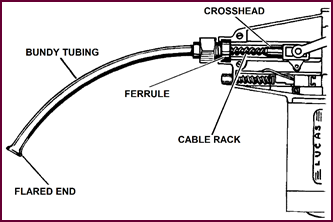 The Rack
Drive And Attachment Of The Bundy Tube
The Rack
Drive And Attachment Of The Bundy Tube
Figure 31. Schematic of Bundy tube
attachment.
As seen on the left of the picture, the
Bundy tube is 'flared' for attachment by the clamp plates to the wheelboxes.
The drive-end fixing, centre, is a 'union' type attachment.
The flexible rack connects to the motor
crank by means of the cross-head shown.
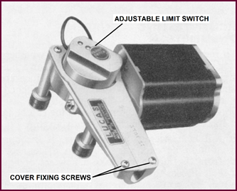
Parking adjustment is made by means of the
limit switch with which we shall deal in detail at a later stage.
Wheelboxes
Whilst following the general pattern of the
CR type wheel-boxes, the clamping arrangement varies in order to fix the Bundy
tube properly.
Figure 32. DR1, left, and DR2, right, wheelboxes..
The DR1 wheelbox shown on the left is of
die-cast con-struction, and, as you can see, the flared end of the Bundy tube
is located in the special recesses positioned between the rack wheel and the
clamping plates.
The DR2 pressed steel wheelbox, on the
other hand, uses the cover for clamping the Bundy tube in position.
The DR1 wheelboxes may be single hole
fixing similar to the CR type, or may be located by means of two separate
fixing screws as shown on the left.
The DR2 wheelbox in the picture on the
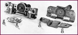
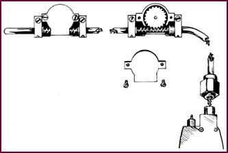
right is a one-hole fixing type only.
DR2 Wheelbox
Bundy Tube Location
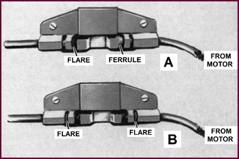 On the early production DR2s a ferrule brazed to the
Bundy tube on the primary length from motor to wheelbox was arranged to locate
in the space next to the rack wheel as shown at 'A ' in Figure 33.
On the early production DR2s a ferrule brazed to the
Bundy tube on the primary length from motor to wheelbox was arranged to locate
in the space next to the rack wheel as shown at 'A ' in Figure 33.
Figure 33. Bundy tube fixings to
wheelboxes.
On later production the use of the ferrule
was discontin-ued and the end of the tube
'flared out'. The correct position of the flare is then in the narrow space as
shown at 'B'.
In the lower picture it can be observed
that the flare on the inter-connecting section of tube may also be located in
the narrow space, but this is immaterial.
Wiper Arm
Fixing
 Another departure from the earlier CR arrangement is
the method of locating and locking the wiper arm on to the wheelbox spindle.
Another departure from the earlier CR arrangement is
the method of locating and locking the wiper arm on to the wheelbox spindle.
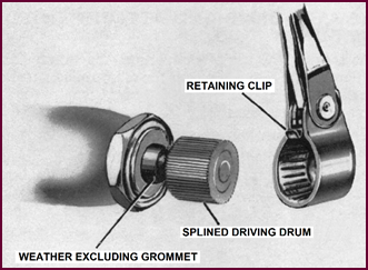
Figure 34. Fixing the wiper arm to the
wheelbox spindle.
In both the DR1 and DR2 a splined drum is pressed
on to the wheelbox spindle, and mates with the splined hub of the wiper arm.
The arm is locked by means of the retaining
spring clip as shown. In order to remove the wiper arm it is only
necessary to lift the spring clip by means of any small lever and withdraw the
complete arm.
It should be noted that the splines are arranged
at 5° intervals to enable the arm to be placed in any desired parking position.
It may also be noted that the wheelbox
spindle is grease packed on assembly, and embodies a weather excluding grommet
as shown.
The DR1 Motor
Assembly
We may now examine the DR1 motor and
gearbox assembly. To summarise the characteristics of this TWO speed arrangement:
1. It is produced for 6, 12 and 24-volt working.
2. Has 'Normal' wiping speed of
90 to130 wipes per min-ute and in the 'High' speed 130 to 150 wipes per minute.
3. The high speed is obtained by weakening the motor field by means
of a resistance inside the motor, and a combination switch mounted on the
facia.
4. The angles of wipe will vary between 90° and 130° as specified
by the vehicle manufacturer.
5. Parking is available at either end of the stroke as may be
desired.
 6. A thermostatic cut-out switch built
into the motor is provided to prevent damage
if persistently overloaded for any reason such as heavily packed snow or ice.
6. A thermostatic cut-out switch built
into the motor is provided to prevent damage
if persistently overloaded for any reason such as heavily packed snow or ice.
Figure 35.The DR1 wiper motor assembly.
DR Gear Mechanism
This view of the inside of the DR1 gear box
shows the gearing. In some ways it is simpler than either the CW or the CR
wipers.
A worm cut on the end of the armature
spindle engages with the worm wheel as shown, Providing a reduction ratio of 42·5
to 1. This worm wheel in turn mounts the crank pin which connects directly to
the crosshead of the driving rack. A screw type adjustable Thrust Pad for the
worm spindle will be seen at the top.
A self-parking switch is located at the
bottom left and is adjustable for exact
parking position by means of the screw and knurled nut shown on the
extreme left. This parking switch is actuated by a striker fixed to the
crosshead.
Figure 36.
Schematic of DR motor, gears, connecting rod and crosshead assembly.
The Self-Parking
Mechanism
Let us now make a closer examination of
this self-parking device. The requirements are that the wiper blades park automatically
on whichever side of the screen may be determined by the vehicle manufacturers,
and also they can be adjusted to stop at any desired position in relation to
the bottom of the screen.
To do this, a simple blade type switch 'A'
is located in a slide as shown.
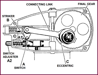 With the motor running normally the striker roller 'B'
on the crosshead will NOT come into contact with the switch blade 'A1',
located below the crosshead.
With the motor running normally the striker roller 'B'
on the crosshead will NOT come into contact with the switch blade 'A1',
located below the crosshead.
Figure 37. Schematic of self-parking
mechanism.
To stop and park the wiper blades the first
operation is to reverse the direction of the motor by means of the main switch
on the facia panel inside the car.
When reversal of the motor rotation
commences an ec-centric cam 'C' on the crank pin causes the driving rack
to move further outwards than when running normally.
 The striker roller 'B' on the crosshead then contacts
the switch blade 'A1' and stops the motor. This stoppage will always
take place at the end of the stroke.
The striker roller 'B' on the crosshead then contacts
the switch blade 'A1' and stops the motor. This stoppage will always
take place at the end of the stroke.
The exact stopping position is determined
by means of the adjusting screw shown at 'A2' and this adjustment can be
varied at any time in service.
If the wiper blades are to be parked on the
opposite side of the windscreen two things are necessary.
Firstly, the motor armature connections
must be changed over and secondly the switch assembly 'A' must also be
changed over. That is, with the blade 'A1' facing inwards towards the
final gear.
The Eccentric
Cam
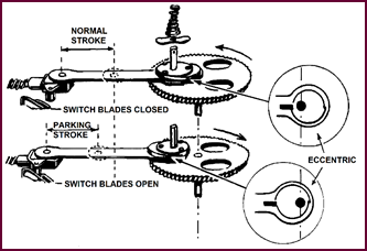 This illustration shows in some detail the eccentric
cam between the crank pin and the connecting rod.
This illustration shows in some detail the eccentric
cam between the crank pin and the connecting rod.
Figure 38. Showing the operation of the
eccentric cam.
The top picture illustrates the normal
stroke path of the connecting rod which is coupled to the driving rack.
When the panel switch is moved to the
'Park' position, the direction of rotation of the motor is reversed. The eccen-tric
cam as shown in the lower illustration moves through half a revolution, and the
stroke path of the connecting rod will then be moved along sufficiently for the
striker on the crosshead to open the contacts of the Limit Switch and thus stop
the motor.
Arrangement Of
Opposite Parking Positions
Figure 39. Arrangements of opposite
parking positions.
The top illustration clearly shows the
layout of the 'Parking' or 'Limit' switches for stopping the wiper either on
the left or right hand side of the screen, also the knurled nut for setting the
final at-rest position in relation to the bottom of the screen.
The smaller illustration gives a fair idea
of the switch assembly itself, the latest model on the left having the end of
the blade extended by comparison with the early type.
The DR1 Motor
 The main features of this motor, both magnetically and
electrically are similar to that of the CRT model which has already been
reviewed. It is an eccentric machine, the armature being offset from the
centre. The field is provid-ed with one coil only, located below the armature.
The 'U' shaped yoke of mild steel, which forms part of the body of the unit
completes the magnetic circuit, bringing the opposite polarity, the south pole,
to the other side of the armature.
The main features of this motor, both magnetically and
electrically are similar to that of the CRT model which has already been
reviewed. It is an eccentric machine, the armature being offset from the
centre. The field is provid-ed with one coil only, located below the armature.
The 'U' shaped yoke of mild steel, which forms part of the body of the unit
completes the magnetic circuit, bringing the opposite polarity, the south pole,
to the other side of the armature.
Figure 40. The DR1 motor.
The armature itself is supported at the
commutator end by a self-aligning bearing of the type used in the CR model.
There is also a bearing bush between the motor and gearbox, and at the outer
end of the shaft an adjust-able stop is provided to control end movement.
A thermostat wired in series with the
armature is mounted on the inside of the yoke near to the second pole-piece. It
consists of a bi-metal strip and contacts, which open when the temperature rise
becomes excessive. In this way the motor is protected against overload.
An additional component is the resistance
which is con-nected into the field to produce the speed increase for the High
Speed wipe. This is over-wound on the motor field coil, and is brought out to
the terminal board on the C.E. bracket as we shall see.
The DR Wiper
Motor Circuits
As a simple commencement to a study of the
circuits of the DR1 wiper arrangement we may trace through the motor circuits
only.
The motor itself may be considered to have
four circuits:
1. The Armature Circuit;
2. The Field Circuit;
3. The Field with resistance in circuit;
4, The Limit Switch circuit.
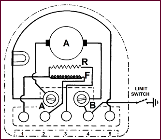 Commencing at the armature circuit the current path
is from Terminal '5' through the thermostat switch to the brush terminal
'A', through the armature to brush terminal 'B', finishing at
terminal '4'.
Commencing at the armature circuit the current path
is from Terminal '5' through the thermostat switch to the brush terminal
'A', through the armature to brush terminal 'B', finishing at
terminal '4'.
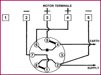
Figure 41. The Model DR wiper motor circuits.
The field circuit – from terminal '2'
to one end of the Field Coil, through the field returning to terminal No. '1'.
The field with
resistance in circuit – from terminal '2' through the field coil to the junction point with the resistance, and from
the other end of the resistance to terminal '3'.
The gearbox limit switch is placed in the
earth side of the motor circuit, and is as shown from terminal '4' through
the switch contacts.
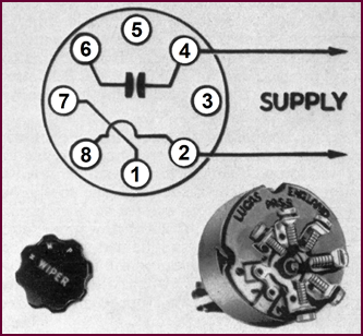 The PRS5 Switch
Figure 42.
The PRS5 switch assembly.A specially designed
Rotary Switch arranged for single hole fixing – panel mounting – called the PRS5
provides three positions:
1. 'N' – 'ON' for normal running speed.
2. 'H' – 'HIGH SPEED' Wiping.
3. 'P' – The parking position.
This comprises two components :
Firstly, a rotor with two contact segments
which select the various running positions, and secondly a cam actuated contact breaker – a pair of points – which makes
and breaks the motor's earth connection for starting and stopping.
 We have already stated that the motor may be consid-ered
to have FOUR internal circuits, and we can now state that the motor, the
switch, and the current supply and return comprise three circuits:
We have already stated that the motor may be consid-ered
to have FOUR internal circuits, and we can now state that the motor, the
switch, and the current supply and return comprise three circuits:
1. From the supply through the switch when in the 'N' position.
2. From the supply through a different combination of connections
for the 'H' position.
3. From the supply through a further combination of connections for
parking and stopping.
Circuit No. 1 –
Normal Running Position
Switching to the 'N' position starts
the wiper with the blades moving at normal speed.
 The current supply is connected to the No. '2'
terminal at the control switch. Here it divides, one path to the armat-ure, the
other to the field. Remember it is a shunt-type machine, with the two circuits
in parallel.
The current supply is connected to the No. '2'
terminal at the control switch. Here it divides, one path to the armat-ure, the
other to the field. Remember it is a shunt-type machine, with the two circuits
in parallel.
Figure 43. Switch set to normal running
position. Terminal '3' connected to terminal '4', and terminal '7' connected to
terminal '8'. The contacts 'C' are closed.
We will deal with the armature circuit
first. The supply is taken from terminal '2' of the switch to terminal '5'
at the wiper motor. Then it continues via the thermostat through the
brush at 'A' to the armature; the return is from the other brush at 'B'
to motor terminal '4', which connects to No. '6' at the switch. A
pair of contacts, marked 'C', closed internally by the switch in the 'N'
position, completes the circuit via terminal '4', to earth.
Now the field circuit: Starting from
terminal '2' at the control switch which is permanently linked to '8',
the switch rotor position for normal running connects to '7'; the
circuit path is then to No. '2' on the motor through the field to No. '1'.
From No. '1' then to No. '3' on the switch, across the other
rotor contact to No. '4' and then to earth.
This circuit provides for screen wiping at
normal speed.
High Speed
Position
On switching to the 'H' position,
high speed wiping is obtained.
This is brought about electrically by the
insertion of a res-istance in series with the field coil. You remember we
pointed out this resistance winding on the field coil a few pages back. It has
the effect of reducing the field current and hence the field strength of the
motor. With the field strength reduced, the armature turns at a faster speed.
Figure 44. Circuit diagram for high
speed. Switch in high speed position; terminal '9' connected to terminal '1',
and terminal '4' connected to terminal '5'.
It should be realised that this increase of
wiping speed is only obtained by a corresponding reduction in the motor torque.
This in turn is compensated by a reduction in the wiper blade load due to the
heavy flooding of the windscreen surface such as occurs in exceptionally heavy
rain, tropical downpour, etc. If the high speed wipe is maintained under normal
conditions of loading, the motor will
eventually overheat and the thermostatic switch will finally stop it completely
and it will remain stopped until the motor temperature again falls to normal.
Remembering that the armature circuit
remains unchang-ed, now follow out the field circuit with its resistance in series. Commence from the switch supply terminal
No. '2'. The current path is via the fixed link to '8',
through the rotor segments to '1', through another fixed link to '7',
direct to field terminal '2' on motor, through the field and its
resistance to motor terminal '3'. From there it passes to switch '5'
through rotor segment to '4' direct to earth.
The Parking
Position
This circuit shows the control switch
turned to the 'P' or park position. The motor switches off, and the blades
park automatically.
As far as the electrical side of the
operation is concerned, the field circuit is momentarily reversed; that is, the
feed is in the opposite direction. The supply
is now switched via terminal '2' and '3' of the control
switch to the No. '1' terminal of the field winding, as opposed to No. '2'
for 'normal' running. Current will thus flow in the reverse direction through the
field circuit, reversing the rotation of the motor, but current will only flow
as long as the earth side of the circuit is complete. The contacts 'C'
in the control switch are open in this position, the only available earth being
provided through the gearbox limit switch. You can follow this from No. '2'
terminal of the field winding, through switch terminals '7' and '6'
and on via 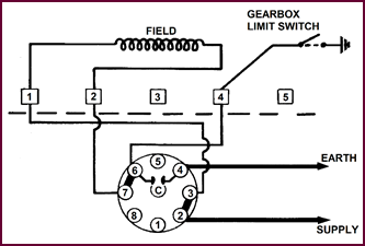 terminal '4' at the motor, to the limit switch
and earth.
terminal '4' at the motor, to the limit switch
and earth.
Figure 45. Switch in Park position.
Terminal '2' connected to terminal '3', and terminal '7' connected to terminal
'6'. Contacts 'C' are open.
If this switch contact is now broken, the
motor will stop.
Circuit Testing
Stage 1.
The Normal Running Position
Having examined the motor and switch
circuits, we can now formulate a simple routine for testing either or both.
Assuming that our problem is an electrical
one, the first thing is to localise the trouble to either the motor, the
switch, or the wiring.
To do this the following procedure is
recommended:
1. Check the current supply to the circuit. Commencing from the A4
fuse, this can easily be checked with the voltmeter.
 2. Turn the switch to NORMAL running position.
With the voltmeter, take readings at the wiper motor term-inal block. We should
expect to find full voltage readings between terminals '1' and '2'
(Field) and terminals '4' and '5' (Armature).
2. Turn the switch to NORMAL running position.
With the voltmeter, take readings at the wiper motor term-inal block. We should
expect to find full voltage readings between terminals '1' and '2'
(Field) and terminals '4' and '5' (Armature).
Figure 46. Testing – switch in 'Normal'
position.
This will indicate that the switch itself
and its wiring to the motor is in order in the 'N' position. If a LOW
voltage reading is obtained at the Armature terminals '4' and '5'
it suggests that the motor is taking excessive current and will generally necessitate
its removal. If 'No Voltage' is obtained from terminals '1' and '2'
or '4' and '5' we can assume that an open circuit exists either
in the switch, or its wiring, which can be traced by following the circuit
shown in Figure 46.
Circuit Testing
– Stage 2.
The High Speed Running Position
 Having checked the wiring and switch for the 'Normal'
running position, we can now move to the HIGH SPEED position of the switch.
Having checked the wiring and switch for the 'Normal'
running position, we can now move to the HIGH SPEED position of the switch.
Figure 47. Testing – switch in 'High
Speed' position.
For this condition we should have full
voltage at terminals '2' and '3' (Field Resistance) and '4'
and '5' (Armature) of the motor terminal block.
If NO VOLTAGE is obtained at either pair of
terminals an open circuit exists in the switch or the wiring.
Circuit Testing
– Stage 3.
 The Parking Position
Figure 48. Testing – switch in 'Park'
position.
We can now check the circuit with the
switch in the PARK position, which will also check the operation of the limit
switch:
1. Connect voltmeter to terminals '1' and '2' (Field)
at motor terminal block.
2. Turn switch to NORMAL position – Voltage reading should be
obtained.
3. Turn switch onwards to the PARK position when polarity at
terminals '1' and '2' will be reversed, the motor rotation will
reverse and then the wiper will PARK at the end of the stroke.
If upon changing the switch from NORMAL to PARK
the motor stops with no voltage readings at terminals '1' and '2',
check the LIMIT SWITCH circuit and the EARTH to the motor body itself.
The circuits we have just examined are
applicable to the DR1 wiper motor only. We can now turn to the more recent type
DR2 motor and its circuit.
 The DR2 External View
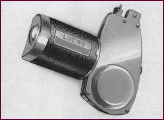
The DR2 is the new model in the DR range,
being basic-ally similar to the DR1, and designed to give approxim-ately the same performance. It is suitable for 6,
12 and 24-volt working, with varying angles of wipe from 90° to 130°.
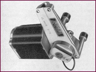 The models so far fitted to vehicles are constructed
for single speed operation only.
The models so far fitted to vehicles are constructed
for single speed operation only.
Figure 49. The Lucas DR2 motor assembly.
The DR2 is not thermostatically controlled,
since the motor is designed to withstand stall currents for a con-siderable
time.
A different arrangement for self-parking
allows a simple ON/OFF panel control switch to be used.
 DR2 Internal View –
Gearbox
DR2 Internal View –
Gearbox
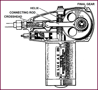
Figure 50. DR2 gearbox, internal view.
Internally, the construction is very
similar to the DR1. An eccentric type motor drives a single nylon final gear
through a helix on the end of the armature shaft. Then the design becomes
simpler than the DR1; there is no ec-centrically mounted connecting link to
give self-parking. Instead, a plain link transmits the reciprocating movement via
the crosshead and cable rack to the wheelboxes. As with the DR1, the rack is
housed in 'Bundy' tubing.
Self-Parking
Arrangement
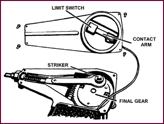
Self-parking of the wiper blades is brought
about by mov-ing a simple panel control switch to the 'OFF' position. With the
switch in this position, the motor stops at the end of the wiper arm stroke by
virtue of the limit switch shown here, which as you can see is built into the
detachable cover of the gearbox. The contact arm of this switch is operated by the head of the crank pin which is an
integral part of the final gear. This striker opens and closes the con-tacts
once every complete revolution of the gearwheel.
Figure 51. Limit switch for self-parking
operation.
Limit Switch
Circuit
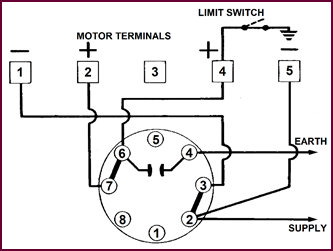
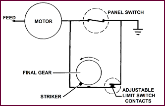 This diagram will serve to illustrate the method of oper-ation
of the Parking Switch.
This diagram will serve to illustrate the method of oper-ation
of the Parking Switch.
Figure 52. The limit switch circuit.
Consider the current path from the motor to
EARTH.
With the panel
switch CLOSED the motor circuit is comp-leted. In order
to park automatically a parallel current path and switch is placed in the
circuit. To stop movement both of the switches must be open.
In order to stop the operation at any
desired position of the stroke, the panel switch is first moved to the 'OFF'
position thus breaking one current path. At the end of the stroke a striker
operates the blade of the limit switch, which will continue to open and close
at each revolution of the crank; this will not interfere with the operation
whilst the panel switch remains in the 'ON' position.
The panel control switch, when in the 'OFF'
position, breaks the earth side of the motor circuit, the only remain-ing path
to earth being a parallel one through the limit switch contacts. Thus the motor
stops when these contacts are opened.
Limit Switch
Construction
 The construction and operation of the LIMIT switch
will be apparent from this illustration.
The construction and operation of the LIMIT switch
will be apparent from this illustration.
Figure 53. Limit switch construction.
Two spring blades are connected to the
motor and the switch respectively as shown at the top, and are in con-tact
until separated by the striker located in the head of the final drive wheel
crank pin.
The Limit
Switch Adjustment
 The limit switch is adjustable, enabling the correct
parking position to be obtained.
The limit switch is adjustable, enabling the correct
parking position to be obtained.
Figure 54. The limit switch adjustment.
The switch assembly is released by
slackening off the four gearbox cover fixing screws. It should then be turned and
set so that the motor switches off just after the blades have finished their
downward travel and are starting the upward stroke.
It must, however, be remembered that this
limit switch is correctly adjusted on the assembly line and re-adjust-ment
should not normally be necessary.
Servicing The DR2
Wiper:
Circuit Testing
– Voltmeter Test
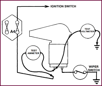
Switch on the ignition and ascertain that
current is available at the A4 fuse. This can be easily checked by the
voltmeter. With the wiper motor switched 'OFF' we should also have full voltage
readings at the wiper motor terminals '2' and '3' Figure 55.
At the same time when the wiper switch Item '4' is moved to the 'ON' position
the voltage registered at '3' should disappear. If it does not, the
wiper switch itself or the earth point is faulty.
Figure 55. The DR2 voltmeter test.
If no voltage is registered at the points
mentioned it is a simple matter to trace the open circuit by following the
wiring sketch shown.
The voltage tests must be supplemented by
current con-sumption tests as we shall now show.
Normal Current
Consumption
|
Motor
Cold – Driving Both Blades On Wet Screen
|
|
|
DR1 –
Amps.
|
DR2 –
Amps.
|
|
6-volt Version
|
5·0
to 7·3
|
5·0
to 6·3
|
|
12-volt Version
|
2·4
to 3·5
|
2·5
to 3·0
|
|
|
(Normal
Running)
|
|
Thermostat
Switch Temperatures:
Opens:
135° to 150 °C (275° to 302 °F)
Closes: 80 °C (176 °F) Minimum
|
DR1 And DR2
Performance Data
The correct technical data as shown above
will be a very good guide in the event of any unsatisfactory perform-ance. For
instance, any mechanical overloading will be reflected at once by abnormally
heavy current consum-ption by the motor, with possible persistent overheating
which may cause damage.
Equally, the approximately correct voltage
readings are an infallible guide to defective fuses, wiring, terminals or earth
connections.
To take a simple example: Full voltage test
readings, and zero, or very low current readings, would indicate at once badly
bedded brushes in the motor, burnt commutator, of worn out brushes.
You will notice that the thermostatic
switch is not fitted to the DR wiper.
On the DR1 this switch will cut out the
operation if the motor temperature rises to between 135° and 150 °C (275° and
302 °F), and it will remain open until the motor temperature falls to 80 °C
(176 °F), which may take several minutes according to under-bonnet and general prevailing
conditions. It should be apparent that if the wiper switch is left in the 'ON'
position the motor will re-start automatically.
Circuit Testing
– Current Consumption
 To measure the current consumption whether the motor
in question is the DR1 or the DR2, an ammeter is inserted in the A4 feed (Green)
to the wiper motor, as shown in our sketch. With the motor switched on, the
reading shown will fluctuate slightly as the squeegee load varies, but a mean
reading can be taken and checked against the chart already given.
To measure the current consumption whether the motor
in question is the DR1 or the DR2, an ammeter is inserted in the A4 feed (Green)
to the wiper motor, as shown in our sketch. With the motor switched on, the
reading shown will fluctuate slightly as the squeegee load varies, but a mean
reading can be taken and checked against the chart already given.
Figure 56. Circuit Testing, current
consumption.
It will be necessary at this stage, if the
current consump-tion appears very high, to disconnect the rack from the motor
and take a new set of figures. We shall discuss this in more detail.
Servicing The DR1 And DR2 Wiper Assemblies
From the service point of view the
following conditions of unsatisfactory performance may be met:
1. Sluggish operation or complete seizure:
Of the several possible reasons for this condition the most
likely one is that of a greasy and fouled screen.
Another is partial seizure of the driving rack resulting from
misalignment of the assembly, or kinking or dis-tortion of the Bundy tubing.
Lastly, the trouble may rest in the motor and gearbox assembly
itself.
In each case an
excessive current will generally be taken by the motor in its effort to drive
the blades at normal speed.
2. Electrical Faults:
True electrical faults are
very infrequent but if they do occur they must obviously be either in the motor
assembly, the wiring, or the switch, as distinct from the external mechanical
faults to which reference has just been made and which may be sufficiently
serious to damage the motor electrically if allowed to persist.
A methodical approach to fault diagnosis is
essential if the CAUSE of any unsatisfactory performance is to be tracked down.
Test Procedure
And Fault Finding
Sluggish operation or seizure, usually
indicated by exces-sive current consumption may be caused by:
a. Low Voltage due to defective connections, partic-ularly earth
connections.
b. Cable Rack bind in the Bundy Tubing.
This may result from
flattening, kinking, or over sharp bends; should be 9" (229 mm) minimum
radius).
c. Excessive wiper blade loading due to fouled or greasy screen.
d. Wheel-box misalignment or spindles seizing in the bearing
housing.
e. Mechanical or electrical faults in the motor and gearbox
assembly.
To diagnose the cause of any of these
troubles proceed as follows:
1. Connect a test ammeter and voltmeter in circuit as shown in Figure
56, on this page.
a. Connect test ammeter in series with wiper feed lead (Green).
b. Connect test voltmeter across the green lead terminal of wiper
and earth.
2. Switch-on the motor and check for low voltage.
Should be 11·5-volts minimum. If lower, examine the fuse,
re-make main and earth connections sound as necessary.
3. Remove both wiper arm and blade assemblies.
4. Switch on the motor and test for current consumpt-ion and speed
of stroke.
|
6-volts
|
12-volts
|
|
DR1 5·0 to 7·3 amps.
|
2·4 to 3·5 amps.
|
|
DR2 5·0 to 6·3 amps.
|
2·3 to 2·9 amps.
|
|
Cycles
Per Minute
|
|
DR1 Normal Speed: 90 to 98 (15 to 16
in 10 secs.)
|
|
DR1 High Speed: 132 to 148 (22 to 25
in 10secs.)
|
|
DR2 Normal Speed: 90 to 100 (12 to 17
in 10 secs.)
|
If the current
take and the speed of operation is now correct the fault lies with a fouled
screen.
If the current reading remains excessive:
5. Remove wiper motor gearbox cover and disconnect the driving
crank from the crosshead as follows:
a. On DR1 Motors, remove the cotter-pin securing the connecting rod
to the final gear and withdraw the connecting rod complete with eccentric coupl-ing,
conical spring and friction plate.
b. With DR2 wipers, first remove the gearbox cover and secondly the
circlip securing the connecting rod to the final gear. The connecting rod can
now be lifted out.
6. With the cable driving rack now disconnected, switch on and test
the motor independently, taking a current reading and also a re-count of the
number of strokes of the crank pin.
If it is then found to be correct we can safely assume the
trouble to be in the rack and Bundy tube assem-bly, or the wiper spindles and
wheelboxes.
If the speed is still low replace the motor
assembly or check following points:
a. Armature binding due to thrust screw being out of adjustment.
b. Commutator end bearing out of alignment.
c. Short circuit on commutator due to carbon dust, etc.
To Check The Bundy Tube, Driving Rack And Wheel Box Assemblies
 Sluggish operation or seizing in service is
frequently caused by misalignment of the assembly or binding of the driving
rack in the Bundy tube.
Sluggish operation or seizing in service is
frequently caused by misalignment of the assembly or binding of the driving
rack in the Bundy tube.
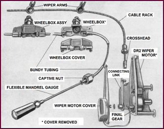
Figure 57. The Bundy tubes, wheelboxes
and drive rack.
To test for correct cable rack clearance in
the tube pro-ceed as follows:
If binding exists, the sections of the
Bundy tube must be examined. To do this:
1. Remove arms and blades.
2. Remove wiper motor cover.
3. Extract connecting link between crosshead and final gear.
4. Withdraw cable rack.
5. Remove wheelbox cover.
Insert the Mandrel, which should move
freely through each section of tube.
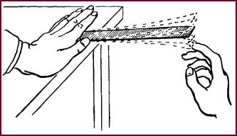
If the bind is caused by flattening of the
tube at a turn it may be possible to clear it by gently reforming the tube
carefully in a vice.
If a 'kink' exists, the complete section of
tube will have to be replaced.
In some cases an emergency repair can be
carried out by filing away the 'kinked' section by means of a suitable size
half-round file. Care should be taken to remove frays from the cut-away edge of
the bore, and also wash out all filings and lubricate all moving parts with
Duckham's H.B.B. grease.
PART TWO: HIGH FREQUENCY HORNS
Working
Principles
As the purpose of any horn is to produce an
audible warning of approach, we must necessarily first spend a little time in
examining the nature of sound and how it originates, before we discuss any of
the modern pro-duction units.
The Production
Of Sound Waves
 Sound, as we know it, is the result of disturbing
the air. All of you at some time must have been familiar with the effect
produced by flicking a strip of metal held at one end. All that we are doing is
disturbing the air, setting it in rapid motion in the immediate vicinity of the
strip. The disturbance set up by such mechanical vibrations are transmitted in
wave form through the air. The human ear is capable of detecting these 'sound
waves', rendering them audible.
Sound, as we know it, is the result of disturbing
the air. All of you at some time must have been familiar with the effect
produced by flicking a strip of metal held at one end. All that we are doing is
disturbing the air, setting it in rapid motion in the immediate vicinity of the
strip. The disturbance set up by such mechanical vibrations are transmitted in
wave form through the air. The human ear is capable of detecting these 'sound
waves', rendering them audible.
Figure 58. Vibrating a metal strip to
produce sound.
Examination Of
Wave Form
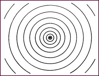 We can best illustrate how sound waves travel through
the air by likening them to the waves produced on the surface of water when a
stone is dropped into it.
We can best illustrate how sound waves travel through
the air by likening them to the waves produced on the surface of water when a
stone is dropped into it.
Figure 59. Waves of sound move in a
circular pattern, outwards from the source of the disturbance.
Waves or ripples travel out in a regular
circular pattern from the source of disturbance, decreasing in effect as they
move outwards.
Striking A Gong
Similarly, when a gong is struck, the
mechanical vibra-tions set the air in motion and the resulting sound waves
travel outwards in ever-increasing circles, diminishing in intensity the
further they travel.
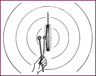 So, to produce sound,
we must produce vibrations. How do we achieve this in the case of the modern electric
horn?
So, to produce sound,
we must produce vibrations. How do we achieve this in the case of the modern electric
horn?
Figure 60. The effect of striking a
gong.
The Diaphragm
In all Lucas horns, the rapid movement of a
thin metal sheet or diaphragm disturbs the surrounding air, setting up sound
waves which travel outwards in much the same way as they did from the gong.
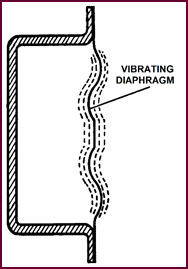
Figure 61. Schematic of a diaphragm
setting up sound waves, the basic element of how an electric horn works.
The rate of vibration of the diaphragm will
determine the pitch and frequency of the note, whilst its loudness or volume
will depend upon the amount of movement of the diaphragm.
Electro-Magnetic Attraction Of The Diaphragm
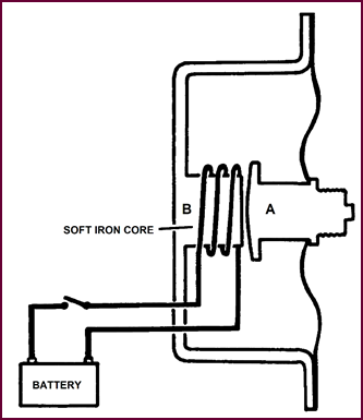 Here you see the same diaphragm, now carrying at its
centre an armature 'A'. At 'B', we have added a coil of wire, wound on a
soft-iron core. This forms an electro-magnet which, if energised by current
from a battery, will attract the armature, bringing with it the central area of
the diaphragm.
Here you see the same diaphragm, now carrying at its
centre an armature 'A'. At 'B', we have added a coil of wire, wound on a
soft-iron core. This forms an electro-magnet which, if energised by current
from a battery, will attract the armature, bringing with it the central area of
the diaphragm.
Figure 62. Illustrating how
electro-magnetic attraction of the diaphragm occurs.
The movement will continue until the
armature strikes the core-face, unless it is restricted by the degree of
flexibility of the diaphragm.
If the current in the coil were suddenly
interrupted, causing the collapse of the magnetic field, the armature would be
released.
Due to its own springiness, the diaphragm
would return after a series of vibrations to its original position.
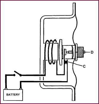 Contact Arrangement
Figure 63. The arrangement of the
contacts.
In practice the current is interrupted by a
set of contacts 'C' which are automatically opened as the diaphragm is
attracted towards the core face. The point at which this happens is determined
by the adjustable screw 'D'.
The pull of the electro-magnet collapses,
releasing the diaphragm. As the latter returns towards its original . position,
the contacts will again close, re-energising the core, and once again
attracting the diaphragm: thus the latter is kept in motion by a series of
impulses, as long as the current supply is maintained.
This is the principle underlying all types
of Lucas horns.
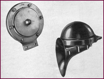 Two Main Groups Of Horns
Figure 64. At left a high frequency horn
and, at right, the well-known Windtone horn.
There are two main groups of horn, the high
frequency type, shown on the left of the picture, and the 'Windtone', shown on
the right. These will be familiar to you all, and we shall describe each in detail.
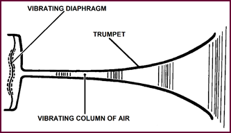
The H.F. Horn
The high-frequency horn gives a relatively
high-pitched and penetrating note. Its method of operation will be clear from
the diagram (Figure 65).
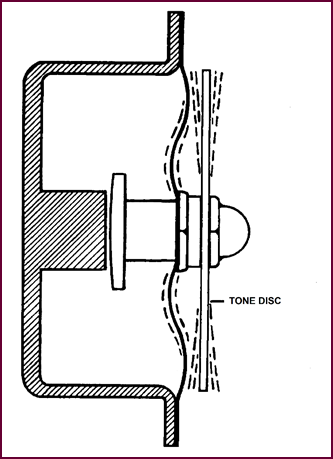 The armature is coupled to the flexible diaphragm which
vibrates as we saw in our previous picture. The rate of vibration is relatively
low, being in the region of 300 to 400 times per second. Attached to the centre
of the diaphr-agm is a tone disc. Each impact of the armature on the core face
is transferred to the centre of the disc, causing the free outer edges to
vibrate at a faster rate. The rate or frequency is determined by the size,
rigidity and material of the disc.
The armature is coupled to the flexible diaphragm which
vibrates as we saw in our previous picture. The rate of vibration is relatively
low, being in the region of 300 to 400 times per second. Attached to the centre
of the diaphr-agm is a tone disc. Each impact of the armature on the core face
is transferred to the centre of the disc, causing the free outer edges to
vibrate at a faster rate. The rate or frequency is determined by the size,
rigidity and material of the disc.
Figure 65. Diagram showing the action of
the tone disc.
The vibrations of the diaphragm and those
of the tone disc blend together, giving the horn its characteristic note.
Three Basic
Types Of H.F. Horn
In Figure 66, we show the three
basic types of high frequency horn: on the left, the HF.1441, in the centre the
HF.1235, and on the right, the HF.1748. All of these work on the principle we
have just discussed, but vary in construction to cater for all specialised
demands.
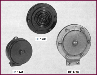 We shall describe the
main features of each of them in turn.
We shall describe the
main features of each of them in turn.
Figure 66. The three basic types of high
frequency horns.
The Light
Weight Horn: H.F.1440-1441-1444
This type of horn has been fitted for
several years to motor cycles, three variations of the basic model being
marketed, the HF.1440, 1441 and 1444. The differences are slight and external,
and in no way affect the operation. Any adjustments we give later will apply
equally well to all three models.
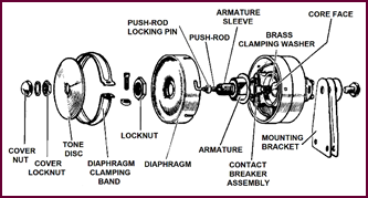 The general construction of the unit is visible in Figure
67. The features already discussed as being part and parcel of every H.F.
horn are readily recognisable. The diaphragm for instance, although slightly
different in shape from the theoretical one we depicted, performs exactly the
same function. It is positioned in this horn by a bayonet fixing. The clamping
band on the left locks this diaphragm firmly in position.
The general construction of the unit is visible in Figure
67. The features already discussed as being part and parcel of every H.F.
horn are readily recognisable. The diaphragm for instance, although slightly
different in shape from the theoretical one we depicted, performs exactly the
same function. It is positioned in this horn by a bayonet fixing. The clamping
band on the left locks this diaphragm firmly in position.
Figure 67. Construction of HF.1440, 1441
and 1444.
The tone disc used with this horn is not
fluted in any way, as is the case with some other models, and is relatively
rigid, the actual thickness of the metal being approxim-ately ⅛" (3·2 m). We have already mentioned
how the shape, flexibility and thickness of this disc determine the final pitch
of the horn note. In addition, we must consider, of course, the mounting
position. As this particular horn is primarily designed for motor cycle work,
it must stand up to rather rougher treatment than that to which it would be
exposed under the car bonnet; a flimsy tone disc on such a horn would scarcely
fill the bill, would it ?
This horn, then, is generally robust in
construction. The mounting bracket, too, consists of a strong yet flexible
assembly of springy plates, which give a firm fixing, capable of withstanding
any amount of engine or road vibration. Horn mountings really have to be good,
other-wise the note will be seriously affected – but we won't labour this point
here: it will be dealt with more fully when we come to 'Maintenance'.
 The armature is also visible here in one of its forms
and so is the core face. The function of the rest of the components, including
the push rod with its locking ring, the contact breaker assembly and the
various locking nuts will be more easily understood when we are dis-cussing the
adjustment of the contact gap.
The armature is also visible here in one of its forms
and so is the core face. The function of the rest of the components, including
the push rod with its locking ring, the contact breaker assembly and the
various locking nuts will be more easily understood when we are dis-cussing the
adjustment of the contact gap.
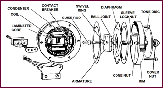
The Altette H.F.1234-1235
 This horn, generally known as the 'Altette' is similar
to the previous one, but of heavier construction. This diaphragm is clamped to
the cast metal body by means of a securing rim held by set-screws. This rim is
chromium plated on the model HF. 1234, whilst that on the H.F.1235 is black
finished. Early models of this horn had a flat aluminium tone disc, and a similar
armature and contact arrange-ment to the HF.1440 type.
This horn, generally known as the 'Altette' is similar
to the previous one, but of heavier construction. This diaphragm is clamped to
the cast metal body by means of a securing rim held by set-screws. This rim is
chromium plated on the model HF. 1234, whilst that on the H.F.1235 is black
finished. Early models of this horn had a flat aluminium tone disc, and a similar
armature and contact arrange-ment to the HF.1440 type.
Figure 68. Construction of the Altette
horn.
 Recently, however, the construction has been modified
somewhat and the latest type is shown in Figure 68. The tone disc is now
of corrugated pressed steel, whilst the earlier type adjustment screw has been replaced
as you can see by a push rod. Provision for adjustment of the contact breaker
is made at the rear of the horn body – but more about this later in the 'Maintenance'
Section.
Recently, however, the construction has been modified
somewhat and the latest type is shown in Figure 68. The tone disc is now
of corrugated pressed steel, whilst the earlier type adjustment screw has been replaced
as you can see by a push rod. Provision for adjustment of the contact breaker
is made at the rear of the horn body – but more about this later in the 'Maintenance'
Section.
The HF.1746,
1747, 1748 Horns
Again, several models of the basic type are
made, cater-ing for individual requirements, but this break-down is generally
applicable to them all.
This horn is a
high performance H.F. horn made in both high and low
note models, suitable for fitting in matched pairs.
It is designed to give an extremely
powerful, arresting and penetrating note which will be audible even under
contin-ental traffic conditions. The construction is very robust and the
adjustment will remain constant over a wide voltage range, a particularly
important characteristic of this type of horn.
Whilst the principle of operation is
similar to the other HF. horns, the construction is very different. This horn
is of a completely new design, having a die-cast body with a laminated core and
armature. Special provision is made for the internal alignment of the armature
with the core face, which explains the presence of such additional com-ponents
as the swivel ring, ball joint, guide rod and core nut. These parts are
machined to very fine limits to permit an extremely accurate adjustment, which
is carried out on the production line and normally needs no resetting in service.
As with the other types of horn, all we shall consider in the way of adjustment
is the contact setting as far as normal servicing is concerned.
Figure 69. Construction of HF.1746, 1748
horns.
You will notice that a condenser is fitted
in this particular horn: it is connected across the contacts to prevent ex-cessive
sparking when the horn is operating.
Windtone Horn –
Principle Of Operation
The 'Windtone' which is the other main type
of Lucas horn, works on rather a different principle from the HF. type. The air
is still set in motion by the electrically-produced vibrations of a diaphragm,
seen here on the left of Figure 70, but this is now attached to one end
of a trumpet. The vibrations will travel up the tube of the trumpet and, if
their frequency is made to resonate with that of the tube, the sound will swell
out and produce a musical note. In simple terms, the length of tube deter-mines
the pitch of the note, and its shape, the overtones or quality. You will
realise then, that in principle the Windtone horn is similar to an orchestral
wind instrument, but with the air vibrations produced electromagnetically
instead of by the mouth and lips.
Figure 70. The principle of the Windtone
horn.
Operation Of
The Windtone Horn
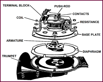 This breakdown of a typical Windtone, Figure 71,
will help us to describe its operation. The actual build-up should be clear
from the illustration. Two die-castings form the trumpet of the horn, at the
same time providing a suitable platform for mounting the diaphragm. You can see
that the latter is sandwiched between the trumpet casting and the base-plate which carries the coil, contact set
and terminal block. The whole is bolted together, the six screws firmly
holding the diaphragm at its edges, leaving the centre free to vibrate. Notice
that the armature is attached to the centre of this diaphragm.
This breakdown of a typical Windtone, Figure 71,
will help us to describe its operation. The actual build-up should be clear
from the illustration. Two die-castings form the trumpet of the horn, at the
same time providing a suitable platform for mounting the diaphragm. You can see
that the latter is sandwiched between the trumpet casting and the base-plate which carries the coil, contact set
and terminal block. The whole is bolted together, the six screws firmly
holding the diaphragm at its edges, leaving the centre free to vibrate. Notice
that the armature is attached to the centre of this diaphragm.
Figure 71. Construction of a Windtone
horn.
Imagine that we energise the coil with
battery current which passes via the contacts illustrated. The armature
is immediately pulled into the centre of the coil. At a set point of its
travel, it strikes against the push-rod, thus opening the contacts. The current
interrupted, the arm-ature is released and the diaphragm springs back towards
its original position. The contacts close again, re-energising the core, and the
whole cycle is repeated, the diaphragm being set into vibration.
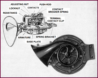 These
electro-magnetically created air disturbances occur at the
orifice of the trumpet; the sound waves travel down the tubing, whose length is
carefully calculated to coin-cide with the frequency of the diaphragm
vibrations. This causes the note to swell out of the trumpet flare.
These
electro-magnetically created air disturbances occur at the
orifice of the trumpet; the sound waves travel down the tubing, whose length is
carefully calculated to coin-cide with the frequency of the diaphragm
vibrations. This causes the note to swell out of the trumpet flare.
The pellet type resistance mounted on the
contact breaker serves to damp excessive sparking which would occur at the
contacts during rapid make and break.
Let us now survey the present day range of
Lucas Wind-tone horns.
Types Of
Windtone Horn
There are three types of Windtone in
general use, the WT.614, the WT.6l6, and the latest addition the WT.6l8.
The WT.614 is an all-black finished horn
for under the bonnet mounting, and is fitted as standard equipment to most
British cars. It is now replaced by the WT.618. The difference between these
two horns are not immediately visible from this photograph and we shall
therefore leave them until we discuss each type individually.
The WT.6l6, perhaps better known as the 'Herald',
is an exceptionally powerful horn mainly designed for overseas use. It is
available in chrome finish for external mounting or in black for fitting under
the bonnet.
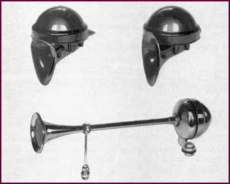 All three horns are supplied in high and low note models
and are primarily designed for use in matched pairs.
All three horns are supplied in high and low note models
and are primarily designed for use in matched pairs.
Figure 72. The three main types of
Windtone horns. Upper left, the WT.614; upper right, the WT.618, and lower
centre WT.616 'Herald'.
The WT.614
The popular WT.614, of which you see two
views here, is small and compact, and gives a note which although clear and
distinctive, the first requisite of any horn, is by no means raucous or
unpleasant. When used in blended pairs, one high note and one low, and operated
simultaneously, WT.6l4 horns give a pleasantly mellow and harmonious signal.
You will notice that the horn trumpet is
coiled so as to obtain the desired length in the minimum of space.
The high note model has the shorter coiled
tube and the letter 'H' is imprinted inside the trumpet flare. The letter 'L'
is used to distinguish the low note version.
Figure 73. The WT.614, here, is small
and compact.
Certain of the smaller cars fit one Windtone
horn only as standard equipment, usually the low note one. The high note model
to make the matched pair is then available as an optional extra.
As a point of interest to the musicians
among you, the notes differ in pitch by the interval of a major third.
The fixing bracket of the horn is of
interest and of consid-erable importance: it must be firm, yet at the same time
flexible. The one used here is a spring bracket formed from two sections.
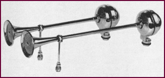 The remainder of the constructional details of this horn
are shown in Figure 71 – we actually used the WT.614 as a general
example. But the accompanying illustration shows the relative positions of the components
when assembled. A feature not previously pointed out is the adjusting nut for
setting the contacts. The significance of this will be further discussed in the
'Maintenance' section of this book.
The remainder of the constructional details of this horn
are shown in Figure 71 – we actually used the WT.614 as a general
example. But the accompanying illustration shows the relative positions of the components
when assembled. A feature not previously pointed out is the adjusting nut for
setting the contacts. The significance of this will be further discussed in the
'Maintenance' section of this book.
The WT.6I8
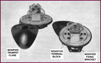 These new WT.618 horns, very similar in general appearance
to the WT.614 model we have just shown you, have been designed to supersede the
latter. They have a much louder note and will give a much more audible warning
signal under heavy traffic conditions. They are intended for use in matched pairs
and will normally be fitted under the bonnet. As usual, both 6-volt and 12-volt
models are produced.
These new WT.618 horns, very similar in general appearance
to the WT.614 model we have just shown you, have been designed to supersede the
latter. They have a much louder note and will give a much more audible warning
signal under heavy traffic conditions. They are intended for use in matched pairs
and will normally be fitted under the bonnet. As usual, both 6-volt and 12-volt
models are produced.
Figure 74. The new Lucas WT.618 Windtone
horn.
The external modifications are not
immediately obvious: the trumpet flare has actually been re-designed and the
coiling of the trumpet tube somewhat altered. This slightly changes the
characteristic of the low note.
The bottom picture shows the modified
spring-steel fixing bracket.
The main internal modification concerns the
contact breaker assembly. The terminal block is now made of resistive material
which does away with the earlier pellet type resistance used in the WT.6l4.
The diaphragm too has slightly different
characteristics.
The Herald Horn
The Herald horn, the largest and loudest of
the Lucas range, fits a movement which looks identical to the WT.614, having
the same coil and contact breaker arrangement, with a points resistance in circuit.
Here the similarity ends. The Herald has a very dignified-looking, chromium
plated trumpet, something like the old post-horn. Blended pairs are produced,
the longer trumpet giving the low note. These large horns are designed for
external mounting on the larger cars and long distance coaches, although a
similar model finished in black is available for interior fitting.
Figure 75. A pair of the WT 616 Herald
horns.
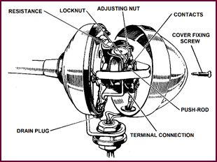 WT.616 Mechanism
Figure 76. The WT.616 mechanism.
Here you see the WT.6l6 with the cover
removed. The similarity between this
mechanism and that of the WT.614 is evident. The only additional feature
we need point out is the drain plug. This is provided so that the horn can be
drained if for any reason the interior becomes filled with water – as may happen,
for instance, during the hosing down of the car.
The WT.616 Trumpet
Support
The long
trumpet of the Herald naturally needs supporting and here you see the type of
chromium plated pillar we supply.
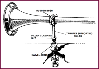 The pillar itself is extendable and possesses a
swivel point, enabling the fixing position to be varied sufficiently to suit
the contours of the car wing or bonnet, etc. This mounting facilitates fitting
and avoids any strain on the trumpet.
The pillar itself is extendable and possesses a
swivel point, enabling the fixing position to be varied sufficiently to suit
the contours of the car wing or bonnet, etc. This mounting facilitates fitting
and avoids any strain on the trumpet.
Figure 77. The WT.616 trumpet support
assembly.
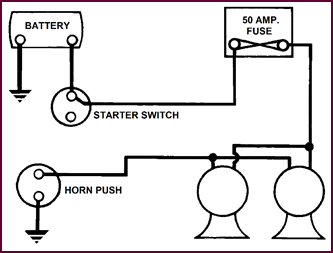 You will notice that the trumpet clamp is rubber bushed
against vibration.
You will notice that the trumpet clamp is rubber bushed
against vibration.
We shall now discuss how the horns we have shown
you are wired into the vehicle electrical circuit.
H.F. Horn
Circuit
 Figure 78 shows a
typical circuit used for a single H.F. horn, say of the 'Altette' type. You will
notice that the horn obtains its current feed from the A2 terminal – which as
you know may be situated on a separate fuse board, or else incorporated in the
control box. In either case the circuit is protected by the 35 ampéres A1 to A2 fuse.
Figure 78 shows a
typical circuit used for a single H.F. horn, say of the 'Altette' type. You will
notice that the horn obtains its current feed from the A2 terminal – which as
you know may be situated on a separate fuse board, or else incorporated in the
control box. In either case the circuit is protected by the 35 ampéres A1 to A2 fuse.
Figure 78. H.F. horn circuit diagram.
The horn operating push is usually in the
earth line as we have drawn it here.
There is no rigidly set supply point for a
horn of this type, it could equally well be fed direct from the battery or from
the battery side of the ammeter. The A2 terminal is, how-ever, generally the
most convenient point. The voltage drop occurring at intermediate points in the
circuit bet-ween the battery and this terminal is normally negligible with a
horn of this type whose current consumption is relatively low. Where two H.F.
horns are used, on the other hand, we advise that they should be fed either
from the battery terminal itself, or from the battery side of the starter
switch or ammeter. In this case, it would also be preferable to install a
separate 35 ampére fuse in the
circuit.
Windtone Horn
Circuit
Windtone horns take much heavier currents
than the H.F. type and it is normal practice to feed them direct from the
battery line, either from the battery terminal, or as we show here from the
battery side of the starter switch.
A separate 50 ampére fuse is recommended, though this precaution is not always taken.
The horn push is once again in the earth
line.
This circuit is adequate for all cars where
the cable run is not too long, especially when two 12-volt horns are in-stalled.
The voltage drop on the circuit in this case would be well within working limits.
A serious voltage drop is soon noticeable, the horn note becomes rough and the
power diminishes, although the pitch of the note will remain more or less the
same.
Figure 79. Windtone horn circuit diagram
Where such a heavy voltage drop would be
experienced – say on some of the larger cars or light commercials, and
especially when a pair of 6-volt horns is used – a relay should be employed in
the circuit.
We show this arrangement in Figure 80. (Page
29)
Typical Horn
Circuit With Relay
Here you see a typical relay circuit, such
as would be employed for the heavier current horns – the 6-volt Wind-tone, the
' Herald' models, etc.
The relay possesses three terminals: 'C1', 'W'
and 'C2'. The main supply cable from the battery is connected via a fuse
to 'C2'. Terminal 'W' is joined by a cable passing up the steering column to
the horn push. The other horn-contact is earthed.
When the horn push is pressed, the
operating circuit for the relay is completed and battery current passes round
the windings, energising the core, and thus closing the relay contacts. These
contacts complete the horn oper-ating circuit, allowing the main current to
pass from the battery via terminal 'C2' ,through the relay contacts,
then via 'C1' on to the horns. The circuit is completed by means of the
horn and battery earths.
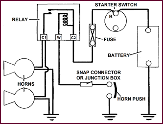 This relay arrangement relieves the horn push, and
the usual long run of wiring to it, of carrying the main current taken by the
horns. Two purposes are thus served: the horn push contacts have a much longer
life, and any volt-age loss which would occur if the heavy horn operating
current passed through the low capacity column wiring has been avoided. The horns
therefore receive their full voltage. What is more, the main circuit wiring can
now be of any reasonable length as heavier gauge cable will normally be used,
the steering column which limits the cable size having been by-passed.
This relay arrangement relieves the horn push, and
the usual long run of wiring to it, of carrying the main current taken by the
horns. Two purposes are thus served: the horn push contacts have a much longer
life, and any volt-age loss which would occur if the heavy horn operating
current passed through the low capacity column wiring has been avoided. The horns
therefore receive their full voltage. What is more, the main circuit wiring can
now be of any reasonable length as heavier gauge cable will normally be used,
the steering column which limits the cable size having been by-passed.
Figure 80. Horn circuit with relay.
This almost concludes what we have to say
on the subject of horn circuits. You will have gathered that there is no hard
and fast rule as to the precise method of connecting horns in circuit. The main
recommendations we make are that they must be installed so that the volt-age
drop is absolutely at a minimum. The governing factor in this respect is the current
consumption of the horn: the heavier the current, the greater will be the pos-sibility
of power losses. Very much part of this problem is the cabling itself. Certain
sections of the horn circuit must of necessity be wired in cable of a low
current carrying capacity; the lead inside the steering column for instance is
normally part of a relatively narrow gauge multi-cored cable – no amount of
persuasion can introduce a size 44/·012 cable where there is only room for a 14/·012.
Hence you have seen that where a pair of heavy current Windtone horns is used
we employ a relay in the circuit which by-passes the column wiring and horn
push, thus avoiding voltage losses. The only current carried by this section of the circuit is that necessary to
operate the relay, a mere 0·5 amps. for the 12-volt set and 1·5 amps.
for the 6-volt. The main operating current, in the order of 13 amps. for the 12-volt
pair and 26 amps for the 6-volt takes the direct path from battery to horn,
passing through a section of the circuit where it is convenient to install
heavier cabling capable of carrying such currents without undue loss.
Another recommendation is that the horn
should be fused. You saw that in the case of a simple H.F. horn, taking a low
current, we used the existing A2 fuse. But where two similar horns are fitted,
we recommended that they should be fed from a point nearer to the battery, with
a separate fuse in circuit. The Windtone horns as well should not be fed from the
A2 fuse; if they are, the car ammeter in circuit will swing violently every
time the horn button is pressed.
The above considerations then should be
borne in mind when studying these horn circuits, and more particularly if you
are called upon to fit new or additional horns to an existing installation.
Let us now see what maintenance and
servicing is neces-sary to keep horns in
good working condition on the vehicle.
Maintenance
Points
There are very few maintenance points which
apply to horns – but the few are extremely important.
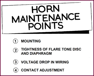 Each horn is correctly
adjusted before it leaves the factory and will generally give long and
satisfactory service with the minimum of attention.
Each horn is correctly
adjusted before it leaves the factory and will generally give long and
satisfactory service with the minimum of attention.
Figure 81. Maintenance topics for horns.
Here you see four maintenance points, it is
our exper-ience that by checking these you will cure most of the horn troubles
that occur, without the need for removing and stripping the units, so often
done unnecessarily.
Let us take each in turn, starting after
the normal fashion with point No. 1.
Horn Mounting
Horns must always be mounted on the bracket
provided, and it is important that this bracket is securely bolted to a rigid
part of the vehicle, one that is free from vibration. Make sure too that the
horn body is not touching any-thing. Unless the horn is securely mounted, it
will not give its true, clear note.
If at any time imperfections in the horn
note become apparent, check that the fixing bolts are correctly tight-ened,
that the bracket is not cracked and that no other 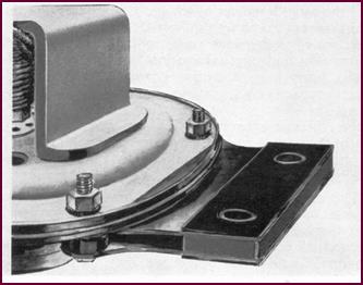 unit is loose and vibrating in the immediate
vicinity.
unit is loose and vibrating in the immediate
vicinity.
Figure 82. An example of a horn's
mounting assembly.
Loose Horn
Components
If any part of the horn itself is loose,
such as the cover, the diaphragm, the tone disc, horn flare or grille, etc.,
the horn note will be affected.
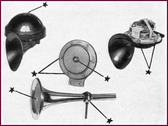 We have indicated all the likely trouble spots, with
stars, in this picture.
We have indicated all the likely trouble spots, with
stars, in this picture.
Figure 83. Typical loose horn
components.
Voltage-Drop
Tests For Horn Circuit
We have stressed throughout that the horn
performance will be seriously affected by voltage losses in the circuit.
To localise this fairly common cause of
trouble a four-stage voltage-drop test may be simply applied.
TEST 1. Battery
voltage underload – engine stopped.
Switch on all lights to load the battery.
Take a battery voltage reading, which
should not be less than 11-volts if the
battery is in an adequate state of charge.
TEST 2. Repeat
this operation at the horns.
Connect the voltmeter across the terminals
of each horn in turn, press the horn push and note the reading. The voltage
registered should be no more than 0·5 volts below the Test 1 reading.
TEST 3. If
voltage drop is in excess of 0·5-volt.
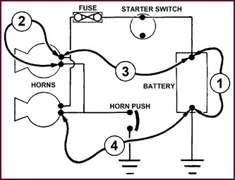 Check the insulated line by connecting the meter bet-ween
the insulated battery terminal and the feed terminal of one horn. Press the
horn push. No voltage reading should be obtained; if there is, check all cable
connect-ions and junction points in the feed line for loose or dirty contacts.
Check the insulated line by connecting the meter bet-ween
the insulated battery terminal and the feed terminal of one horn. Press the
horn push. No voltage reading should be obtained; if there is, check all cable
connect-ions and junction points in the feed line for loose or dirty contacts.
Figure 84. Voltage-drop tests for horn
circuit.
TEST 4. Voltage
drop due to defective earth.
The final test (Test 4) will locate any
voltage loss due to a bad earth contact. The meter is connected between the
battery earth terminal and the horn earth terminal (i.e., terminal connected to
horn push), when full battery should register. On operating the horns the
voltage read-ing should drop to zero – or 0·5-volt is considered as the
permissible maximum.
All earth connections should be examined if
a reading in excess of this value is obtained.
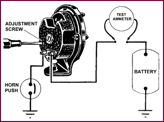 Horn Contact Adjustment
Figure 85. Horn contact adjustment.
The only adjustment to the horns normally
necessary in service is the taking up of the contact wear.
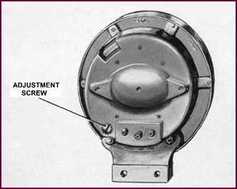 After a lengthy period of service, the horn note tends
to deteriorate slightly, both in volume and in purity of tone. The cure is
simple enough: every horn is provided with an adjustor which compensates the normal
service wear. The actual positioning of this adjustment varies with each type
of horn and we shall need to run through them in turn. One point is common to
all, the contact adjustment MUST be made with an ammeter in circuit as we show
here. The contacts should be adjusted until the specified current reading is
obtained.
After a lengthy period of service, the horn note tends
to deteriorate slightly, both in volume and in purity of tone. The cure is
simple enough: every horn is provided with an adjustor which compensates the normal
service wear. The actual positioning of this adjustment varies with each type
of horn and we shall need to run through them in turn. One point is common to
all, the contact adjustment MUST be made with an ammeter in circuit as we show
here. The contacts should be adjusted until the specified current reading is
obtained.
We shall state the specified value for
individual horns, and the figure quoted will be at normal battery voltage. This
pre-supposes that the vehicle engine is stationary and the battery well charged.
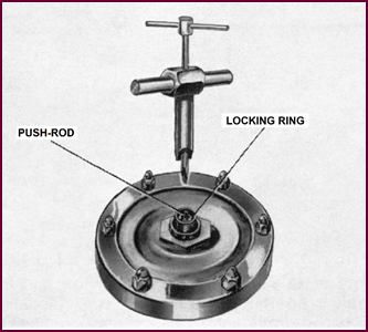 Contact Adjustment: The HF.1441
Type
Contact Adjustment: The HF.1441
Type
Figure 86. Contact adjustment on
HYF.1441 model.
The HF.1441 type, and earlier models of the
HF.1234 models have no fine adjustment screw at the back of the horn. To gain
access to the adjustment, the cover nut must first be removed. Using a combined
tool similar to the one illustrated here, which holds the locking ring while
the push rod is adjusted, the slotted end of the rod may be turned until the
following readings are obtained on the ammeter in circuit (?when horn is
operated?):
6-volt model 3 amps.
12-volt model 2 amps.
These are average figures and slight
variations may be encountered.
If the consumption is excessive, turn the
push rod clock-wise to decrease the current,
or anti-clockwise to increase. Make only a small adjustment at a time, continuing
until the correct setting is obtained.
Contact
Adjustment:
The HF.1234, 35
And HF.1746, 1748
These horns have a fine adjustment screw at
the back of the body. With an ammeter in circuit, note the current when the
horn is operated. Turn the screw in a clock-wise direction to increase the
current and anti-clockwise to reduce it. Adjust a quarter of a turn at a time
until the reading is within the following prescribed limits and the maximum
performance is obtained. Current figures:
|
|
6-volt
|
12-volt
|
|
HF.1234–35
|
3·5 amps. Max.
|
2·5 amps. Max.
|
|
HF.1746, 47, 48
|
5 amps. Max.
|
4 amps. Max.
|
Figure 87.
Contact adjustment models HF.1234, 35 and HF.1746, 1748.
Contact
Adjustment WT.614, 616 and 618
 The following method of adjustment applies to all the
present-day Windtone horns we have discussed.
The following method of adjustment applies to all the
present-day Windtone horns we have discussed.
Figure 88. Contact adjustment, Windtone
horns.
First remove the cover. Then slacken the
lock nut on the fixed contact and turn the adjusting nut in a clock-wise
direction until the contacts are just separated, as indic-ated by the horn
failing to sound. Turn the adjusting nut half a turn in the opposite direction and
hold it while tightening the locking nut. Check the current consumption of the
horn, which must not exceed the figure quoted below. If the current is incorrect,
make further very fine adjustments to the fixed contact, turning the adjusting
nut clock-wise to decrease and anti-clockwise to increase.
Current figures:
|
|
6-volt
|
12-volt
|
|
WT.614
|
13 amps.
|
6 amps.
|
|
WT.616
|
14 amps.
|
8 amps.
|
|
WT.618
|
N/A
|
8 amps.
|
PART THREE:
TRAFFICATOR: SEMAPHORE DIRECT-ION INDICATORS
The Current Production Semaphore Indicator
On current production cars TWO basic types
of Traffic-ators, the SF80 and SE100, cover
all the popular vehicles. Two other types known as the SF34 and 40, and
now discontinued on new cars, have also been used in large numbers. These
models are fitted on the vehicle assembly lines and are generally accommodated
in recessed door pillars. For subsequent installation an external mounting
unit, the SE100, is universally applic-able. The same action assembly is used
either for the recessed type or the box type external trafficator. The methods
of switching vary, the most popular being the self-cancelling switch built in
the steering-wheel hub. Another arrangement uses
a self-cancelling switch mounted on the steering column and cancelled by
an external cam.
A further arrangement may be a panel
mounting, two-way and off switch with or without a warning light or altern-atively
a two-way and off switch combining a pneumatic time delay. Generally these units
are for 12-volt working but are also available for 6-volt applications with a
special 24-volt model for passenger carrying vehicles.
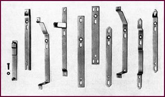 Mounting Plates
Figure 89. A selection of trafficator
mounting plates.
For mounting on different types of vehicle
bodies a range of adaptor plates are manufactured. These are attachable to the
standard action assemblies and some examples are grouped together in Figure 89.
Principle Of
Operation
All types of trafficators follow the same
principle. A solen-oid is carried on a bracket and a plunger is attached to the pivoted semaphore arm. When current passes
through the solenoid winding the plunger is drawn into the core thus
raising the arm to the horizontal position where it will remain until the
current is switched off.
A signal light in the form of a 3 Watt
Festoon type bulb is spring supported in the moulded arm and switched on by
means of a sliding contact adjacent to the pivot part of the arm when the arm
itself rises to the horizontal. Some earlier
models had a continuous flexible lead to this signal.
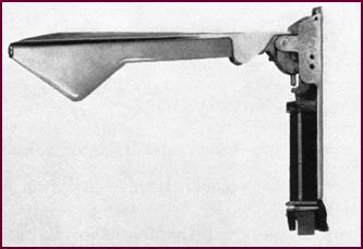 All current production models which are made for
both 6 and 12-volt working have a 7¼" (184 mm) arm.
All current production models which are made for
both 6 and 12-volt working have a 7¼" (184 mm) arm.
Figure 90. A model SF80 in horizontal position.
The indicator arm should return to the 'at
rest' position by its own weight when the current is switched off. Wind
pressure against the arm surface tends to keep it in the raised position and the
top surface is given an aero-dynamic contour whereby a downward thrust is
produced to return the arm.
To prevent the arm being raised or 'thrown
up', when not in use, a locking device is incorporated. Unless the plunger
itself is moved, some force must be exerted upon the arm before the action of
this device is overcome.
The Solenoid
Action
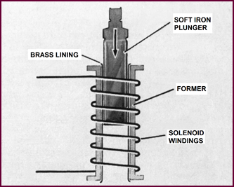 Figure 91, illustrates the solenoid with its
hollow iron centre, around which is a winding of enamel covered wire.
Figure 91, illustrates the solenoid with its
hollow iron centre, around which is a winding of enamel covered wire.
Figure 91. Cross section of trafficator
solenoid.
A characteristic of this kind of
electro-magnet is that, with the current switched on, its pulling power is at
maximum when the armature is fully inserted in the core and advan-tage is taken
of this characteristic because the pull required increases as the arm is raised
from the vertical towards the horizontal position.
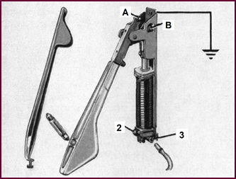 It may be observed that
the hollow core of the solenoid has a brass lining, the object of which is to prevent
'Magnetic cling' between the surface of the plunger and
the wall of the core.
It may be observed that
the hollow core of the solenoid has a brass lining, the object of which is to prevent
'Magnetic cling' between the surface of the plunger and
the wall of the core.
The current required to operate the
solenoid lies between 2 and 3 ampéres.
Self-Locking
Device
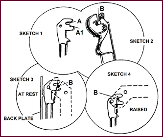 A self-locking device to hold the arm in the 'at rest'
pos-ition is an essential feature of the arrangement to prevent the arm from
bouncing out when the vehicle is swaying, bumping or heeling over at an acute angle.
Several devices have been applied at various times and this set of sketches
shows the very simple arrangement provided on current production trafficators.
A self-locking device to hold the arm in the 'at rest'
pos-ition is an essential feature of the arrangement to prevent the arm from
bouncing out when the vehicle is swaying, bumping or heeling over at an acute angle.
Several devices have been applied at various times and this set of sketches
shows the very simple arrangement provided on current production trafficators.
Figure 92. Trafficator arm, self-locking
device.
The locking device operates in the
following manner:
Sketch 1. The flattened head of the plunger is recessed to accommodate a
catch pin in the positions shown at 'A' when the arm is raised and 'A1'
when the arm is down.
Sketch 2. The plunger head fits into the slotted top of the signal arm and a
catch pin 'B' is located in the recess shown and retained by means of a
hairpin spring.
Sketch 3. With the signal arm in the 'at rest' position, the solenoid plunger
is fully raised and the catch pin 'B' will be in the position shown. The
plunger head then forms a block between the back plate and the pivoted arm
which prevents the arm from moving outwards.
Sketch 4. When the plunger is drawn down into the solenoid, the first part of
the movement releases the lock and the continued downward movement of the plunger
raises the arm into the horizontal position; the catch pin will then be in the
position shown.
Referring to Sketch 2, the location
of the catch pin 'B' by means of the hairpin spring also acts as a safety
device, allowing the pin to rise in the recess when the arm is forced up by
hand, thus preventing it becoming damaged.
SF80 Trafficators
Figure 93
shows the current production SF80 type trafficator made for both 6 and 12-volt working,
now being fitted to practically all vehicles taking trafficators as initial
equipment.
Figure 93. Model SF80 Trafficator.
This is an exceptionally compact unit and
is very narrow ¾" (19 mm) and shallow 1½" (38 mm) thus enabling it to
be accommodated conveniently in restricted door pillars.
Another development is the quickly
removable arm ass-embly, which permits a broken arm to be replaced in a few
moments without taking out the assembly from the door pillar.
From Figure 93, the following
features should be noted:
1. The button contact 'A' for the signal light which connects
with the blade 'B' when the arm is raised.
2. The rubber buffer stop '2' which supports the arm in the
down position and prevents rattle.
3. A thimble type of connector '3' for the current supply at
the bottom.
4. The earth return obtained
through the mounting plate and the body of the vehicle.
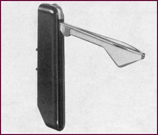 SE100 Trafficator For
External Mounting
SE100 Trafficator For
External Mounting
Figure 94. SE100 trafficator for
external mounting.
For external mounting the SF80 movement
which we have just described is accommodated in a metal box as shown here.
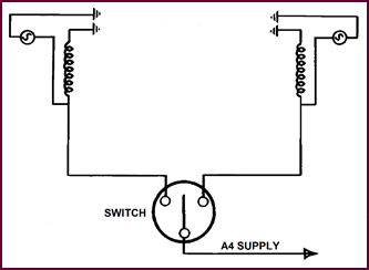 Two holes in the back plate allow the assembly to be
fast-ened directly on to a flat surface and a detachable right angle bracket will accommodate side fixing where
required.
Two holes in the back plate allow the assembly to be
fast-ened directly on to a flat surface and a detachable right angle bracket will accommodate side fixing where
required.
The unit is available for both 6 and 12-volt
working. It has an exceptionally wide field of application for vans and
commercial vehicles as an after-sales fitment.
SF34 And SF40 Trafficators
Prior to the introduction of the SF80, the
two most popular trafficators in use were the SF34 and SF40 as illustrated in Figure
95.
The feature of the SF 34 Trafficator was
its particularly narrow construction; it was also made with both 7¼" and 8¼"
arm.
 The leading feature of the SF40 was its extreme shallow-ness
from back to front.
The leading feature of the SF40 was its extreme shallow-ness
from back to front.
Figure 95. Left, model SF34 and, right,
model SF40.
Several models
of these trafficators were made with various angles of lift between 80° and 90°
and others with special contacts for panel warning-light circuit arrangements.
Wiring Circuit
Used On Current Production Equipment
Numerous circuit arrangements have been installed
on earlier production cars to meet special requirements and at a later stage
they will be included as a matter of general interest.
An extremely simple circuit is now employed
for the SF80 and SE100 trafficators as shown in Figure ??.
The current supply is taken from the A4
fuse by means of a GREEN cable 14/012 to the centre contact of the switch,
usually via snap connector at the bottom of the steering column
assembly.
GREEN and WHITE and GREEN and RED 14/012
cables are then connected, also by means of snap con-nectors, to each
trafficator.
As shown in the diagram, it will be
observed that the solenoid is connected directly to earth and the signal light
forms a parallel circuit to it.
As previously mentioned, the earth return
is through the frame of the trafficator to the body of the vehicle and, unless
these earth connections are sound, considerable trouble may be experienced in
service.
Figure 96.
Wiring circuit diagram used in current production.
Servicing
Trafficators: Arm Replacement
In order to renew a broken arm on any of
the early type trafficators it was necessary amongst other operations, to drill
out the hinge pin. On the SF80 and SE100 models the new type,
quickly-detachable arm is used.
The left-hand illustration shows how the
exchange may be carried out:
OP. 1. Remove the screw and take off the arm
OP. 2. Lift out the bulb and its contact spring.
OP. 3. Loosen off the arm clamping screw and with-draw the arm
moulding.
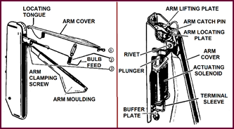 Reverse the operations and fit a new arm moulding.
Figure 97. Method of trafficator arm
replacement.
On the earlier types shown on the right
proceed as follows:
Remove the trafficator from the car, take
off the arm cover and remove the bulb. If the old cable and contacts are to be
used, open the clip securing the cable to the arm; otherwise slacken the screw securing
the terminal as-sembly, remove the terminal plate and un-solder the cable,
temporarily replacing the screw to hold the solenoid in position.
Drill out the rivet securing the arm.
Place the new arm in position so that the
catch pin locates correctly between the lifting plate and the locking plate,
and secure by fitting a new rivet. Solder the free end of the braided cable to
the tag on the terminal plate, and refit the plate in position. Before finally
tightening the securing screw, fit the cable neatly between the coil and the
insulating strip, so that, although held firmly, there is no danger of the insulation
being damaged by sharp edges. There must be sufficient slack to allow the arm
to move freely without either straining the cable or bending it sharply.
Finally, fit the bulb into the arm and
replace the cover.
Lubrication And
Maintenance
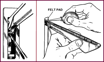 SF80 and SE100. The
only lubrication required on these trafficators is one drop of S.A.E. 30 oil on
the pivot-bearing of the arm occasionally.
SF80 and SE100. The
only lubrication required on these trafficators is one drop of S.A.E. 30 oil on
the pivot-bearing of the arm occasionally.
Figure 98. Lubricating the trafficator.
SF34 and
SF40. There are two
lubrication points on these trafficators, and both should be lubricated occasionally.
a) Lift the trafficator arm and apply one drop of thin machine oil
to the catch pin between arm and the operating mechanism.
b) Withdraw the screw at the end of the arm and slide off the arm
cover. Move the bulb connecting lead to one side and apply a drop of thin oil
to the felt lub-ricating pad at the top of the arm.
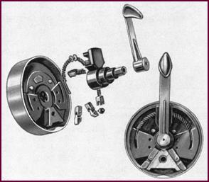 Switching Arrangements
Figure 99. The self-cancelling switch.
A variety of switch arrangements have been developed
and are available to meet the vehicle manufacturers' demands, in particular to
suit the varying types of steering-column controls in general use.
The most popular arrangement on current
production cars is the 'Self-cancelling' switch shown in Figure 99.
The self-cancelling switch assembly, built
into the hub of the steering wheel, is very simple if regarded as com-prising
two elements: an electrical element, the switch itself, and a mechanical
element, being the actuating and self-cancelling device. The operation is that
the current supply is switched on by the hand lever and switched off
automatically when the steering wheel is returned to the straight ahead
position after a turn has been completed.
The right hand illustration in the picture
shows the complete assembly as it rests in the centre of the steering wheel,
that on the left shows an exploded view of the components.
The Self-Cancelling
Switch Assembly:
The Switch Only
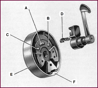 The switch itself is of the standard TWO way type with
a central OFF position. The supply contact is shown at 'A' and the
trafficator contacts at 'B' and 'C'. The rotor to which the hand
lever is connected contains a spring loaded bridging contact 'D'.
Movement of the lever to the left or right connects the respective trafficator;
central-ising the lever switches the current off.
The switch itself is of the standard TWO way type with
a central OFF position. The supply contact is shown at 'A' and the
trafficator contacts at 'B' and 'C'. The rotor to which the hand
lever is connected contains a spring loaded bridging contact 'D'.
Movement of the lever to the left or right connects the respective trafficator;
central-ising the lever switches the current off.
Figure 100. The self-cancelling switch
mechanism.
The switch base, rotor and lever assembly
are mounted on a stator tube and held stationary by a clamp at the bottom of
the steering column.
An outer ring 'E' with a cam 'F'
is turned with the steering wheel and actuates the self-cancelling mechanism.
The
Self-Cancelling Action
Sketch 1. The
Rotor Lever 'I' is centralised by means of the two coil springs 'G'
and is firmly held in this position by the spring loaded Roller 'H', locating
in the notch as shown.
Sketch 2. Movement
of the Rotor Lever – say to the right – switches on the current to the right
hand trafficator and at the same time com-presses the spring 'G' on that
side.
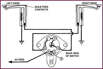
 The Roller 'H' will then be
in the position shown over the pawl 'J' and will hold the switch in this
position.
The Roller 'H' will then be
in the position shown over the pawl 'J' and will hold the switch in this
position.
Figure 101.The self-cancelling operation
described.
Sketch 3. When
the steering wheel is then turned in the same direction – right – the cam 'F'
will override the pawl.
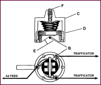 Sketch 4. When the steering wheel is moved
back again to the left to straighten up after the turn has been made, the cam
forces the pawl upwards, pushing the roller into the boss of the rotor lever.
Sketch 4. When the steering wheel is moved
back again to the left to straighten up after the turn has been made, the cam
forces the pawl upwards, pushing the roller into the boss of the rotor lever.
The compressed spring 'G' then returns the
lever to the central position, when the roller 'H' re-engaging with the
notch, positions it in readiness for the next operation.
Typical Arrangement
With Panel Mounting Switch And Warning Light
A popular type of switch for this
arrangement is the type SD84 incorporating a warning light. The circuit arrange-ment
is as shown in Figure 102.
The SD84 two-way and off switch (centre of
diagram) has a group of four main terminals, 2, 3, 4, 5,
of which the centre pair 3 and 4 are permanently linked. These
terminals act as switch contacts and are linked in pairs by a roller on the
switch arm 'A'.
Centre position of the switch is OFF and by
moving the rotor to left or right, terminals 2/3 or 4/5
are linked, thus feeding current to either trafficator.
The Warning Light is connected between
terminals 2 and 5 as shown.
If the switch is moved to link terminals 4
and 5, i.e., the right-hand trafficator, the warning lamp circuit will
then be from terminal 5 through the lamp bulb filament to terminal 2
and from this point its circuit is completed through the Left-hand trafficator to
earth. In this condition the very small current passing through the warning lamp
bulb is not sufficient to cause any movement of the Left-hand trafficator.
Figure 102. Typical circuit diagram with
panel mounted switch and warning light.
If the switch is moved over to link
terminals 2 and 3 to operate the Left-hand trafficator, the
warning lamp circuit will then be completed through the Right-hand trafficator.
The Warning Light is of the screw-in type,
and connected between terminals 2 and 5 as shown.
The Pneumatic
Time Switch
An alternative to the layout we have just
examined is the Pneumatic Time Switch, which will provide a self-cancelling arrangement
for a vehicle not so fitted originally and which, incidentally, avoids the necessity
for a warning light.
Figure 103. The pneumatic trafficator
switch.
The switch itself is a plain TWO WAY-OFF
type as gen-erally used. The complete assembly comprises an air chamber 'C'
with a piston 'D' on the skirt of which are formed cams 'E'
together with a loading spring and an air regulating screw 'F'. The
switch rotor is fitted with a horizontal pin 'B' which registers with
cams 'E' and is normally held in the central or OFF position.
During the return movement of the piston,
the cam face pressing on the pin 'B' turns the switch rotor to its
original central and off position.
Movement of the switch lever to right or
left through about 60° switches on the current supply to the trafficator and at
the same time raises the piston through the rotation of pin 'B' moving
over the cam face 'E', the air from the cylinder escaping around the
sides of the bucket piston. Since all the air has been expelled from the
cylinder, the spring can only return the piston to its original position as air
is allowed to re-enter the cylinder.
An adjustable air leak 'F' is
provided to enable this return movement to be delayed over a period of from 10
to 12 seconds. During the return movement of the piston, the cam face pressing
on the pin 'B' turns the switch rotor to its original central and off
position.
A snap action in finally opening the switch
contacts is obtained by means of a spring loaded ball in the switch rotor
assembly.
Trafficator
Mechanical Troubles
Trafficators occasionally get bent or
damaged in service, resulting in binding or stiffness which will prevent the
trafficator from rising fully or returning to the correct parked position.
If the supply line is in order the
trafficator should be examined to make certain that it is not binding or sticking
through faulty adjustment or lack of lubrication.
It may be necessary to remove a trafficator
from the vehicle to ease or adjust it, in which case it should be tested as
detailed.
The minimum voltage required to lift the
trafficator arm to the horizontal should be measured at the terminals of the
unit and should read as follows:
12-volt unit no
less than 9-volts;
6-volt unit no
less than 4·5 volts.
During the test, the trafficator should be
'tilted
backwards at an angle of 5° to the
vertical. The bulb should also be in circuit.
The arm must return to the locked position
and not rattle when released from any position of making an angle of 60° to the
vertical.
The current taken by the trafficator is:
12-volt models
approximately 3 amps.
6-volt models
approximately 6 amps.
Service Testing
The Trafficator System
Where a
trafficator fails to operate or is sluggish, the fault may not necessarily be
confined to the trafficator movement.
Due to the unavoidably long lengths of
cables and num-erous connections in the circuit, high resistance may be the
cause of considerable voltage loss.
The recommended cable size is 14/012;
voltage loss will occur if a smaller size of cable is used. Trafficators should
operate efficiently down to 9-volts on the 12-volt system and 4·5 volts with 6-volt
system.
A systematic series of checks may be
carried out on the entire circuit to localise a fault.
After switching on the ignition, the
sequence of oper-ations should be as follows:
1. Test the battery.
2. Operating voltage at the battery.
3. Operating voltage at the trafficator.
4. Voltage drop on the insulated line.
5. Voltage drop on the earth line.
TEST 1. The Battery
Test the battery to ensure serviceability
and state of charge; this can most conveniently be carried out by switching on
the Head Lights and taking a voltage reading across the battery terminals.
If the battery is serviceable and in a
reasonable state of charge, apply Test 2.
TEST 2. Operating Voltage At The Battery
Connect the voltmeter between positive and
negative terminals of the battery.
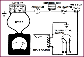 With ignition switched
on, move the indicator switch over to supply the faulty trafficator and note the
voltage reading.
With ignition switched
on, move the indicator switch over to supply the faulty trafficator and note the
voltage reading.
Figure 104. Circuit diagram for Test 2.
TEST 3. Operating Voltage At The
Trafficator
Next connect the voltmeter, as shown for
Test 3 between the insulated terminal and the frame of the trafficator. Check
the voltage-reading.
The difference between this and the
previous reading should not exceed 0·5-volt. Should the difference be greater,
it will indicate high resistance in the circuit.
TEST 4. Testing The Insulated Line
For the next test, connect the voltmeter to
the insulated terminal of the trafficator and the negative battery lug.
When the supply is switched on the reading
should not exceed 0·5-volt: if a higher voltage is registered it will indicate
a high resistance somewhere along the line.
The high resistance can then be traced by
testing across the snap connectors and across the indicator switch contacts.
Where the switch is located at the top of the steering column, the test can
most conveniently be made at the snap connectors, located at the base of the
column. In all tests there should be no reading on the voltmeter.
TEST 5. Voltage Loss On Earth Line
Connect the voltmeter between the frame of
the trafficator and the positive battery lug and with the supply switched on,
there should be no reading on the voltmeter. Any volt-age reading will be due
to high resistance.
One of the most likely causes will be a
defective earth connection for the trafficator. Check by connecting the
voltmeter between the trafficator frame and in close proximity to the earth
connection.
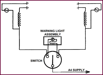
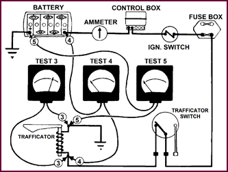 If a reading is
obtained, remake the connection and retest.
If a reading is
obtained, remake the connection and retest.
Figure 105. Circuit diagram for Tests 3,
4, and 5.
Simplified
Trafficator Circuit
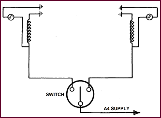 As used on current production vehicles this circuit was
also used on earlier vehicles without a trafficator warning light. The control
is by a self-cancelling switch located on the steering column and is equally suitable
for a facia mounted switch.
As used on current production vehicles this circuit was
also used on earlier vehicles without a trafficator warning light. The control
is by a self-cancelling switch located on the steering column and is equally suitable
for a facia mounted switch.
Figure 106. Simplified trafficator
wiring circuit – 1.
The trafficator supply is via the ignition
switch and fed to control box A3, across the fuse to A4 and connected to the
centre terminal of the switch.
From each of the side terminals of the
switch, a wire is taken to the corresponding trafficator.
Where it is desired to incorporate a
warning light on an existing installation, the assembly may be connected as
shown in the following illustration.
Trafficator Wiring Circuit With Warning Light
The circuit shown here is in use where
trafficators are fitted together with an indicator warning light. The supply to
the indicator switch is from the A4 terminal protected by a fuse and directly
controlled by the ignition switch. When installed on the vehicle, a GREEN cable
is run from the A4 fuse terminal direct to the switch main terminal.
A GREEN and RED cable to the left hand
trafficator, and GREEN and WHITE cable to the right hand trafficator complete
the circuit.
Figure 107. Trafficator wiring circuit –
2.
The warning light is connected across the
trafficator feed terminals of the switch. When either trafficator is switched
on, the warning light makes a parallel circuit to earth via the solenoid
of the other trafficator.
The current taken by the warning light will
only be small and insufficient to operate the trafficator.
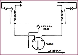 Trafficator Wiring
Circuit Used On Earlier Jaguar And Rover Cars
Trafficator Wiring
Circuit Used On Earlier Jaguar And Rover Cars
Figure 108. Trafficator wiring circuit –
3.
The special feature of this arrangement is
the warning light circuit. This can only be completed by the switch and arm
bulbs when the trafficators are in the fully raised position.
The advantage of this circuit is that with
either an arm bulb fracture or the arm sluggish and not attaining the fully
raised position, there would be no illumination of the warning light.
The trafficator and warning light supply
wires are taken off the A4 terminal on the control box.
A BLUE and BLACK cable from the warning light
is connected to an extra terminal on one trafficator, with a cross feed to the
opposite trafficator.
Special Circuit
For Jaguar And Rover Cars
This arrangement had special features.
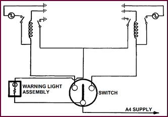 The trafficators incorporated two switches; the warning
light circuit was only completed when the signal arm was in the fully raised
position. The cable from the warning light was connected to an additional
terminal on the trafficator, then to a special earthing switch built into the
unit and earthing on the plunger in the fully raised pos-ition. An additional switch
in the trafficator is for the arm bulb only, which completes the circuit in the
fully raised position.
The trafficators incorporated two switches; the warning
light circuit was only completed when the signal arm was in the fully raised
position. The cable from the warning light was connected to an additional
terminal on the trafficator, then to a special earthing switch built into the
unit and earthing on the plunger in the fully raised pos-ition. An additional switch
in the trafficator is for the arm bulb only, which completes the circuit in the
fully raised position.
Figure 109. Trafficator wiring circuit –
4.
It will be observed that when the ignition
is switched on, the supply is to the centre terminal and connected also to one
side of the warning light. The other side of the assembly is connected to the
earthing switch on the trafficator. This necessitates an additional cable to
either trafficator.
PART FOUR: FLASHING
LAMP DIR-ECTION INDICATORS
General
Four Light Direction Indicators or Flashing
Light Indicators are a method of indicating a driver's intention to make a
change of direction, widely used on American cars and now being fitted to some
British cars as an alternative to the Trafficators.
The arrangement consists of a pair of
lights at the front and rear of the vehicle, actuated by a switch and a
flasher. Alternatively, a suitable amber coloured unit may be placed on each
side of the vehicle.
The general design and lay-out of the
arrangement as applied to the popular car conforms to the following principal
recommendations:
1. Two white or amber lights at the front of the vehicle and
similar amber or red lights at the rear.
2. The lamps must be mounted between 17" (432 mm) and 90° from
the ground and not more than 16" (406 mm) inwards from the side of the
vehicle.
3. They must not be less than 3½ inches2 (22.6 cm2)
– vehicles over 2 tons (2·03 Tonnes) 12 inches2 (77·4 cm2)
– in area and the light shall be diffused by frosted glass or other adequate
means.
4. The power of the lamp shall not be less than 15 or more than 36 Watts.
5. The Flashing indicators may be combined with the vehicle's
existing 'Side and Stop/Tail 'lights, provid-ing that a separate circuit and
separate bulbs or bulb filaments are used.
6. The flashing rate of the lights must lie between 60 and 120 per
minute.
7. The indicators shall be fitted so as to enable the driver to
observe that they are operating; or alter-natively a warning light must be
installed.
Vehicle Showing Position Of Indicator Lamps
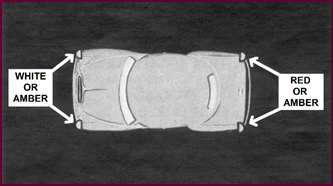 With such an indicator system we need four lamps, one
at each corner of the vehicle, two facing forward and two to the rear.
With such an indicator system we need four lamps, one
at each corner of the vehicle, two facing forward and two to the rear.
Figure 110. Plan view of motor vehicle
showing position of indicator lamps.
All four lamps may show an amber light, or
those at the front may be white and those at the rear red.
To give a visible and unmistakable signal,
the lamps should show an intermittent light; in other words they are made to
flash or wink.
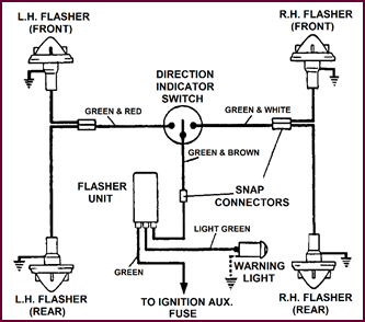 Components Of The
'Flasher' Equipment
Components Of The
'Flasher' Equipment
Figure 111
shows the typical possible units of a flasher
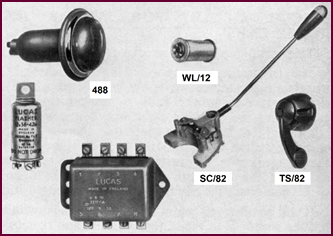 circuit.
Figure 111. Individual components that
form a flashing indicator system.
In the simplest arrangement, however, only
FOUR com-ponents are required:
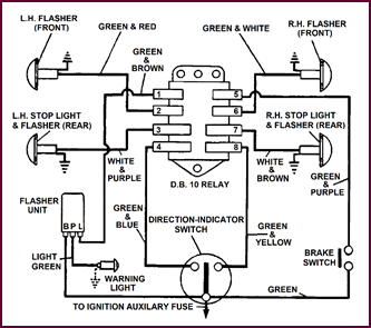 1. Four separate lamps (or Double
Filament Bulbs in the side lamps) and separate rear lamps.
1. Four separate lamps (or Double
Filament Bulbs in the side lamps) and separate rear lamps.
2. A Warning light mounted inside the vehicle.
3. The Flasher Unit.
4. An Indicator Switch. Two types of switch are shown, the one on
the right being the SC82, a non-cancelling switch recommended for use when the
Flasher Set is supplied as an accessory.
The switch shown to the left is the self-cancelling type, the
return being actuated by a cam on the steering column. It incorporates a
warning light in the amber knob on the end of the arm.
A popular variation of this arrangement –
dependent upon the choice of the vehicle manufacturer – is to use the Brake
Stop Lights for the rear indicators.
This requires
a 'Relay' in addition to the other components, and incidentally complicates the
wiring quite considerably.
Circuit With Independent Rear Indicator Bulbs
The simple layout and circuit using the
side lamps at the front end and separate lamps at the rear is shown in Figure
112.
Looking at the lower centre, we see that
the feed is taken from the ignition auxiliary fuse Terminal A4 at the Control
or Fuse box directly to terminal 'B' on the flasher unit. Current passes
through the unit and out to terminal 'L', which is connected to the
centre point of the direction indicator switch.
Here the circuit divides, leading to the
left or right-hand lamps, according to the position of the switch.
Looking at one side only, say the right, we
see that the front and rear lamps are connected in parallel; the circuit to
earth is completed through the lamp filaments.
The indicator warning lamp is connected
between term-inal 'P' of the flasher unit and earth.
Figure 112. Circuit with independent
rear indicator bulbs.
Circuit
Employing DB10 Relay
If, as is frequently the case, the Brake
Stop Lamps are used as Rear Indicators, this circuit diagram shows the general
arrangement.
Figure 113. Circuit employing the Lucas
DB10 relay.
It comprises the same units as before with
the addition of a Relay as shown at top centre. The sole purpose of this is to
put the Brake Stop Lights out of circuit whilst it is functioning as a
direction indicator.
Now to clarify this circuit, note carefully
that the Indicator Switch – centre-bottom of diagram – is used to operate the
Relay only.
The current feed from A4 terminal as before
supplies separate circuits.
1. The Indicator Switch to operate the Relay.
2. The Stop Lamp Switch and then through the Relay to the Stop lamp
bulb filaments.
3. A feed to the Flasher unit. From this unit to the Relay and from
separate contact points in the Relay to the filaments in the Sidelamp and Stop Lamp
bulbs.
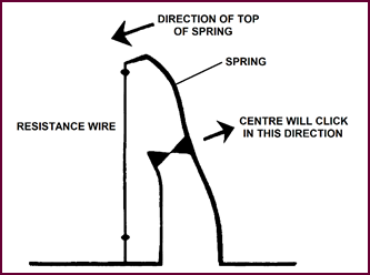 Lastly, there is the Indicator Warning Light which is
fed directly from the Flasher Unit – terminal 'P' through the lamp to
earth.
Lastly, there is the Indicator Warning Light which is
fed directly from the Flasher Unit – terminal 'P' through the lamp to
earth.
The Flasher Unit: Operation Of Thermal Switch
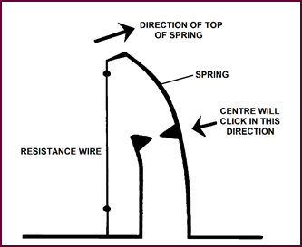 The Flasher unit is basically a Thermal switch for inter-rupting
the current at a pre-determined rate per minute; in other words, it switches
the lamps on and off. The rate of flash is between 60 and 120 times per minute.
This and the following diagrams will make the operation clear.
The Flasher unit is basically a Thermal switch for inter-rupting
the current at a pre-determined rate per minute; in other words, it switches
the lamps on and off. The rate of flash is between 60 and 120 times per minute.
This and the following diagrams will make the operation clear.
Figure 114. Basic flasher unit –
contacts open.
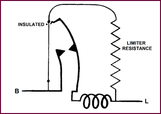 On the left of Figure 114, we see a piece of
resistance wire, anchored at the bottom end to the frame of the unit, and at
the top to a spring, so that it is always kept under tension. The spring is a piece
of thin metal, so shaped that when it is bent, a 'buckling' or 'click' action
takes place in the centre. The centre of the spring carries one of a pair of
contact points.
On the left of Figure 114, we see a piece of
resistance wire, anchored at the bottom end to the frame of the unit, and at
the top to a spring, so that it is always kept under tension. The spring is a piece
of thin metal, so shaped that when it is bent, a 'buckling' or 'click' action
takes place in the centre. The centre of the spring carries one of a pair of
contact points.
These are normally open. When current
passes through the wire it will get hot and expand.
The top of the spring will move in the
direction shown in the diagram. Because of the click action the centre will
move in the opposite direction to the top. In practice, the points will be
snapped closed when the top of the spring has travelled a pre-set distance. In
simple terms this so-called 'Click' action is produced by distorting a
specially shaped strip of metal in the vertical plane whilst it is already under
stress in the horizontal plane. This principle is widely used in the
construction of micro switches. It en-sures a quick positive action for a very
small movement.
The closing of the points by-passes the hot
wire and cur-rent will no longer flow through it. It immediately begins to
cool, and contracts, consequently reversing the action.
As we see in the second illustration, the
points are now closed, by-passing the resistance wire. The latter is thus
contracting. The top of the spring will be pulled back to the left and, at a
critical point, the contacts will click open. The resistance wire is again in
circuit and current will pass through it; the heat will cause it to expand and
the points on the blade will 'click' closed again.
We will point out that current will
continue to pass through the resistance wire when the contacts are open, as we
do not completely break the circuit – however let us look at the next picture.
Figure 115. Basic flasher unit – points
closed.
The Limiter
Resistance
Here we see what happens in the complete
unit. Our hot-wire is shown on the left and in the centre the click spring and
contacts. But we now show a resistance in series with the hot wire. This serves
two purposes: it limits the amount of current passing through the flasher bulbs
to below that at which they will light. It also prevents any sudden surge of current
from damaging the wire when the indicators are switched on. Current passing
through the wire will cause it to expand; the spring will click over once
again, and the contacts close.
Figure 116. Flasher unit – contacts
open.
Operation Of
The Pilot Light
Having produced the Flashing light,
provision has to be made for the Dashboard Warning Light. This is done by means
of what is termed a 'Pilot Light Coil'.
When the main contacts close, the current
to the lights, now passes through this coil. As soon as the coil is energised,
it moves a small armature which closes a pair of contacts in the base of the
unit. This completes the lead to the pilot lamp, causing it to flash in
sympathy with the main bulbs.
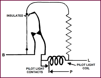 However, the pilot coil is so designed that it will operate
the pilot light contacts when 36 to 40 Watts are being consumed. Should less
current flow, for example if one bulb failed, the contacts will not close and
the pilot light will not flash, thus warning the driver that one of his
direction indicators is not working.
However, the pilot coil is so designed that it will operate
the pilot light contacts when 36 to 40 Watts are being consumed. Should less
current flow, for example if one bulb failed, the contacts will not close and
the pilot light will not flash, thus warning the driver that one of his
direction indicators is not working.
Figure 117. Flasher unit – contacts
closed.
Three leads marked 'B', 'P'
and 'L' are brought out to terminals in the base of the unit. The one marked
'B' for battery will normally be connected to the A4 terminal on the
control box. The centre terminal 'P' is wired to the pilot lamp. The terminal
marked 'L' will feed the indicator lights, via the indicator
switch or a relay if fitted.
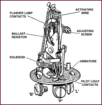 The Flasher Unit –
Fitting
The Flasher Unit –
Fitting
Figure 118. The components inside a
flasher unit.
Here we have
the complete Flasher with the cover removed.
As in most Thermal Switches this unit is
susceptible to damage by the ingress of dust or moisture. Additionally, the
temperature must be kept uniform to maintain the correct rate of Flash. For
these reasons the unit is her-metically sealed by means of an aluminium cover.
This of course precludes the possibility of any adjustment in service, but in any
case this is a tricky business that can only satisfactorily be done in an
instrument Repair Shop.
The following precautions are necessary to
ensure satisfactory performance from the flasher:
1. The mounting position must be vertical, with the ter-minals at
the bottom. A position free from engine vibration should be chosen.
2. The correct bulbs must be used, i.e., originally TWO 18 Watt,
now TWO 21 Watt filaments on each side.
3. Not more than 4 amps. should pass through the unit at 12-volts,
i.e., 48 Watts. Damage may be caused if this is exceeded.
4. Less than 36 Watts will not
operate the Warning Light.
Testing can be carried out by applying 12-volts
to the 'B' terminal and connecting a pair of 21 Watt lamp bulbs to the 'L'
terminal and a 12-volt 2·2 Watt Ignition Warning bulb to the 'P'
terminal.
The Flash rate
60 to 120 per minute can be checked by coun-ting the
Flashes over 10 seconds and multiplying by SIX.
Care must be taken with this lightly-built
unit both in Transit and Storage to prevent it becoming damaged.
The DB10 Relay
The Relay which has to be fitted when the
Stop Lamps are used as direction indicators is the type DB10.
This is an EIGHT terminal Relay with the
following layout:
Lug 5. Feed from Stop Lamp Switch Lead to 'L' terminal on
Flasher Lug 1.
Lug 6. To Left and Right Front Indicators Lug 2.
Lug 7. To Left and Right Rear Indicators Lug 3.
Lug 8. To Direction Indicator Switch Lug 4.
Note: Lug numbers are terminal lugs
identified in Figure 119 below.
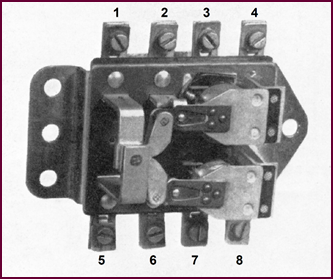 Simply connect the correct wires in this order and all
will be well. Refer to Figure 113.
Simply connect the correct wires in this order and all
will be well. Refer to Figure 113.
Figure 119. The DB10 relay with numbered
terminal lugs.
The function of this unit is to interrupt
the current supply to either stop lamp when it is to be used as a direction
indicator light.
The DB10 Relay In
The Rest Position
The electrical operation of this Dual Relay
is quite simple if we follow it through in stages.
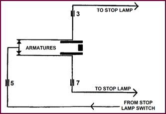 This diagram shows the current carrying component of
the Relay when it is not being used for indicating purp-oses, i.e., at the rest
position.
This diagram shows the current carrying component of
the Relay when it is not being used for indicating purp-oses, i.e., at the rest
position.
Figure 120. DB10 relay showing stop lamp
circuit.
The two armatures – centre of diagram – are
then making contact with two points which are connected together, left; the
current feed is through terminal lug '5' from the Stop lamp switch.
Each armature at its fixed end is connected
to a stop lamp through terminals '3' and '7'. With the relay in
this position, both lamps will light when the stop lamp switch is closed by the
action of the brake-pedal.
Operating
Solenoid And Contact Sets
In this diagram we see that the two
armatures are still at rest, and the stop lamps will operate as we described for
Figure 120.
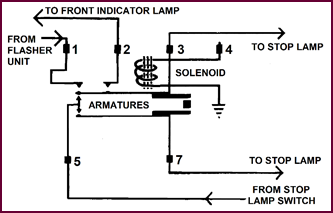 We said that the unit is actually two relays mounted
together, and the armatures we show form part of them.
We said that the unit is actually two relays mounted
together, and the armatures we show form part of them.
Figure 121. DB10 relay, at rest with one
pair of contacts added into the diagram.
Next, we have added two contacts above the
top arm-ature, which is operated by the solenoid.
One contact is connected to the flasher
unit through term-inal '1', whilst the other contact carries current to
the front indicator lamp on one side of the vehicle via terminal '2'.
One end of the single operating Solenoid
shown is earthed to the frame of the relay, and the other is brought out at
terminal '4'. This terminal connects to one side of the indicator
switch.
Turning To The
Right
When the indicator switch is moved to the
right, the solenoid shown is energised. This lifts the armature and closes the
pair of points.
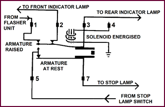 Current then flows from the Flasher unit through terminal
'1', across the armature and to the front indicator lamp via
terminal '2'. The rear indicator is fed via terminal '3'.
This lamp can no longer act as a stop light because the current supply from terminal
'3' is now broken.
Current then flows from the Flasher unit through terminal
'1', across the armature and to the front indicator lamp via
terminal '2'. The rear indicator is fed via terminal '3'.
This lamp can no longer act as a stop light because the current supply from terminal
'3' is now broken.
Figure 122. DB10 relay, one solenoid
energised.
The other armature is still at rest and you
will notice that the feed from the stop-lamp switch remains intact to the stop
lamp. This means that the stopping signals can still be given on the left-hand
side of the vehicle when the turning signals are in use on the right-hand side
or vice versa.
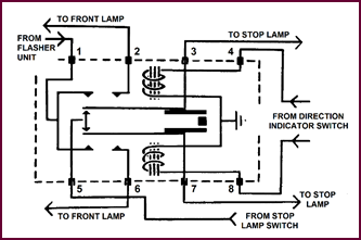 The Complete Relay
Assembly
The Complete Relay
Assembly
Figure 123. Circuit diagram for the
complete DB10 relay.
Here we have the complete assembly. We
agree that the diagram makes this simple piece of equipment look complicated.
However, you
can see that it is quite ingenious and compact.
The unit is fully sealed to prevent ingress
of dirt and moisture and, even if the mechanism were easily access-ible, it
would be a time-wasting proposition to attempt adjustment or repair.
The Lamps
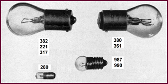
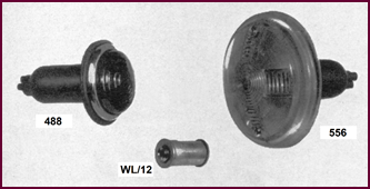 When separate lamps are fitted to a vehicle, there are
two types available: the type 488 seen on the left in Figure 124, and
the 556 seen on the right.
When separate lamps are fitted to a vehicle, there are
two types available: the type 488 seen on the left in Figure 124, and
the 556 seen on the right.
Figure 124. Flashing indicator lamps.
Type 488 Lamp. This is a flush-fitting lamp consisting of a moulded rubber body
holding a fluted glass and chromium plated rim. When used for direction
indication it can be supplied with a white, red or amber glass, and either
single or double filament bulbs (6 or 12-volts).
The models fitted with white or red glasses
used for giving indication signals as well as the side or rear lighting are
fitted with two pole bulb-holders having off-set bayonet slots to take a double
filament bulb of the popular types No. 361 or 380.
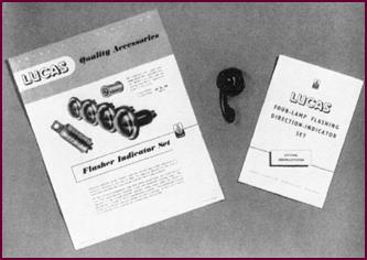 The flasher set supplied as an accessory consists of
four of these lamps with amber glasses, each having single filament 12-volt 21 Watt
bulbs No. 382.
The flasher set supplied as an accessory consists of
four of these lamps with amber glasses, each having single filament 12-volt 21 Watt
bulbs No. 382.
Type 556 Lamp. This lamp has been specially designed for commercial vehicles. It
has a moulded Diakon plastic lens, amber in colour, with an area of 12 inch2
(77.4 cm2). It is held in position by two screws. The body is
moulded rubber fitted over a steel baseplate and a single filament bulb holder
takes a 21 Watt bulb.
The Warning Light is the type WL/12, also used as a Headlamp Main Beam Warning Light.
It has a die-cast body, with small amber polystyrene lens in a chrome bezel. A
miniature screw type bulb is used, fitting in a standard bulb holder.
The Bulbs
Separate Indicator Lamps. The correct bulb is No. 382. This is a 12-volt 21 Watt
single-filament bulb with a single contact cap.
The original bulb used was the No. 221 (12-volt
18 Watt).
The corresponding 6-volt bulb is No. 317 (6-volt
18 Watt).
The Combined Stop Tail and Indicators use Bulb No. 380. This is the 12-volt bulb with 6 and 21 Watt filaments.
It has a small bayonet cap (9/16" dia.) with off-set
pins to ensure that the bulb is correctly positioned.
The 6 Watt filament is used for the side or
rear light and the 21 Watt filament for the Indicator or Stop Light.
The stop lamp filament was originally 18 Watts
but was subsequently increased to 21 Watts to increase the bril-liance. This
increase is noticeable when the indicator is used in strong sunlight. If the 6/18
Watt bulb is required as a replacement in one of the earlier installations, the
correct number is 361.
Figure 125. Flashing indicator bulbs.
Warning Light. The bulb used is No. 987, 12-volt 2·2 Watts, with a Miniature
Edison Screw Cap (M.E.S.) This is the same type of bulb as used in the ignition
warning lights where no resistance is fitted; it is also used extensively for
instrument panel illumination. For the 6-volt system a similar bulb No. 990 (6-volt
3 Watts) is used.
A new type of warning light bulb, known as
a Lilliput Bulb is shown at the extreme bottom of Figure 125. It is bulb
No. 280, fitted to the TC82 Direction Indicator Switch and is only available in
12-volt.
The Flasher Set
As An Accessory
A Flasher Indicator Set is now available as
an accessory for vehicles not already fitted
with this type of indicator. This is fully described and detailed in our Sales
Leaflet No. 1100.
Figure 126. The Lucas flasher kit as an
accessory.
The set consists of FOUR Type 488 Lamps, a Flasher
Unit and a Warning Light. No Direction Indicator Switch is supplied as
generally the existing self-cancelling switch on the steering column will be used.
For vehicles where this is not so, an Indicator Switch No. TS82 is available.
A Fitting Instruction Leaflet is supplied
with each set, the wiring circuit being that which we examined at Figure
112, on Page 40.
The correct size cable for either the 12 or
6-volt layout is 14 strand/0·012 auto-cable. The colours we recommend for new
car installations are:
1. Ignition Auxiliary fuse 'A4' to Terminal 'B' on the Flasher
Unit: GREEN.
2. Terminal 'P' on the Flasher to the warning light: LIGHT GREEN.
3. Terminal 'L' on the Flasher to the centre terminal on the Direction Indicator Switch: GREEN and BROWN.
4. Direction Indicator Switch to the lamps on the near-side of the
vehicle: GREEN and RED; and to the off-side: GREEN and WHITE.
 L559 Flasher Indicator
Set
L559 Flasher Indicator
Set
Figure 127. The L559 flasher indicator
set.
A TWO Lamp Set is also provided for 'after
sales' fitment and is available for both 6 and 12-volt working. It is mainly
applicable to earlier types of cars, vans, taxis, etc., and as an interesting
and profitable Service Sales line is worthy of some detailed examination.
The set comprises the components shown in Figure
127, which, it will be noticed does not include a switch.
Where a trafficator switch is already
installed this will be quite suitable. In the event of a switch being required the
most popular suitable model is the TS82 Panel mounting TWO-WAY and OFF Switch
as illustrated on the right.
The Circuit
Arrangement
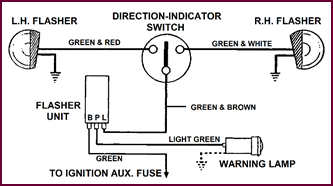 The very simple circuit arrangement shown in this illus-tration
can be easily followed.
The very simple circuit arrangement shown in this illus-tration
can be easily followed.
Figure 128. L559 circuit diagram.
Current supply from the A4 terminal at the
control box or fuse panel connects directly to terminal 'B' (battery) on
the Flasher unit and from terminal 'L' (Lamps) to the centre contact of
the TWO-WAY and OFF panel mounted switch.
From each side of this switch the supply is
wired directly through the lamp bulbs to earth.
As with the FOUR Lamp Sets the warning lamp
bulb is wired directly from terminal 'P' (Pilot) on the Flasher unit
through the warning lamp to earth.
The cable required for installation will be
size 14/·012, Master Colour Green and for convenience in subsequent service,
the tracer colours as shown in the diagram should be used if possible.
The Type FL3 Flasher
Unit
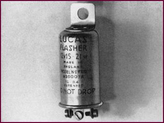 This unit is special for the TWO lamp set and whilst
having the standard flash rate of 60 to 120 per minute is designed for a
current of 15-21 Watts only.
This unit is special for the TWO lamp set and whilst
having the standard flash rate of 60 to 120 per minute is designed for a
current of 15-21 Watts only.
Figure 129. The type FL3 flasher unit.
This unit is part number 35007 for the 12-volt
and 35008 for the 6-volt model.
When installing a set it is important that
the Flasher unit should be positioned where it will not be affected by engine
vibration or exposure to the weather and mounted upright with the wiring
terminals pointing downwards.
As a point of interest it may be noted that
the Flasher Unit for the Four Lamp Set carrying 42 Watts is FL3 Part No. 35003
for the 12-volt and Part No. 35005 for the 6-volt.
It will be appreciated at once that the TWO
and FOUR Lamp Flasher Units are not interchangeable.
The Warning
Lamp Type WL12
The Warning Light shown should be installed
in a prom-inent position on the facia panel directly in the driver's line of
vision as far as possible.
This lamp is a single hole fixing model and
the bulb is installed from the rear as shown.
The correct bulbs are as follows:
12-volt sets Lucas 987 2·2 Watts MES
6-volt sets 990 3·0 Watts MES
MES Miniature Edison Screw.
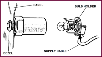 Figure 130. Lucas Type WL12 warning lamp.
The No. 559 Lamps
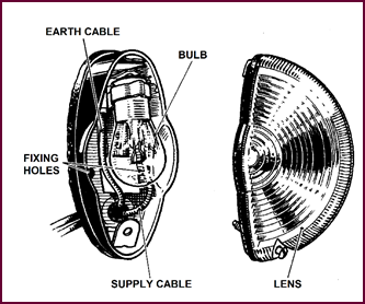 These should be installed in a conspicuous position at
the widest part of the vehicle not more than 7' 6" (1,980 mm) from the
ground or less than 1' 5" (432 mm), and not more than 6' (1,829 mm) behind
the windscreen. They should also be mounted upright in order that the maximum
amount of light be projected towards oncoming traffic.
These should be installed in a conspicuous position at
the widest part of the vehicle not more than 7' 6" (1,980 mm) from the
ground or less than 1' 5" (432 mm), and not more than 6' (1,829 mm) behind
the windscreen. They should also be mounted upright in order that the maximum
amount of light be projected towards oncoming traffic.
Figure 131. The Lucas 559 flashing
Indicator lamp.
In the detailed Instruction Leaflet No. 1210
supplied with each set a drilling template is provided for convenience of
installation.
The general arrangement of the lamp is
clearly shown in Figure 131, and on the back is shown the flexible
rubber mounting pad which is supplied with it.
To ensure satisfactory operation it is
essential that lamp bulbs of the correct Wattage are used, and the replace-ment
numbers specified below will be useful to note, particularly in the event of
any service trouble being encountered with the Flasher Unit, in which case the
first thing to do will be to check the bulbs.
12-volt sets Lucas No. 382 21 Watt SCC
6-volt sets Lucas No. 317 18 Watt SCC
The Switch
If the vehicle has been previously fitted
with direction indicators the existing switch can of course be used.
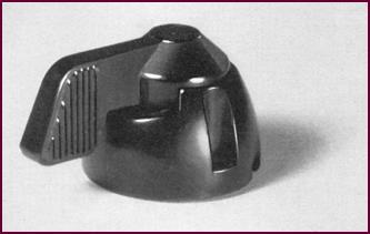 When installing a new switch, care in choosing a position
of maximum convenience and accessibility to the driver's hand is of value.
When installing a new switch, care in choosing a position
of maximum convenience and accessibility to the driver's hand is of value.
Figure 132. Lucas TS82 switch.
One of the most popular and readily
available switches for panel mounting is the model TS82 as illustrated, but any
other type of TWO-WAY and OFF switch capable for carrying 3 ampéres may be used.
The Wiring
The wiring up of the TWO Lamp Indicator set
will be as laid out in the diagram shown in Figure 134 and is an
operation which may frequently be simplified by the use of snap connectors.
 If the vehicle has no convenient fuse point
available from which to take the current supply it may be connected from a point
on the Ignition switch circuit such as the coil terminal on the ignition switch
or the 'SW' terminal of the ignition coil itself. This will preclude the
possibility of the indicators being left ON when the engine is stopped prior to
getting out of the vehicle.
If the vehicle has no convenient fuse point
available from which to take the current supply it may be connected from a point
on the Ignition switch circuit such as the coil terminal on the ignition switch
or the 'SW' terminal of the ignition coil itself. This will preclude the
possibility of the indicators being left ON when the engine is stopped prior to
getting out of the vehicle.
Figure 133. Circuit diagram for two lamp
flasher set.
Care should be taken to provide an
effective earth from each Indicator lamp and also the warning lamp, by
installing separate earth wires wherever necessary.
A particular useful hint is to test out the
wiring after installation with the Flasher unit itself out of circuit. To do
this, before connecting the feed to the fuse disconnect the three flasher unit
connections and join them all together. Connect the feed wire to the current
supply terminal and then operate the indicator switch. If anything is incorrect
it will immediately show up and can be rectified without risking damage to the
Flasher Unit itself.
Service Testing
The Flasher Installation – Separate Indicators
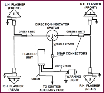 Having told you all about the indicator equipment, we
can now consider how to test this equipment in Service. To do this, we will
divide the procedure into the two basic circuits.
Having told you all about the indicator equipment, we
can now consider how to test this equipment in Service. To do this, we will
divide the procedure into the two basic circuits.
Figure 134. Circuit diagram for testing
installation with four separate lamps.
We start with the simple circuit first,
i.e., that employing four separate indicator lamps.
1. With the ignition switch on, check for a voltage reading at
the following points:
a) A4 Fuse.
b) 'B' Terminal of the Flasher Unit.
c) 'L' Terminal of the Flasher Unit.
A reading at both these terminals of the Flasher unit proves
continuity of the flasher unit itself. If there is a reading at one terminal
only, the unit should be changed.
d) The Feed Terminal of the Direction Indicator Switch.
2. To check the remainder of
the wiring and system.
Turn the indicator switch to either side, when both lamps (one
rear and one front) will 'flash'. If any one lamp does not light, it is an easy
matter to check through the wiring with a voltmeter for an open circuit or
blown bulb, etc.
Service Testing
The Flasher Installation – Incorporating DB10 Relay
Service testing is slightly more
complicated when a DB10 relay is incorporated in the circuit.
The procedure then would be as follows:
1. Switch on the Ignition.
Battery voltage should be registered between earth and the
following Points:
a) A4 terminal on fuse board – if no reading is obtained,
check fuse and A3 supply.
b) Direction indicator switch feed terminal – if inaccessible, check at nearest possible point,
e.g., base of steering column, snap connector, etc.
c) Flasher Unit feed terminal 'B' – if letter 'B'
is not visible, reference to test (d) below shows that voltage should be
registered at the two directly opposite terminals.
d) Flasher Unit terminal 'L' (opposite 'B') a reading proves
continuity through the unit. No reading indicates a faulty unit.
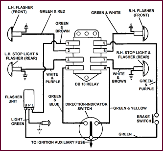 e) DB10 relay No. '1' terminal –
voltage registered only if a reading was obtained at 'L' .
e) DB10 relay No. '1' terminal –
voltage registered only if a reading was obtained at 'L' .
Figure 135. Testing a flasher circuit
that incorporates a Lucas DB10 relay.
2. Connect a temporary feed wire from the A4 term-inal, in turn,
to the following terminal lugs of the DB10 relay.
a) No. '3' and No. '7'.
Both stop lamps should light each time. If the same lamp does
not light in either test, the fault must be in the wiring to that lamp, or in
the bulb, the holder, earth, etc.
If alternate lamps light individually during both tests,
the fault will be in the relay.
b) No. '2' and No. '6'.
Each front indicator lamp should light. If not, check bulb,
holder, lamp earth and wiring (from relay to lamp).
c) No. 4 and No. 8.
Each relay should operate in turn, accompanied by flashing of one front and one rear indicator
lamp.
If neither relay operates, first check that the unit is
earthed. If it is, the DBl0 is faulty.
If one relay does not operate – internal fault in the DB10.
If one relay operates and front and rear indicator lights on
that side flash, but both lamps do not flash on the other side, even though
their relay can be heard closing, the DB10 is faulty.
If both relays close, but none of the lights flash, the fault
can be in either the DB10 or the flasher unit. In which case, eliminate one or
the other by linking terminals '1' and '3' of the DB10.
If the flasher now operates, the DB10 is faulty. No change indicates
a faulty flasher.
3. To check the remainder of the wiring and the indicator switch.
Turn the switch first to one side and then to the other. Each
relay will be heard to close and all lights should flash. If this is not so,
check wiring between switch and DB10 relay. (Terminals '4' and '5'.)
If wiring is in order, check switch itself.
4. Final checks.
a) Pilot Light – This should flash in sympathy with
indicators.
If it is not operating, check with voltmeter between earth and
terminal 'P' on flasher unit. A reading should be obtained at every
flash of the indicators. No reading proves flasher unit faulty. If correct
reading is obtained, check pilot light bulb and wiring.
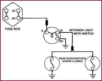 b) Rate of flash.
N.B. If flashing rate is not within the prescribed limits, do
not suspect the flasher unit before ascertaining that the indicator lamps are
of the correct Wattage.
Incorrect bulbs will also seriously affect the operation of the
pilot light.
Additional Test for Stop Lamps.
This test need only be carried out if the flasher
system is in order, but the stop lamps do not operate.
Voltage should be registered at the
following points:
(i) Stop lamp switch, feed terminal – if this is inac-cessible
depress the brake pedal and check at (ii) below:
(ii) DB10 Relay No. '5' terminal – no reading indicates a
fault in the wiring from the stop-lamp switch, a faulty switch or an incorrectly
adjusted brake linkage.
PART FIVE:
INTERIOR LAMP CIRCUITS AND DOOR OPERATING SWITCHES
General
On several recent saloon cars the lamps
required for interior illumination and which are generally operated by a plain
ON-OFF switch, have been fitted up with supple-mentary plunger switches
operated by the opening and closing of the doors.
Generally the arrangement is that upon
opening either door the switch will be ON and one or more interior lamps will
light up. When the door is closed – presumably after the entry of the
passengers – the switch will again be OFF and the lights will go out.
If for any reason the lights are still
required after entry they can be switched ON and OFF by means of a separ-ate
lever type switch usually built into the lamp itself.
As these individual wiring arrangements may
be difficult to follow out when seen in situ on the vehicle, they will be
illustrated and described separately.
In all the different arrangements it should
be noted that the current supply is taken from the A2 fuse terminal and
connected directly to the lamp bulb and the switch and switch wire is on the
earthed side.
The cable used
for these circuits is usually 14/012 BROWN and GREEN
from the fuse, and BLACK on the earth side.
Various types of lamps are installed, and
altogether some FOUR models of lamp bulbs are in use. A particular type can
most conveniently be obtained by reference to the Lucas parts list for that
model, or the bulb replacement list if the lamp fitted is not of Lucas manufacture.
Interior Light
Circuit – Two Door Switches:
Austin A40, A50
And A90 Models 1954–55
The current supply from the A2 fuse is
junctioned through a 'Snap' connector directly to the light bulb in the
interior lamp at (Terminal 'A').
Figure 136. Door switch circuit for
Austin A40, A50 and A90 (1955).
For local
operation the Switch 'B1' is connected direct to earth.
When fitted with TWO door switches as shown,
an ad-ditional cable is wired from the bulb connection at 'B', by means
of a snap connector to one side of each door switch 'C' and 'C1',
the other switch terminals connecting directly to earth.
With the doors closed both switches will be
OFF, but when either door is opened the switch will be ON and the interior lamp
will remain alight until either or both doors are re-closed. Optional control
of the lamp is still available from the local switch 'B1'.
Interior Lamp
And Door Switch Circuit:
Wolseley 6/90,
1955
On this model using two interior lights it
should be observed that whilst the circuit is basically the same as the one just examined, for convenience the wiring arrange-ment
is slightly different.
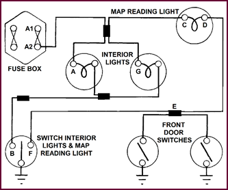
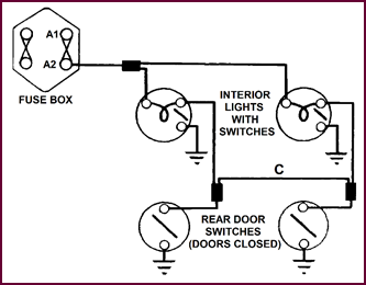 The lamp on each side is connected directly to its nearest
door switch through a snap connector and to enable both lamps to be brought on
when either door is opened an inter-connecting cable 'C' is looped between
the two snap connectors.
The lamp on each side is connected directly to its nearest
door switch through a snap connector and to enable both lamps to be brought on
when either door is opened an inter-connecting cable 'C' is looped between
the two snap connectors.
Figure 137.
Door switch circuit for the Wolseley 6/90 (1955).
Local control is obtained by the individual
switches on each light.
Interior Lamp
And Door Switch Circuit:
 Humber Mk. VI And Riley
Pathfinder Models
Humber Mk. VI And Riley
Pathfinder Models
Figure 138. Door switch circuit for
Riley Pathfinder and Humber Mk VI (1955).
Although there are two interior lamps with their
indepen-dent switches on these cars, the circuit is so arranged that each interior
lamp is connected independently to its own door switch.
Interior And
Map Reading Lamp Circuit:
With Panel And Door Switches For:
1955 Mk. VII
Jaguar
On this model TWO interior lamps are
supplemented by a 'Map Reading' lamp and the control for all three is provided
by means of a panel mounted TWO-WAY and OFF switch. Additionally, DOOR switches
are installed in the FRONT doors only.
Figure 139. Door switch circuit for Jaguar
Mk VII (1955).
Following the circuit through, it will be
seen that the current supply from A2 is taken via a snap connector direct to
one side of both interior lamps and also the map reading lamp, as shown at 'A',
'G' and 'C'.
The return
from both interior lamps is joined by a snap con-nector
to terminal 'B' of the panel switch. The centre or common terminal 'C' of this switch being connected
to earth.
The return from the map reading lamp 'D'
is via the snap connector 'E' to the other terminal 'F' of
the panel switch.
Now for the Door switches. The return from
the map read-ing lamp only is connected by the snap connector 'E' to one
side of each door switch and across both switches to earth. Thus, if either
door is opened the switch will bring on the map reading lamp only, which will
again be auto-matically switched off when the door is closed.
Document
Restorer's Note
Once again, the course session stresses
the requirement for good earthing contacts. This is particularly so when
carrying out the recommended tests.
Observe Domestic Science notions – keep
earth contacts clean and soundly tight.
Mike
Allfrey.
Jowett
Car Club Of Australia Inc.