PART ONE: OBLIGATORY
LIGHTING
We shall not attempt to trace the history
of vehicle lighting from the early days of the carriage to the modern motor
vehicle. However, the distinction which existed from the very beginning, that
which can be summed up as 'see' and 'be seen' is still prevalent to-day.
 In England, the carriage lamp became the 'obligatory'
lamp or side-lamp; it enabled the vehicle 'to be seen'. In other words it
merely indicated the position on the road.
In England, the carriage lamp became the 'obligatory'
lamp or side-lamp; it enabled the vehicle 'to be seen'. In other words it
merely indicated the position on the road.
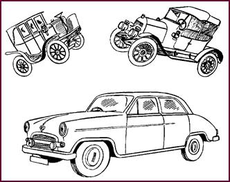
Figure 1. Edwardian, vintage and modern styles.
As the speed of vehicles increased, it
became imperative 'to see' as well as 'to be seen' and so we have progress-ively
seen the introduction of headlights, long-range driving lights, pass lamps, fog
lights, in fact all the additional 'extras' considered so necessary to modern
motoring.
For 'extras' they are in the eyes of
English law, and optional at that; side and rear lamps, together with rear
number plate illumination still constitute the only 'obligatory lighting' for
vehicles in the British Isles.
It is with this lighting that we shall concern
ourselves at the moment. We shall start with a review of modern side lights;
carry on with rear lighting, including stop-tail, number plate lamps, and
reflectors; and then show how the circuits for this lighting appear on the
average vehicle.
Modern Side
Lights
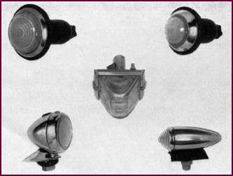
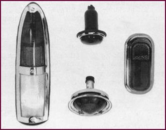
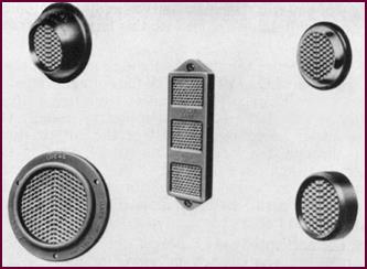
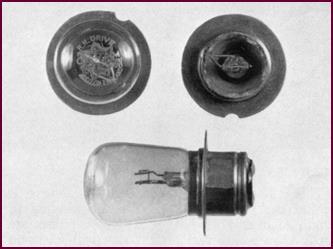
In Figure 2, you see just a few
examples of modern Lucas side-lamps. There are various shapes, sizes and mount-ings
which conform to the constructional requirements of the particular vehicle.
The L488 for instance is used on cars where
stem or spigot fixing is not convenient. It is a flush fitting lamp, consisting
of a strongly moulded rubber body encasing a fluted glass and chromium-plated
rim. The L489 is similar in construction but with a smaller glass. The rim and
glass assembly of these lamps is removable by inserting a coin or screwdriver
between the rim and rubber base.
The LD109 on the other hand is of more conventional
design and spigot mounted. The rim is located by a single screw to facilitate
bulb replacement.
The L516 is a streamlined lamp, specially
designed to match the contours of the car body.
The L545 is one of our latest side-lamps. It
is provided with a bulb-holder suitable for taking a double filament bulb. One
filament gives the normal side-light; the other is used as a 'flashing
indicator'.
Figure 2.
Lucas side-lights. Top left: L488; Top right: L489; Centre: L545; Lower left: LD109 and, lower right: L516.
The bulbs used in the above lamps are as
follows:
Lamp L488
No. 361) a 12-volt, double filament bulb with a rating of 18/6 Watts. The 6 Watt
filament serves as the side-light, whilst the 18 Watt is used for many
applications as a 'flasher' direction indicator.
The L489 is fitted with a No. 222
bulb. This is a single contact type rated at 12-volt 4 Watt.
Both the L545 lamp and the L516
take the same bulb, No. 222. Where the L545 is used as a flasher and side-light
combined, the No. 316 double filament bulb is used.
The LD109 model employs bulb No. 207,
a 12-volt bulb rated at 6 Watts.
Side Lamp
Installation
Side-lamps are positioned on British
vehicles to conform to the 'Lighting Regulations' in force in Great Britain.
The regulations concerning the positioning
of these lamps on cars and light-commercial vehicles state:
1. Both lamps must be fitted at equal height and not exceeding five
feet from the ground.
2. The lamps must be fixed so that no part of the vehicle or its
equipment extends laterally on the same side as the lamp more than twelve
inches beyond the centre line of the lamp. Mirrors and direction indicators in
the operating position are ex-cluded when making this measurement.
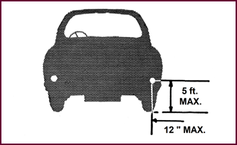 The maximum Wattage of the bulbs should not exceed 7 Watts.
Figure 3. Side-lights' installation
requirements.
Stop Tail Lamps
Nearly all our car tail lamps are combined
in one assem-bly with a stop lamp, the latter being operated by the brake
pedal. Figure 4 shows a cross-section of the lamps we produce to-day.
Let us examine their main construct-ional features.
The 488 is the same lamp as the side-lamp
we have already shown you, but fitted with a red lens.
 One of the latest developments in rear lamp design is seen in the
546 lamp. A Reflex reflector is moulded into the actual lens itself, forming
the top section of the unit. The centre section houses a double filament bulb
which provides the normal tail and stop lights. A 'flasher' direction indicator
bulb can be fitted in the bottom section. This one unit thus fulfils three functions.
One of the latest developments in rear lamp design is seen in the
546 lamp. A Reflex reflector is moulded into the actual lens itself, forming
the top section of the unit. The centre section houses a double filament bulb
which provides the normal tail and stop lights. A 'flasher' direction indicator
bulb can be fitted in the bottom section. This one unit thus fulfils three functions.
Figure 4. A selection of Lucas stop-tail
lamps, with at left hand side: Model 548; Upper centre: Model 488; Lower
centre: Model 551 and, at right, Model 546.
The 551 lamp, too, embodies many recent
design features. The moulded Diakon reflector, 1½" in diameter, is
situated in the centre of the lens, with a clear surround. The rim is pressed
onto the conical shaped lens, and the assembly fitted to a metal back plate
which contains the bulb holder. To prevent the ingress of water, seating
rubbers are fitted between the lens and the back plate, and also behind the back
plate. A double filament bulb provides the tail and stop lamp lighting.
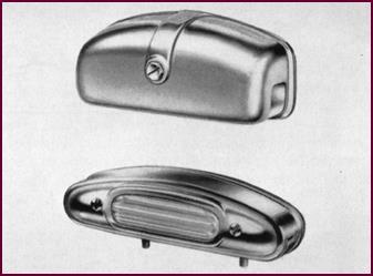
The 548 is the largest of our combined
rear-lamps. It is approximately 11" x 3" (279 x 76 mm) and provides a
reverse lamp in addition to the reflector
and stop-tail lights.
This lamp consists of a die-cast baseplate
into which are sealed two Diakon windows, a red one at the top for the
stop-tail light and a clear one at the bottom for the reverse lamp. The centre
section contains a red reflex.
Although the clear window is provided, the
reverse lamp is an optional extra, and a separate bulb holder assembly is
available.
When the reverse lamp is not required, a
flat steel plate is fitted over the aperture in the base plate.
The following bulbs are commonly fitted to
these lamps:
The 488 model takes the No . 361, a 12-volt
double filament bulb with a 6/18 Watts rating.
The 546 lamp is fitted with a No.
361 bulb serving as the stop-tail light and a separate 'flasher' indicator bulb
No. 221 12-volt 18 Watts.
The 551 lamp employs a No. 380 12-volt
bulb, which contains a 21 Watts flasher or stop-light filament and the normal 6
Watt tail light filament.
Two bulbs are used in the 548 lamp:
the No. 380 rated at 6/21 Watts (12-volt) and No. 382 containing a single 21 Watt
filament for the reverse light.
 Rear Light Installation
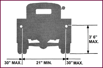
Figure 5. Goods vehicles (over 30 cwt.)
Rear Lamps – must not be more than 3 feet 6 inches from extreme rear.
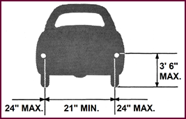
Figure 6. Private Cars, Goods Vehicles
under 30 cwt., Three-wheel Cars and Trailers Rear Lamps – must not be more than
30 inches from the extreme rear.
Rear lamps must be positioned on British
vehicles according to the 'Lighting Regulations' which are en-forced in Great
Britain.
 The specified measurements are clearly visible in the two
illustrations, and we need only add that 'extreme rear' should be taken to
mean the rear of the vehicle when the tail board, luggage grid or any other
adjustable fixture is extended. The bulb rating for rear-lamps should not be
less than 6 Watts.
The specified measurements are clearly visible in the two
illustrations, and we need only add that 'extreme rear' should be taken to
mean the rear of the vehicle when the tail board, luggage grid or any other
adjustable fixture is extended. The bulb rating for rear-lamps should not be
less than 6 Watts.
Reflex
Reflectors
Reflectors, which in the British Isles formerly
came within the category of 'extras' are now legally enforced. They provide
most effective supplementary rear lighting, con-tributing greatly to road
safety.
 All Lucas reflectors are formed by prisms moulded in Diakon. This
formation provides an extremely efficient reflecting surface, so good in fact,
that tests prove that in a headlight beam, reflectors are visible at a thousand
feet or more, showing up as brightly as an ordinary rear lamp.
All Lucas reflectors are formed by prisms moulded in Diakon. This
formation provides an extremely efficient reflecting surface, so good in fact,
that tests prove that in a headlight beam, reflectors are visible at a thousand
feet or more, showing up as brightly as an ordinary rear lamp.
Figure 7. Lucas Reflex Reflectors. Upper
left: RER2; Up-per right: RER5; Centre: RER3; Lower left: RER4 and, lower
right: RER6.
We show you here some of the reflectors we
have de-signed to meet the requirements of all types of vehicles.
The R.E.R.4 is a large model suitable for
fitting to com-mercial vehicles. The strip type R.E.R.3 is also designed for
this purpose. Both these models can be obtained with amber coloured reflectors
for fitting to the sides of the vehicle.
The other three types are all suitable for
fitting to cars and motor-cycles. They are provided with a single self-tapping
fixing screw, and designed for mounting on number plates, rear mud-wings, etc.
The design of the R.E.R.2 makes it suitable
for fitting to curved surfaces.
And here we must make an extremely
important point concerning the positioning of all reflectors.
Their fitting is controlled by the 'Road
Transport Lighting Regulations and these should be carefully studied. The
reflected light is cut down considerably if the reflector is not mounted in the
correct position and, even more important, at the correct angle.
Reflector
Installation
These two illustrations show the specified
positioning for reflectors. We will stress once more that to be properly
effective reflectors must be fitted in the vertical plane and facing squarely
to the rear.
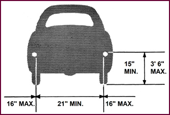
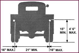 Figure 8. Reflectors on Private Cars, goods Vehicles under 30 cwt.,
Three-wheel Cars and Trailers must not be more than 30 inches from the extreme
rear.
Figure 8. Reflectors on Private Cars, goods Vehicles under 30 cwt.,
Three-wheel Cars and Trailers must not be more than 30 inches from the extreme
rear.
Figure 9. Reflectors on Goods Vehicles
over 30 cwt. must not be more than 30 inches from the extreme rear.
 Number Plate Illumination
Figure 10. Lucas number plate lamps.
Upper: Model 467; Lower: Model 469.
 These are two of the most popular number plate lamps – the only
remaining units in the 'obligatory' category.
These are two of the most popular number plate lamps – the only
remaining units in the 'obligatory' category.
The 467 is designed purely for number plate
illumination and is installed with ONE, either 4 or 6 Watt filament miniature
bayonet cap (MBC) type bulbs.
No. 469 is intended for the larger cars. In
addition to giving ample number plate illumination by two similar bulbs to
those just described, this lamp also carries an 18 Watts bulb which will
provide a reversing light when required.
Let us now consider the circuit arrangement
for the side and rear lighting.
Typical
Side-Lamp Circuit
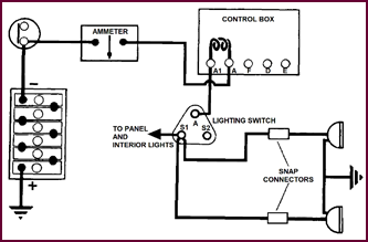 On modern cars, both side lamps are fed in parallel from the S1
terminal of the main lighting switch. (Many of you will remember the earlier
type combined ignition and light-ing switch with this terminal marked 'T'.)
On modern cars, both side lamps are fed in parallel from the S1
terminal of the main lighting switch. (Many of you will remember the earlier
type combined ignition and light-ing switch with this terminal marked 'T'.)
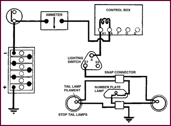
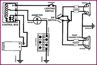
Figure 11. Typical circuit diagram for
side lamps.
You will notice too that the lighting switch
obtains its feed via the LOAD TURNS of the voltage regulator in the con-trol
box. The complete circuit, therefore, would be as follows: From the battery,
usually via an ammeter, to terminal 'A' of the control box, then through
the load winding to 'A1', feeding the lighting switch at terminal 'A'. The
circuit continues across the switch through both bulb filaments to earth, being
completed via the vehicle chas-sis to the battery earth.
Notice particularly the 'Snap Connectors'.
These are of great significance in servicing and troubleshooting work with
which we shall deal later.
It will be found throughout the lighting
circuits that exten-sive use is made of single and multiple snap connectors in
order to reduce the lengths of cables necessary.
Rear Lighting
Circuit
The rear lighting is also fed from the S1
terminal of the main lighting switch. Let us follow the circuit from this
point. A single cable leads direct to a double snap con-nector. Feed cables
branch off to the tail lamp bulb filaments in the stop tail lamps and another
to the number plate lamp.
Earth return cables are looped from all the
lamps to one snap connector and then earthed to the chassis.
Figure 12. Rear lighting circuit.
 Stop Lamp Circuit
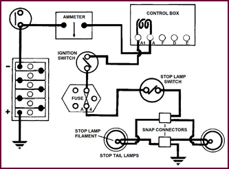
Figure 13. Circuit for stop lamps.
As the stop lamps are usually part of the
tail lamp assem-bly we have included the circuit here. These lamps usually carry
double filament bulbs, one 4 or 6 Watts filament for the rear light and either
an 18, 21 or 24 Watts filament for the stop lights with which we are concerned
in this diagram.
The circuit is simple enough as you can
see. The stop lamp filaments are fed from the A4 fuse via a separate
stop lamp switch actuated by the brake linkage.
Feeding from the A4 circuit means that the
lamps are master controlled by the ignition switch with a fuse in circuit.
In Part 2, on Page 8, we shall consider
lighting which, while not being 'obligatory' in the legal sense, is of paramount
importance to all road users. We shall begin with the main headlamp lighting.
PART TWO: HEADLAMPS
Dazzle
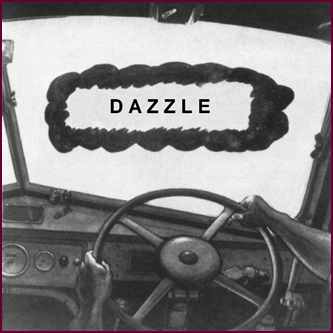 We shall approach the subject of headlamp lighting by
way of the problem it inevitably poses: In so doing, we hope to convey the
sense which lies behind the development of the modern Lucas headlamp unit.
We shall approach the subject of headlamp lighting by
way of the problem it inevitably poses: In so doing, we hope to convey the
sense which lies behind the development of the modern Lucas headlamp unit.
Figure 14. The questions about dazzle.
With headlamps becoming necessarily more
and more powerful as the speed of vehicles increased, a problem arose which, in
recent years, has been causing concern ln all countries where night driving is
widespread.
How do we provide adequate lighting of the
road for fast driving and at the same time use this light when passing oncoming
vehicles so as not to cause discomforting dazzle? What sort of safe compromise can
we strike between poor headlights which scarcely enable the driver to see, and
those which light the way brilliantly, yet blind the approaching driver? For
road safety depends upon both drivers being able to see.
 Dip And Switch Method
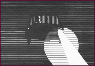
Figure 15. The older dip and switch
method.
The only effective answer at present
appears to be a really efficient dipping system.
The method we show you in Figure 15,
known generally as the 'Dip and Switch Method', has been employed for many years on British vehicles. The off-side
light, that nearest the oncoming driver is switched off, and the other 'dipped'
downwards and directed towards the near-side curb.
The snag in this is obvious enough; the
approaching driver is safeguarded but the driver dipping his lamps is suddenly
left with less than half his road lights. The difference between the main and
dipped light is considerable.
Double Dipping
 The introduction of the Lucas double dipping system over-came this
disadvantage. Both lights remain on, dip filaments in the headlamp bulbs providing
adequate illumination of the road in the dipped position. So good is this
light, that speeds of 40-50 m.p.h. can be maintained with perfect safety.
The introduction of the Lucas double dipping system over-came this
disadvantage. Both lights remain on, dip filaments in the headlamp bulbs providing
adequate illumination of the road in the dipped position. So good is this
light, that speeds of 40-50 m.p.h. can be maintained with perfect safety.
Figure 16. The Lucas double dipping
system.
The use
of pre-focus bulbs and the block pattern lens reduces the dazzle of
the approaching motorist to an absolute minimum.
But perhaps we are going a little too
quickly; some of these terms may need explaining.
 Optical Principles
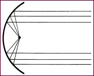
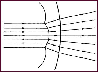
Figure 17. A parallel beam of reflected
light.
For you to appreciate the double dipping
system fully, let us consider for a moment the optical principles involved.
If a pin-point of light were placed at the
exact focus of a parabolic reflector, in theory we should obtain a perfectly
parallel beam of light. No light rays would be reflected above the horizontal.
Pre-Focus Bulb
Arrangement
 But a bulb filament can never be merely a pin-point. It must have a
certain substance to enable it to carry sufficient current and to make it
mechanically strong.
But a bulb filament can never be merely a pin-point. It must have a
certain substance to enable it to carry sufficient current and to make it
mechanically strong.
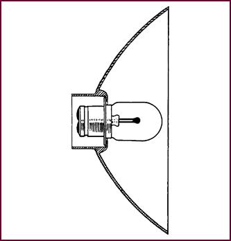
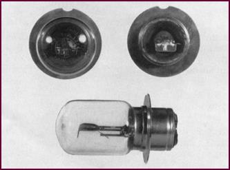
Figure 18. A pre-focus bulb with
locating flange.
Not all the incandescent area of the filament
then can be at the exact focal point of the reflector, although by using what
we call a pre-focus bulb
with a locating flange we can achieve what is, for all practical purposes, an
accurate positioning.
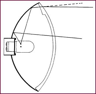
 The Dazzle Rays
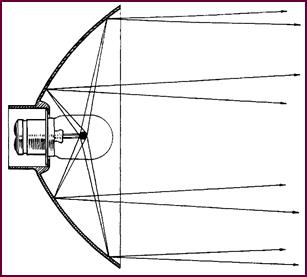
Figure 19.
A diagram showing dazzle rays.
Arising from
what we have just said, the beam produced by such a bulb and reflector
combination must necessarily be slightly divergent; some light rays are
reflected above the horizontal. These are the ones which cause dazzle.
You can see from Figure 19 that it
is not only the rays which strike the lower half of the reflector that are
project-ed upwards; a proportion of the light striking the upper areas is
similarly affected.
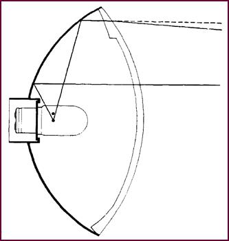
 Dipped Beam Reflection
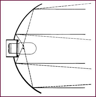
Figure 20. Dipped beam light reflection.
A second or dip filament situated above the filament we have so far
discussed, i.e., displaced from the focus of the reflector, and actually offset
from the axis of the bulb, would produce a 'dipped beam' whose main concentr-ation
would fall below the horizontal.
But this dip filament would still give rise
to some upwards reflected light as you can see by the dotted lines at the top
and bottom of the reflector. Light rays emitted from the filament, striking
these upper and lower areas, will inevitably be reflected above the main
concentration of the beam. This means that no matter how the dipped beam is set
or directed, some light will rise, causing dazzle to the approaching driver.
Dazzle Points
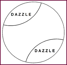
Figure 21. Location of prism groups in
lens.
To re-direct these upwards reflected rays
so that they are projected below the horizontal line, groups of prisms are
moulded into a special glass known as a Block Lens. The dazzle points, where
the two prism groups must be formed, are indicated here.
(You will see
later how the actual positioning varies accord-ing to the lighting regulations
of a particular country.)
 Prismatic Control – Dipped Beam
Figure 22. Prismatic control for dipped
beam.
You can see here what the effect is as far
as the Dip filament is concerned: light rays formerly rising above the
horizontal are now refracted or bent downwards to the horizontal so that they
fall within the main concentration of the dipped beam.
A similar group of prisms is situated in
the lower area of the glass to control the other dazzle-producing rays in the
same way.
 Prismatic Control – Main Beam
Figure 23. Prismatic control for main
beam.
The prisms also control the light rays of
the main beam – i.e. the rays emitted by our first filament at the focus of the
reflector. Light which was previously projected up-wards and wasted is now
brought into the beam, adding to its intensity.
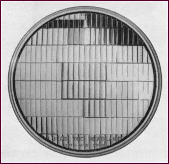
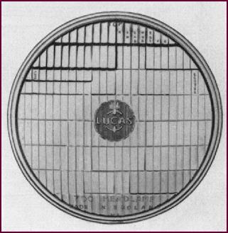 Block Lens
Figure 24. An actual lens with prisms
clearly marked.
Here is a photograph of the actual lens
with the grouping of the prisms clearly marked. They control the rays, then, in
the vertical direction. But what about the horizontal spread of the beam?
This is taken care of by the vertical
flutes moulded into the lens.
 Horizontal
Control
Horizontal
Control
Figure 25. Horizontal control using
flutes in lens.
Here you see the effect of these flutes.
There is sufficient light-spread at good intensity to give enough light for
cornering – the light intensity should be such that it is not the controlling
factor on the speed of cornering.
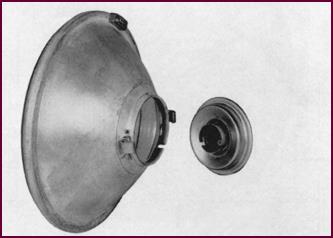
A Lamp Assembly
The moulded lens containing the prism and
flute combin-ation is rolled into a dustproof assembly with the reflector. This
protects the reflector surface, ensuring long life to the light unit.
 The pre-focus bulb is inserted from the
rear of the lamp assembly, thus making replacement possible in service.
The pre-focus bulb is inserted from the
rear of the lamp assembly, thus making replacement possible in service.
Figure 26. A Lucas F700 headlamp
assembly.
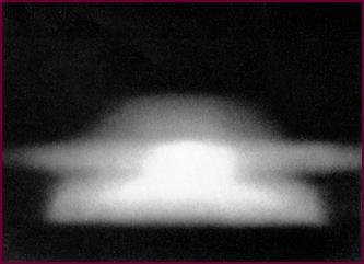
Light Image
This is the pattern of light produced by
the main filament of one block lens light unit. The screen is approximately 25
feet (7·6 metres)from the lamp. Notice the intense spot in the centre of the
beam; this will give a long driving light. There is also good side-spread immediately
in front of the lamp and at a little distance ahead. This ensures safe
illumination of the sides of the road, enabling the driver to position himself
accurately, and to pick out pedestrians and cyclists with ease.
Figure 27. Image on a screen, one
headlamp only.
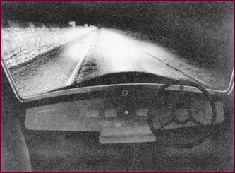
Main Beam
Lighting
This is how the main beam lighting appears
from behind the wheel. The road is illuminated for a length of over 170 yards
(155·5 metres). The brick pillars are 17 yards (15·5 metres) apart and 8 feet
(2·4 metres) high. This will give you an idea too of the 'low top' of the beam.
Figure 28. Light projected with main
beam.
This long range light enables the driver to
see the contour of the road – he can also anticipate any sudden changes in
direction, a realisation which brings with it an added sense of security. The
road a little distance in front of the vehicle is also brightly and evenly lit,
making it possible for the driver to proceed according to the state of the
surface.
This main beam lighting gives sufficient
light straight ahead to enable speeds of up to 55 m.p.h. (88·5 k.p.h.) to be
maintained with safety in average conditions. This limit has been set because
the vast majority of drivers hardly ever exceed this speed, and, as we are
necess-arily working with a limited amount of light, an excess in the centre to
allow faster driving might mean less at the sides of the road.
Dipped Beam
Lighting
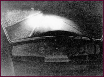 Both head lamps are now dipped, but notice that the light has
relatively not decreased in intensity. These dipped beams provide adequate
light for passing the oncoming vehicle with safety and comfort.
Both head lamps are now dipped, but notice that the light has
relatively not decreased in intensity. These dipped beams provide adequate
light for passing the oncoming vehicle with safety and comfort.
Figure 29. Illustrates dipped beam
illumination of road.
If both headlamps are correctly set, the
approaching driver will be subjected to little or no dazzle.
And here we would like to make two very
important points. In the first place, the approaching driver will of course be
aware of two headlamps. If he happens to glance directly at them he will see
two lights – but they are only sources of light: they do not dazzle. On looking
directly ahead again, there is no sudden, urgent need for re-focusing of the
eyes, no dangerous 'black' period that we experience after the eyes have really
been 'dazzled'.
The other point is this: you will
appreciate that if both vehicles are equipped with block lens light units and
the beams dipped, the whole breadth of the road surface bet-ween the vehicles is
illuminated, without dazzling either of the drivers.
This avoids any possible misjudgement of
the width of the vehicle.
Light Units And
Bulbs – Lens Design
It may be appreciated that the desired
results from double dip lighting will only be obtained if the bulb and light
unit combination is correct.
Both light units and bulbs vary in
accordance with the lighting regulations of different countries.
Broadly speaking, we can divide these into
three distinct groups according to different areas: right-hand drive countries,
left-hand drive, and continental.
The continental sphere has to be
sub-divided, special lighting regulations being in force in France. In order to
meet International Regulations not covered by the stand-ard pattern lens and
also to provide driving lights with special characteristics for racing work, a
number of variations to the standard Block Lens are sometimes fitted. Any of
those illustrated may be found on vehicles from time to time.
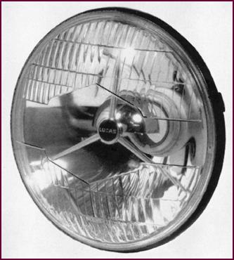
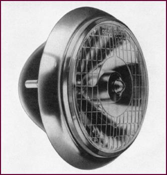
F700 Light Unit
This is the F700 light unit used in right-hand
drive areas. It is the present standard unit fitted by British car man-ufacturers
to vehicles for the home market.
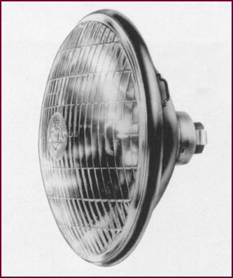 The prism arrangement is suitable for beams dipping to the left.
Figure 30. The Lucas F700 light unit.
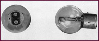
 Correct Bulbs
Figure 31. The Lucas 354 headlamp bulb.
The correct bulb is the 354 for 12-volt
units with a rating of 42/36 Watts (the main filament value is given first, the
dip filament second). The No. 356 bulb, exactly similar in appearance, is used
for 6-volt applications, its Wattage being 45/35 Watts.
Notice that the main filament is axial and
that the dip filament is above it and to the side.
The single slot in the flange precludes the
possibility of incorrect fitting.
 F700 Unit – Left Hand Drive
Figure 32. Lucas F700 for left-hand
drive vehicles.
The F700 unit for left-hand drive
countries, including the U.S.A. has the prism groups moulded into the opposite
side of the lens, i.e. top right and bottom left. Also, the dip filament in the
pre-focus bulb is positioned so as to give deflection of the beam to the right.
The bulb numbers are:
12-volt No. 355 42/36 Watts
6-volt No. 387 45/35 Watts
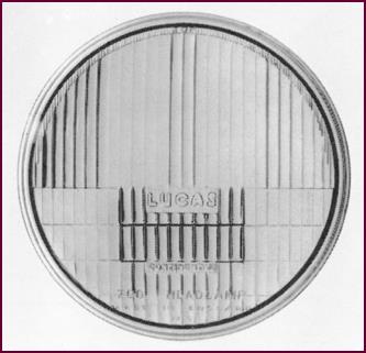 F700 Continental
Figure 33. Lucas F700 for continental
use.
This special F700 block lens light unit has
been designed for use in European countries. The prisms are concen-trated in
the centre of the lower half of the lens, thus giving the necessary vertical
dip.
Bulbs For The
Continent
The correct bulbs for use with the
continental unit are:
12-volt No. 370 45/40 Watts
 6-volt No. 378 45/40 Watts
Figure 34. Bulbs for use in continental
Europe.
Both bulbs are of the pre-focus type but
with a hooded dip filament.
A similar bulb No. 371 with a yellow
envelope, may also be fitted for touring in France.
This is the bulb recommended for any of the
F700 light units when touring the continent.
 Special Unit For France
Figure 35. Special headlamp unit for
France.
Where the visit is of a more permanent
nature, both light units and bulbs must comply with the French regulations.
We show you here a suitable Lucas unit. The
lens used is still the CONTINENTAL F700, but the reflector is fitted with the
special holder to take the three pin bulb legal for France.
 The Three Pin
Bulb
The Three Pin
Bulb
Figure 36. The three-pin bulb for use in
France, where HAUT means TOP, and the bulb GLASS is AMBER.
This bulb, No. 372, has a hooded dip
filament, a yellow glass envelope and three pin fixing. The bulb must be
correctly inserted in the holder and for this reason it is marked 'haut' – 'top'.
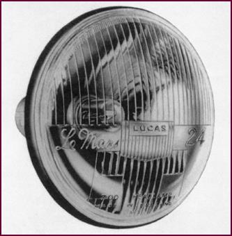 Le Mans Unit
Figure 37. The Lucas Le Mans headlamp
unit.
This 'Le Mans' light unit was specially
designed for fast driving on the continent. Again you will notice the prisms
are in the centre for vertical dipping.
Models of the unit are made to take either
the British pre-focus bulb or the French bulb you've just seen.
P700
A later design block lens, the P700, has a
clear centre, giving a longer beam. This does enable us to drive faster along
the straight, but remember that with a given amount of light we can't increase
the intensity of the beam centre without losing something at the sides.
Notice the hood attached to the centre
piece.
Apart from enhancing the appearance of the
lens, this does of course serve a useful purpose. With the clear glass centre,
some rays are projected upward at about 45°. These rays would tend to produce a slight glare immediately in
front of the vehicle which would affect the driver, particularly in misty
conditions. The driver of an ap-proaching vehicle however would in no way be
troubled. The hood suppresses this tendency to glare.
Figure 38. The Lucas P700 light unit.
Lenses are made for right hand, left hand
and continental application, the positioning of the prisms varying as in the 'F'
range.
The bulbs used in the previous range can
also be fitted to this 'P' range.
The P700 is not permissible at
present in the U.S.A.
 J700
J700
Figure 39. The Lucas J700 light
assembly.
 The last light unit we have to show you is the J700. Again you'll notice the clear centre of the lens and the
hood over the bulb. A lens is produced for both left and right hand drive.
The last light unit we have to show you is the J700. Again you'll notice the clear centre of the lens and the
hood over the bulb. A lens is produced for both left and right hand drive.
The specified bulb is the No. 404, a 12-volt
pre-focus type with a 60 Watts main filament and a 36 Watts dip filament.
This unit is not permissible in the U.S.A.
Focusing And
Tracking
No matter how good the actual head lamps
are, they will never do their job as intended unless they are correctly set.
The two terms usually associated with this process are 'focusing' and 'tracking'.
The latest bulbs, as we have said, are
automatically focused in the reflector by the positioning flange and notches.
Earlier types are usually adjustable in the bulb holder. In such cases, the
focusing adjustment should always be carried out before the alignment or 'tracking'
of the lamps.
Headlamp
Setting
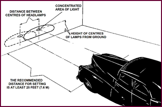 Figure 40 shows one method of setting
lamps. A screen is used, set square to the vehicle and at least 25 feet (7·6
metres) from it. The car should be loaded and standing on level ground. Mark
the lamp height and the distance between the centres on the screen. The setting
operation is eased, as we suggest, by covering one headlamp. Make sure that the
MAIN BEAM lighting is switched on.
Figure 40 shows one method of setting
lamps. A screen is used, set square to the vehicle and at least 25 feet (7·6
metres) from it. The car should be loaded and standing on level ground. Mark
the lamp height and the distance between the centres on the screen. The setting
operation is eased, as we suggest, by covering one headlamp. Make sure that the
MAIN BEAM lighting is switched on.
Figure 40. Placement of vehicle for
headlamp setting.
A. Front of car to be square with screen.
B. Car to be loaded and standing on level ground.
C. Recommended distance for setting, at least 25 feet (7.6 metres).
D. For ease of setting, one
headlamp should be covered.
Then adjust the lamps so that the beams
fall on the screen as we have illustrated.
Notice that just over half of the main concentration of light falls below the horizontal
line.
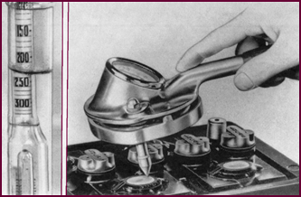
The Beam Setter
This 'Beamsetter' greatly simplifies
headlamp setting.
The apparatus
is first positioned in accordance with the track of the
vehicle wheels by means of a light ray and screen.
Each lamp beam is then directed in turn
through the con-denser lens of the apparatus and the position of maximum light
intensity read off on a candle power scale. The reading is dependent on the
intensity of light falling on a photo-electric cell.
Figure 41. A Lucas Beam-setter to adjust
a headlamp.
Headlamp Wiring
Circuit
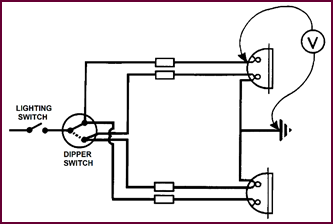
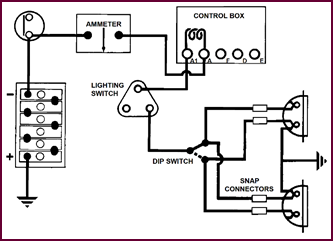 The headlamps are supplied with current from the lighting switch S2
terminal. The latter is connected via a cable to the dip switch, carrying
battery current to either the main or dip filaments in both headlamps, depending
upon the switch position.
The headlamps are supplied with current from the lighting switch S2
terminal. The latter is connected via a cable to the dip switch, carrying
battery current to either the main or dip filaments in both headlamps, depending
upon the switch position.
Figure 42. The headlamp wiring circuit.
Earth leads from each lamp are attached to
any suitable point on the chassis, thus closing the circuit with the battery
earth.
The circuit from the battery to the
lighting switch is the same as for the side and rear lighting, current again
passing via the load turns of the voltage regulator, thus compensating
the headlight load.
 PART THREE: AUXILIARY LIGHTS
Auxiliary
Lighting
Auxiliary lights, such as long-range
driving lamps, fog lamps and reversing lamps are to-day widely fitted by
motorists as 'extras'. But the great majority of the motor-ing public is
rapidly realising that these so-called 'extras' are well-nigh indispensable to
modern motoring.
Such additional lamps afford a convenient
choice of lighting to cope with any possible combination of traffic, weather
and speed.
They bring added safety and comfort to
night driving.
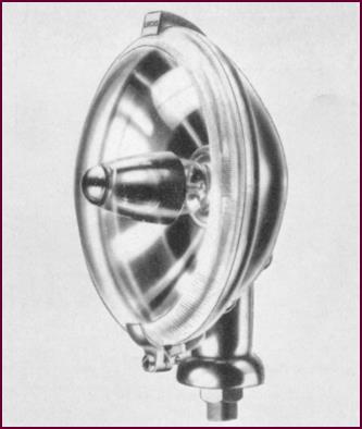
SLR 700
 This long-range driving lamp, the SLR 700, is intended for use in
conjunction with the car's normal headlamps for fast night driving. The
specially designed conical bulb shield and clear lens have the effect of
condensing all the light power into a thin 'pencil' beam of great intensity –
in fact 100,000 candle power are projected in advance of the headlamps a
searching beam which makes fast driving safe.
This long-range driving lamp, the SLR 700, is intended for use in
conjunction with the car's normal headlamps for fast night driving. The
specially designed conical bulb shield and clear lens have the effect of
condensing all the light power into a thin 'pencil' beam of great intensity –
in fact 100,000 candle power are projected in advance of the headlamps a
searching beam which makes fast driving safe.
Figure 43. The Lucas SLR 700 driving
lamp.
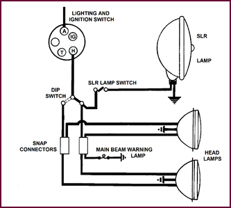
SLR Circuit
The SLR should always be fitted as we show
in this diagram. The feed is taken from the MAIN beam side of the dip switch
and then via a separate switch to the lamp. Thus the SLR is only operative when
the main beams are in use. On dipping the headlights, the lamp is also
extinguished. This of course is done to avoid dazzling an oncoming driver.
Figure 44. The SLR circuit diagram.
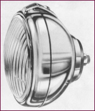
SLR 576
 This SLR 576 is a development of the 700. It is much smaller in size
– less than 6 inches (152 mm) in diameter – but is remarkably efficient,
producing a long, concen-trated driving beam of 80,000 candle power.
This SLR 576 is a development of the 700. It is much smaller in size
– less than 6 inches (152 mm) in diameter – but is remarkably efficient,
producing a long, concen-trated driving beam of 80,000 candle power.
Figure 45. The Lucas SLR 576 driving lamp.
Its size and shallow body make it ideal for
fitting to cars where frontal space is limited.
The 576 should also be fitted so that it is
automatically extinguished when the headlamps are dipped.
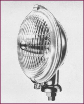
SFT 700
One of our most popular fog lamps, the SFT 700,
incorp-orates the block pattern lens. This lens, in conjunction with the
special reflector, pre-focus bulb and bulb shield, produces a flat-topped beam
with exceptionally wide side-spread and without upward or backward glare. It 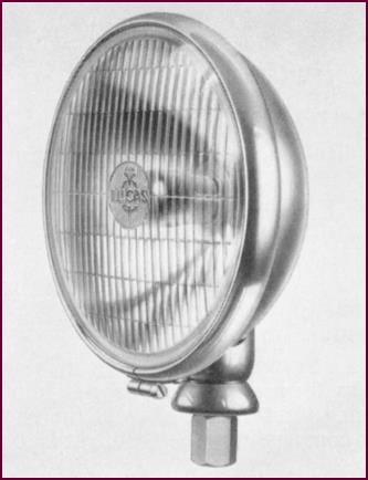 gives an ideal light for driving in fog.
Figure 46. The Lucas SFT 700 Fog lamp.
 462 Range
Figure 47 (below left). The Lucas WFT
462 body-mount fog lamp.
The 462 models are the smallest fog lamps
we make, having a diameter of 5" (127 mm).
They are fitted with the block pattern lens
and produce the characteristic 'flat-topped' beam.
The WFT462 shown here is designed with a
fixing bolt in the back of the lamp, enabling it to be mounted directly on to
the front of the vehicle, or on to a vertical or suspended bracket. The model
in this range with the usual spigot fixing is the FT462.
 SFT576
Figure 48. Lucas SFT 576 fog lamp to
match SLR 576.
Another attractive fog lamp, the SFT576 has
been designed for use with the SLR576 long-range driving lamp. Like the larger
700 fog lamp we've just shown you, it has a wide-spread beam, sharply cut off
at the top – a most effective light in fog.
Fitting presents no difficulties, thanks to
the shallow body and the 6" (152 mm) diameter.
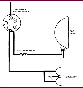
Fog Lamp
Circuit
Fog lamps are normally connected in the side
lamp circuit, either from snap connectors in the feed wire or as we show here
direct from the lighting switch. They are of course also controlled by a
separate switch.
Figure 49. Fog lamp circuit diagram.
494 And 511
Reverse Lamp
 These two auxiliary lamps have been
designed expressly as reversing lights and provide ample illumination to the
rear.
These two auxiliary lamps have been
designed expressly as reversing lights and provide ample illumination to the
rear.
Figure 50. Reverse lamps, left: 494;
right: 511.
The model 494 on the left is roughly oval
in shape and is styled to blend with the tail lines of modern cars. A wide,
even distribution of light is assured by the ribbed cons-truction of the glass.
The mounting is external, by stem and 'ball-joint'
fixing. The other lamp, the 511 model, is suitable for fitting to the majority
of cars – it is only 3½" (89 mm) in diameter and spigot mounted.
The bulb usually fitted in both these lamps
is the No. 221 12-volt 18 Watts or the No. 317 6-volt 18 Watts. The max-imum
permissible bulb rating in Great Britain is 24 Watts.
Reverse Lamp
Circuit
 A reverse lamp should always be fed from the A4 fuse terminal.
Current passes from the battery, through the ammeter and then via the
load turns of the voltage regulator.
A reverse lamp should always be fed from the A4 fuse terminal.
Current passes from the battery, through the ammeter and then via the
load turns of the voltage regulator.
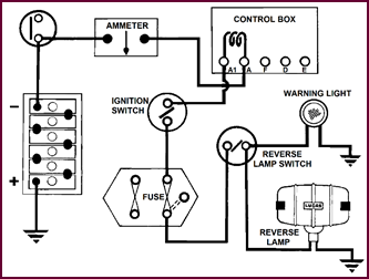 Terminal A1 then feeds the ignition switch. When this is in the 'ON'
position, current passes through the A4 fuse to one side of the reverse lamp
switch, which is normally situated near the gearbox selector mechanism. When
reverse gear is selected, this switch is closed and the reverse light operates.
Terminal A1 then feeds the ignition switch. When this is in the 'ON'
position, current passes through the A4 fuse to one side of the reverse lamp
switch, which is normally situated near the gearbox selector mechanism. When
reverse gear is selected, this switch is closed and the reverse light operates.
Figure 51. Reverse lamp circuit.
Vehicles fitted with a reverse lamp that is
not controlled by the gear change lever must have a warning light in circuit.
This, as you can see, is fed from the lamp side of the reverse lamp switch.
The standard switches most suitable are
models PS7 and PS15. When the 494 or 511 reverse lamps are supplied as
accessory kits, either one or the other of these switches is included.
Lighting
Regulations
We stress once more that Regulations
affecting the British Isles concerning the positioning, dimensions and bulb Wattage
of all lamps are contained in the latest 'Road Transport Lighting Act'.
They specify among other things the height
of the lamps from the ground, the distance from the outer edge of the vehicle,
the dimensions of the glass or lens, the type of glass, the colour of the light,
etc.
It is recommended that these lighting
regulations should be studied in order to understand clearly the correct pos-itioning
of all lights.
PART FOUR:
MAINTENANCE
Maintenance
Points
1. Faulty
Bulbs.
2. Bad
Earths.
3. Bad
Contacts.
4. Faulty Wiring.
Faulty Bulbs
If a bulb filament is broken, make sure
that the fault is due to normal wear and tear and not the result of vibration
caused by a loose lamp fixing or faulty bulb holder.
Don't forget too that in the category 'faulty'
we include bulbs of the incorrect type, unsuitable Wattage and wrong voltage.
When individual lights are poor or out of
action, these points should be checked.
Bad Earths
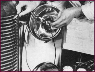
 Bad earths are a frequent cause of poor
lights and even complete failure.
Bad earths are a frequent cause of poor
lights and even complete failure.
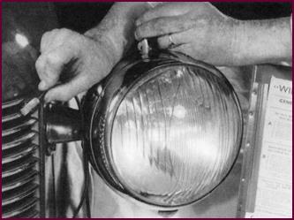
Figure 52. Checking earth between lamp
and car body.
A check should be made with a voltmeter
between the lamp body and a good earth on the vehicle. A voltage reading indicates
a faulty earth. The voltmeter should read zero if the earth connection is good.
 Dirty Contacts
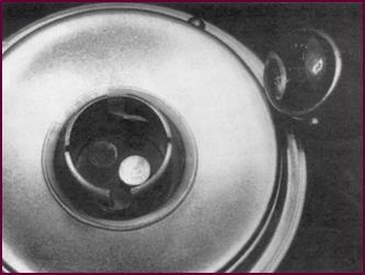
Figure 53 (left, below). Testing for
dirty or loose contacts.
Dirty contacts, either at the bulb holder
or the bulb will always cause trouble. Frequently, contacts are black-ened by
sparking between the holder and bulb contacts, due to a loosely fitting bulb.
What's more, if sparking occurs, the bulb holder springs will overheat and lose
their tension, thus making permanent contact impossible for instance over a
rough road surface.
The only real cure if the bulb holder
contacts are badly blackened or discoloured is to change the holder.
Faulty Wiring
Figure 54 shows
a test being made with a voltmeter to see if there is voltage at the bulb
holder. No voltage reading with the lights switched on indicates a break in the
feed wire.
If this is the case, the circuit should be
checked with a voltmeter at every point in the feed, i.e. control box 'A' and 'A1'
terminals, lighting switch, dip switch and any cable junction, such as a snap
connector. These tests will localise the fault. A broken wire or dirty connection
can then usually be found by eye when the voltage readings have been taken.
Figure 54. Testing for wiring fault.
Light Lift
One of the main troubles associated with
lighting in service is that of 'Light Lift'. This is the term used to express
the rise in the light intensity of the headlamps when the engine speed is
increased quickly.
This fault is of course the exception
rather than the rule, but it is one which in many cases is difficult to remedy.
For this reason we intend to go into it at some length.
Reasons For
Light Lift
The final reason for light lift is a sudden
excess of voltage across the filaments of the headlamp bulbs which inc-reases
the brilliance.
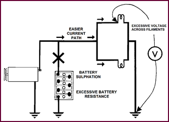
Take the simple case we show you in Figure
??. The battery is sulphated, that is, in a condition where its internal
resistance is comparatively high. The engine is suddenly revved and the dynamo
charges. But the charge will not readily be absorbed by the battery, owing to
its resistance. Instead, the generator voltage will rise directly across the
bulb filaments.
 Admittedly, the voltage rise is limited on modern vehicles by the
regulator, but it is still sufficient to cause light lift, especially when you
consider that with a bad battery the lights will be dim anyway when the engine
is idling.
Admittedly, the voltage rise is limited on modern vehicles by the
regulator, but it is still sufficient to cause light lift, especially when you
consider that with a bad battery the lights will be dim anyway when the engine
is idling.
Figure 55. Reasons for light-lift.
Complete
Circuit
 But the battery is by no means the only cause of light lift. Any
point in the circuit where there is excessive resist-ance will cause a voltage
drop. Consequently, with the engine idling, the lights will not be receiving their
full battery voltage. There will then be a noticeable difference when the
engine is revved and the full generator voltage develops.
But the battery is by no means the only cause of light lift. Any
point in the circuit where there is excessive resist-ance will cause a voltage
drop. Consequently, with the engine idling, the lights will not be receiving their
full battery voltage. There will then be a noticeable difference when the
engine is revved and the full generator voltage develops.
Figure 56. Possible high resistance
points.
In Figure 56 we have indicated many
of these possible high resistance points. You see that they can be any-where in
the circuit; at terminals, at snap connectors and junction points, even in the
wiring itself. There may be one main fault or a combination of minor losses which
all add up to produce light lift.
We have drawn up a test procedure which
will enable you to locate all the more usual faults.
To illustrate this procedure, let us take a
test case. We have a vehicle with light lift, not excessive, but noticeable.
How do we proceed?
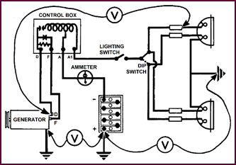
Complete Circuit Divided Into Three Sections
We have divided the vehicle circuit into
three sections:
Lights and switches;
Battery;
 Generator and voltage regulator.
Figure 57. Circuit divided into three
sections.
The first move is to find out just what
light lift we have in terms of volts. The rise in light intensity is visible to
the eye but a reading on a voltmeter gives us a more exact idea of the problem.
A comparative measurement can then also be made at the end of the tests – which
makes sure the fault has in fact been cleared.
 Lights Section Test 1 And 2
Figure 58. Lights section, Tests 1 and
2.
Connect a voltmeter between earth and the
end of the lighting cable as close as possible to the bulb holder. Switch on
the headlights (main beam) and note the read-ing with the engine stationary.
Then make the same test with the engine running at a good charging speed. It is
advisable to carry out these tests at both headlamps, just to make sure that
both are affected by light lift.
Readings on our test vehicle were as
follows:
Engine stationary 11·8-volts.
Engine running 12·8-volts.
Both headlamps gave the same reading. The voltage
difference, then, causing the light lift is 1-volt.
For normal service purposes, 0·5-volt is
considered the maximum permissible reading.
What then, in our case, is causing the
higher reading?
Battery Section
Test 3
 The next point in the procedure is to test the battery to ensure
that no abnormal condition is affecting the circuit as a whole.
The next point in the procedure is to test the battery to ensure
that no abnormal condition is affecting the circuit as a whole.
Figure 59. Test 3, battery section.
We first took S.G. readings of each cell
with a hydrometer and then heavy discharge readings.
Results were as follows:
S.G. Readings:
1·230, 1·230, 1·230,
1·240, 1·240 and 1·230.
Discharge voltage readings over 10 seconds:
1·6-v., 1·5-v., 1·5-v.,
1·6-v., 1·6-v. and 1·6-v.
The battery was obviously in good
condition, and could not be considered as a possible cause of the trouble.
Tests 4, 5 And
6
 Tests 4, 5 and 6 concern the voltage of
the battery.
Tests 4, 5 and 6 concern the voltage of
the battery.
Figure 60. Tests for voltage at the
battery.
First use the voltmeter to check the
terminal voltage with the engine stationary; then with the engine running and
finally with the engine running and full load, (i.e. engine running at charging
speed).
We obtained these figures:
Test 4 12·5-volts
Test 5 13·5-volts
Test 6 12·5-volts
The load we
switched on consisted of a fog lamp and long-range driving light in addition to
the head, side and tail lights.
Test 5
reading should of course be higher than Test 4 for the set to be charging, but
a difference in readings of much above 1-volt would suggest overcharging. In
our case, with 1-volt difference, we felt that a further invest-igation was
necessary – particularly as the battery was reasonably well charged.
Test 6
reading we considered normal – the 1-volt drop from Test 5 showed us that the
load was not too great for the battery. You
see, too great a load on the circuit will cause the battery terminal voltage to
drop to such an extent that when charging begins, light lift will inevitably
result.
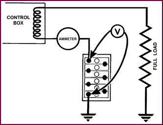
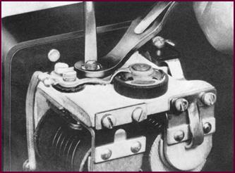
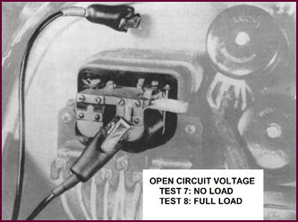 Regulator Open-Circuit
Setting, Tests 7 And 8
Regulator Open-Circuit
Setting, Tests 7 And 8
Figure 61. Open circuit, Tests 7 and 8
at control box.
We further investigated the slightly high
terminal voltage obtained in Test 5 by checking the open circuit voltage of the
regulator. A voltmeter was connected between the regulator frame and earth with
a piece of thin, clean paper inserted between the cut out points.
The reading as we suspected was slightly
high; 16·5-volts instead of between 15·6 to 16·2-volts. The alteration of the
setting was left until the end of the test procedure, to enable us first to
trace any other faults.
We next switched on the full load of head,
side and tail and two auxiliary lights. The engine was revved up to the same
speed as in the previous tests and the voltmeter open circuit reading again
noted: 17·5-volts. Something was obviously wrong: if the regulator is working
correctly the reading with full load will be below the no-load figure. The load
turns should reduce the operational voltage of the regulator when a heavy
discharge current is passing to the lights.
On investigating, we found that the 'A' and
'A1' leads were crossed over at the regulator. This fault too was left until
all the tests had been completed.
Tests 9 And 10
We next removed the paper from the cut out
points and switched off the load. We accelerated the engine to a good charging
speed and, leaving the voltmeter still where it was, read off the closed
circuit voltage.
Under these no-load conditions, the reading
was 14-volts.
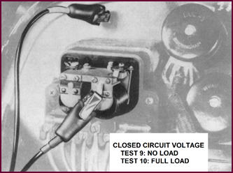 We then switched on the same full load as before and noted the reading:
13·8 volts.
We then switched on the same full load as before and noted the reading:
13·8 volts.
Figure 62. Closed circuit, Tests 9 and
10.
This indicated that the generator was
maintaining its closed circuit voltage under load – stated more simply, the
generator was able to supply sufficient output to bal-ance all the lighting we
had switched on.
It would not have been able to do this for
instance if the driving belt had been slipping. If such a fault does occur the
battery gradually becomes discharged. The lights when idling are less brilliant
and light lift becomes notice-able when accelerating.
Tests 11 And 12
We returned then to the headlamps
themselves, to make two tests at the cable ends. Both headlamp bulbs were taken
out and the lighting switch moved to the 'head' position (main beam). The
voltage in the holder was measured with the engine stationary.
Figure 63. Tests 11 and 12, at the
headlamps.
At the same time, the contacts were
inspected for dirt, as this would prevent the full battery voltage from being
app-lied to the bulbs, causing voltage drop and hence light lift.
We next inserted the bulbs and took two
more voltage readings, as close as possible to the bulb contacts – in our case
at the nearest snap connector.
The reading without bulbs was 12·3-volts
and with the bulbs lit 11·8-volts.
This was a normal drop for the correct Wattage
bulbs – and this is a point we would like to stress: make sure the bulb wattage
is not excessive, i.e. that specified bulbs are fitted. Bulbs with excessive Wattage
can easily cause light lift.
Tests 13 And
14, Complete Circuit
 The final tests we made checked the wiring for voltage losses due to
high resistance connections, lengths of cable of insufficient section to carry
the current, bad earths, etc.
The final tests we made checked the wiring for voltage losses due to
high resistance connections, lengths of cable of insufficient section to carry
the current, bad earths, etc.
Figure 64. Tests 13 and 14, on the
complete circuit.
We tested the insulated line first, with a
voltmeter bet-ween the generator 'D' terminal and the cable ends at the
headlights – with the lighting load switched on and the engine running.
Our reading was exactly 0·5-volt, which we
consider the maximum permissible voltage loss on the insulated line.
If the reading had been higher we should
have had to test with the voltmeter across every connection in the line to
locate the loss.
Two tests were necessary on the earth side,
the first between the generator earth, that is, the body of the machine, and
the battery earth post. Then from battery earth to the headlamp earth – the lights
were still on in each case.
No voltage drop was recorded on our meter, proving
that the earth connections were sound.
Again 0·5-volt loss is the maximum allowed.
Open Circuit
Setting Adjustment
Having checked the complete circuit, we
corrected the faults we had found.
The regulator open-circuit setting was
dropped to a mean figure of 16·0-volts and the light lift again measured as at
the beginning of the procedure.
The readings were 11·75-volts with the
engine stationary; and 12·5-volts with the engine running. This worked out at 0·75-volt
difference, which meant that we had slightly reduced the voltage rise causing the
light lift.
 Open Circuit Setting Adjustment (Continued)
Figure 65. Open circuit setting
adjustment at control box.
Reconnecting
The 'A' And 'A1' Leads
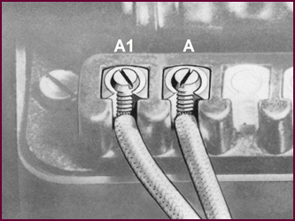 We then changed over the 'A' and 'A1' leads, connecting them
correctly at the control box.
We then changed over the 'A' and 'A1' leads, connecting them
correctly at the control box.
Figure 66. Re-connecting the 'A1' and
'A' leads at the control box.
This had an appreciable effect. The
difference in volt-meter readings was now only 0·25-volt, with the engine
idling in the one case and revving hard in the other.
In a darkened room, the difference in the
light intensity was hardly noticeable, quite within normal limits.
Summary Of
Tests
This summary will give you an overall
picture of the test procedure. It can be shortened with experience – for instance
if a fault is found early on, rectify it and check the result.
But carrying out the whole procedure in
this logical order will test the vehicle completely, ensuring that no fault is
overlooked.
TEST PROCEDURE
– LIGHT LIFT
Voltage At Cable Ends, With Bulbs:
1. Engine Stationary
2. Engine Running
3. Test Battery – S.G and H.R.D. Tests
Battery Terminal Voltage:
4. Engine Stationary –
5. Engine Running –
6. Engine Running Plus Full Load –
Regulator O/C Voltage:
7. No Load –
8. Full Load –
Closed Circuit Voltage:
9. No Load –
10. Full Load –
Voltage At Cable Ends, Engine
Stationary:
11. Without Bulbs –
12. With Bulbs –
Voltage Drop Tests, Engine Running:
13. Insulated Line –
14. Earth Line –
Tests 1 and 2
Should be repeated after each fault correction.
Document
Restorer's Note
Once again, the course session stresses
the requirement for good earthing contacts. This is particularly so when
carrying out the recommended tests.
Observe Domestic Science notions – keep
earth contacts clean and soundly tight.
Mike
Allfrey.
Jowett
Car Club of Australia Inc.