PART 1. WIRING
PRINCIPLES
Simple
Electrical Circuit
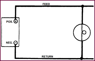 The typical electrical circuit as we know it comprises any
component, such as a lamp for example, connected to a supply – which may be a
battery – by two wires or cables; a feed wire and a return. Any electrical
installation em-ploying this arrangement is known as an insulated return
system, and for some time the electrical equipment on vehicles followed this principle.
The typical electrical circuit as we know it comprises any
component, such as a lamp for example, connected to a supply – which may be a
battery – by two wires or cables; a feed wire and a return. Any electrical
installation em-ploying this arrangement is known as an insulated return
system, and for some time the electrical equipment on vehicles followed this principle.
Figure
1. Insulated Return System.
Earth System
An alternative
arrangement suitable for many applications, uses an
insulated cable as a feed wire to the component, the return being obtained via
earth, which on a vehicle is of course the steel chassis.
Such an arrangement reduces both the amount
of cable necessary and the complexity of the wiring circuits.
This single pole or earth return system
soon became standard practice for vehicle work in general. But for many of the
larger vehicles such as passenger-carrying and certain heavy commercials, which
include petrol carrying vehicles, the
insulated return system is still used.
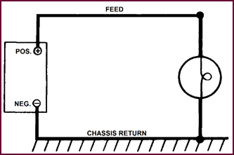 Negative Earth System
Figure
2. Negative Earth System.
With the earth return system the orthodox
arrangement was to earth the negative pole of the supply, and this became known
as the single pole negative earth system, which was used for vehicle work for
several years – on British vehicles up to about 1936.
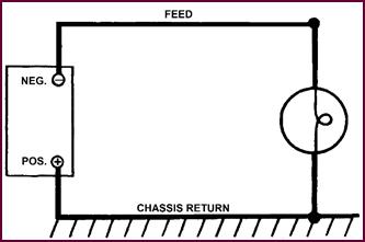 Positive Earth System
Figure
3. Positive Earth System.
It was then found that certain specific
advantages were obtained by earthing the positive pole of the battery instead
of the negative. Thus we had the introduction of the positive earth system,
which is almost universally used today, except for those specialised vehicles
previously mentioned.
One of the main advantages gained by
earthing the positive side of the supply is that the polarity of the spark plug
central electrode is made negative, which results in improved spark plug
performance and longer service life of the spark plugs and the H.T. cables.
At the battery itself the formation of
electrolytic sulph-ation at the positive lug is reduced, and also the marked
tendency to electrical leakage from the cells to earth, the result of the
presence of acidulated moisture. The corrosion effects at switch contacts, cable
connectors, soldered joints, etc. are also reduced, especially under conditions
of excessive humidity.
 Connecting Up And Terminal Markings
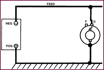
Figure
4. Positive Earth Return.
A point to be remembered is that this
reversal of polarity makes no difference whatsoever to the working of the
system or testing for faults, but it has to be borne in mind when fitting the
batteries and connecting up cables. 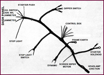 Terminals are all properly marked without reference to the polarity,
as shown in our picture, i.e. the dynamo and field terminals D and F. (The D
terminal being the larger of the two).
Terminals are all properly marked without reference to the polarity,
as shown in our picture, i.e. the dynamo and field terminals D and F. (The D
terminal being the larger of the two).
 Methods Of Wiring
Figure
5. Cables Grouped and Braided.
Now we come to the cables and the method of
wiring which is generally by means of a harness. We shall confine ourselves to
British vehicles, although most others follow the same general pattern. Our picture
shows a wiring loom in course of manufacture.
Multi-coloured cables are employed as a
means of facilitating assembly both at the electrical manufacturer’s works, and
also on the vehicle makers’ assembly lines.
Next, the cables are grouped together and
braided into looms with individual conductors emerging where required, thus
forming main, branch and trunk cables.
The development of this arrangement not
only facilitates assembly but also provides considerable protection against
chafing on metal edges and subsequent wiring faults in service.
Additionally, sub-assemblies such as the
complete car body, or say a steering column may be fully assembled and wired
before being positioned on the vehicle. To facilitate the fitting-up, various
junction boxes and snap connectors are now widely used.
Cable Loom
On some vehicles one complete wiring loom
may be used; on others as many as four separate looms – one main and two or
three subsidiaries are needed and these are finally connected up to the main
loom by means of snap connectors or junction boxes. Altogether there is a vast
variety of wiring looms made up for different makes and models.
So, unless the vehicle is specially laid out,
the stocking and general use of wiring looms is not practicable. For this
reason the renewal of damaged wiring is more easily and economically handled in
service by putting in single cables and employing either junction boxes or snap
connectors to re-join to the undamaged parts of the existing loom.
Figure
6. A Completed Loom.
Junction Boxes
And Cable Connections
For general purposes, a range of junction
boxes and cable connectors is freely available.
The snap or spring connectors shown,
greatly facilitate re-wiring and general service work. They are made in
numerous combinations.
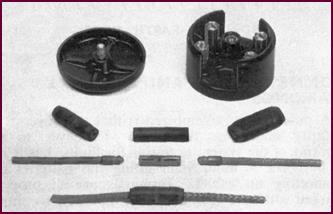 These spring connectors must be borne in mind when fault finding.
Figure
7. Lucas Junction Box and Wiring Connectors.
Types Of Cable
In Use
Now before
going into circuits and colour schemes, let us examine the
types of cables which should be available before embarking on any vehicle
wiring repair work.
They fall into three groups :
1. Starter cables, of which there are three sizes.
2. Car wiring cables, of which there are four popular sizes and as
many colours as can be conveniently stocked by the average motor trader.
3. Ignition cables which are
subdivided into two types:
a) High tension cable, i.e. for spark plugs, etc.
b) Low tension cable, for primary, or low voltage circuits.
Starter Cables
1. The most generally used pattern is a fairly light type of jute
covered cable as shown. This comprises 37 strands of No . 20 SWG (Standard Wire
Gauge) tinned copper wire.
 It is suitable for most light vehicle work where the starter motor current does not exceed 400 amperes.
Figure 8. Examples of Starter Cables
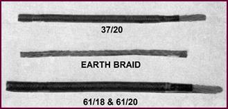
2. Used in conjunction with this is a similar size earth braid which
should always be fitted between engine and chassis as a bonding strip when
rubber engine mountings are used.
This standard braid is also suitable for use as the earth lead
from the positive terminal of the battery to the earth connection on the
scuttle or chassis.
3. The two heavier starter cables are of similar con-struction to
the light one, i.e. jute covered, but have 61 strands of No. 20 or 18 SWG, and
are used for starter currents up to 700 amps.
Where this size cable is used for the starter supply, further
lengths should be made up as a bonding strip and also as the battery earthing
lead.
Circuit Wiring
Cables
Next we come to the cables necessary for
general wiring on the vehicle.
These are all special cables for the work,
and comprise a number of copper strands in rubber and fabric sheaths, specially
treated to be highly resistant to petrol, water and oil. Such cables are freely
available on the market as auto-cable.
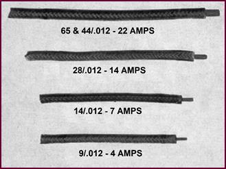
There are five sizes of cable altogether in
general use on the 12-volt system, but for most purposes three are com-monly
used. These are:
1. The battery feed circuit cable, comprising 44 strands of 0·012
copper, generally described as 44/012. This cable has a current carrying
capacity of approximately 22 amperes.
2. Main generator or headlamp circuit cables, com-prising 28
strands of 0·012 copper (28/012) with a current carrying capacity of 14 amperes.
For most purposes this is adequate.
3. Side and tail lamp wiring, accessory, ignition and generator field circuits comprising 14 strands of
0·012 copper (14/012) with a current carrying capacity of 7 amperes.
4. For panel lamp wiring and other incidentals a cable comprising 9 strands of 0·012 copper (9/012)
is the most convenient size.
It should be realised that this is only a
general guide to the cables used in the different circuits. New vehicles with
Lucas wiring are carefully studied to determine the correct cable sizes. Where
long lengths of cable are used, a larger gauge wire may be necessary to prevent
excessive voltage drop.
Figure 9. Examples of Circuit Wiring
Cables. All of these would be colour coded in the Lucas system.
For example, a vehicle with an
exceptionally long cable run for the battery feed, six feet or more may be installed
with an oversize cable, such as 65/012. If at any time this cable has to be
renewed, a similar size replacement should be installed. This last ruling also
applies to re-wiring on vehicles equipped with the 6-volt system, particularly
if voltage drop trouble is encountered.
Equivalent Cables – Current Carrying Capacity
It may be useful to examine how the cable
sizes which have been given, compare with similar cables identified by other
standards of measurement. Some cable man-ufacturers describe their cables in
terms of standard wire gauge and this illustration shows the equivalent sizes
which will carry the same amount of current.
For example: Our 44/012 will compare with
44 strands of 30 SWG wire or 100 strands of No. 36 SWG, all having the same
cross sectional area of copper which deter-mines the amount of current which
can be carried with a specified minimum voltage loss, i.e. voltage drop.
Car Type Cables
9/·012 (30 SWG) EQUIV. 23/36
14/·012 (30 SWG) EQUIV. 40/36
28/·012 (30 SWG) EQUIV. 70/36
44/·012 (30 SWG) EQUIV. 100/36
Ignition Cables
1. The 7 mm high tension rubber cable is generally used for spark
plugs and distributor or magneto leads.
There are numerous grades of this widely used cable at varying
prices, but it is always good policy to buy high quality in order to obtain
maximum durability in service. This avoids failures as a result of
deterioration and cracking, which may cause elusive and annoying misfiring or,
perhaps, complete breakdown.
The top three cables shown in the illustration are Lucas H.T.
cables which all use Neoprene outer casings. This material has proved to be the
best possible protection against heat, oil,
petrol and water.
2. The 4 and 5 m/m low tension cables, which will carry up to about
7 amperes, are widely used for motor cycle work and are equally suitable for
any exposed working conditions, where the cable is not subjected to oil or
petrol.
We have mentioned altogether ten cables,
commencing at the heavy type starter cable carrying up to 700 amp-eres, and
finishing with the 4 and 5 mm mainly used on motor cycles. These ten different sized
cables, together with earth braid, constitute the minimum range which should be
stocked for general motor work.
The Wiring
Circuits
Whilst a car wiring layout as a whole may
appear com-plicated at first sight, the complete arrangement may be broken down
into separate circuits as follows:
1. Battery
and Starter Circuits.
2. The
Ignition Circuit.
3. The
Charging Circuit.
4. Lighting
Circuits.
5. Accessories Circuit.
Circuit
Identification – Battery, Ignition And Charging
To distinguish these circuits, a
distinctive colour scheme is used. The value of such a colour scheme on the car
assembly line is obvious, and, once it is understood, it is of equal value in
service fault finding. So before we discuss all the wiring circuits we must
know about the colours employed.
Eight basic colours are used as follows,
with an approp-riate coloured tracer.
1. Plain, brown cable or brown with coloured tracer in
it, is used as the current supply or feed wire to all services.
2. White for the ignition circuit, and all component feeds
which are essential when the ignition is switched on.
3. Yellow or yellow with coloured tracer is used for
the generator and field circuit.
Circuit Identification – Lighting And
Accessories
4. Red for the side and tail lamp circuits, starting from
the lighting switch.
5. Blue for the headlamp lighting circuit, also starting from
the lighting switch.
6. Purple is used for the auxiliary circuits which are fed
from the ammeter and protected by a fuse A2.
7. Green is used for the auxiliary circuits which are fed through the ignition switch and protected by a fuse,
A4.
8. Black is used for the earth circuit. That is, if a com-ponent
is not fixed directly to the chassis, a cable must be taken to a good earthing
point on the chassis, and this cable will always be black.
The Typical
Wiring Circuit
We can now deal with the wiring circuits as
applied to modern (circa 1952) vehicles.
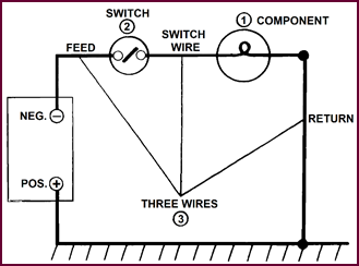 Generally, the electrical system of a motor vehicle can be
considered as a series of simple circuits, each con-sisting of the component (Item
1), its switch, (Item 2), and three wires, comprising the feed,
switch wire and return (Item 3), this return being provided by the frame
of the vehicle, although, in the case of components insulated from the chassis,
an earthing lead is also necessary.
Generally, the electrical system of a motor vehicle can be
considered as a series of simple circuits, each con-sisting of the component (Item
1), its switch, (Item 2), and three wires, comprising the feed,
switch wire and return (Item 3), this return being provided by the frame
of the vehicle, although, in the case of components insulated from the chassis,
an earthing lead is also necessary.
Figure 10. A typical wiring circuit
diagram
Some variations are to be found, such as
fuses, two-way switching and so on, but the principle of feed wire, switch wire
and return remains, and it is upon this that the Lucas wiring colour scheme is
based.
Feed wires carry braiding of a main colour
only. Switch wires have the main colour of feed with a coloured tracer woven
spirally into the braiding. The return or earthing leads are black.
The Standard
Wiring Diagram
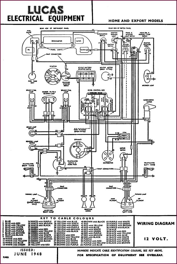
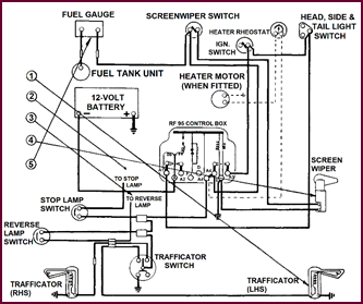
Here we have a typical wiring diagram of
which there is one published for most models and makes of vehicles. These
diagrams are of considerable value in service, but a certain amount of difficulty
may be experienced by the non-specialist in following them out.
It is however, quite simple if each component
circuit is considered individually. which we shall proceed to do, commencing
with the starter system.
Figure 11. A typical motor vehicle’s
wiring diagram is shown on Page 8.

Key To Cable
Colours
1. Blue 2. Blue
with Red
3. Blue
with Yellow 4. Blue with White
5. Blue
with Green 6. Blue with Purple
7. Blue
with Brown 8. Blue with Black
9. White 10. White
with Red
11. White
with Yellow 12. White with Blue
13. White
with Green 14. White with Purple
15. White
with Brown 16. White with Black
17. Green 18. Green
with Red
19. Green
with Yellow 20. Green with Blue
21. Green
with White 22. Green with Purple
23. Green
with Brown 24. Green with Black
25. Yellow 26. Yellow
with Red
27. Yellow
with Blue 28. Yellow with White
29. Yellow
with Green 30. Yellow with Purple
31. Yellow
with Brown 32. Yellow with Black
33. Brown 34. Brown
with Red
35. Brown
with Yellow 36. Brown with Blue
37. Brown
with White 38. Brown with Green
39. Brown
with Purple 40. Brown with Black
41. Red 42. Red
with Yellow
43. Red
with Blue 44. Red with White
45. Red
with Green 46. Red with Purple
47. Red
with Brown 48. Red with Black
49. Purple 50. Purple
with Red
51. Purple
with Yellow 52. Purple with Blue
53. Purple
with White 54. Purple with Green
55. Purple
with Brown 56. Purple with Black
57. Black 58. Black
with Red
59. Black
with Yellow 60. Black with Blue
61. Black
with White 62. Black with Green
63. Black with Purple 64. Black with Brown
PART 2. INDIVIDUAL WIRING CIRCUITS
 Common Battery Supply Circuit
Figure 12. The common battery supply
circuit.
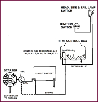
The current supply for all circuits on the
vehicle com-mences either direct from the battery negative terminal, or from
the battery side of the starter switch.
It comprises a heavy brown cable,
first running from the battery to the control box ‘A’ terminal, and through the
load windings of the regulator to the terminal ‘A1’. From here a brown with
blue cable leads to the lighting switch where it loops off to one side
of the ignition switch (terminal ‘A’).
If an ammeter is installed, it will be
placed in the brown lead between the
source of supply and the control box ‘A’ terminal, the cable becoming brown
with white between the ammeter and the control box.
The Starter
Circuit – With Manual Switch
 The first and most elementary circuit is that of the starter motor
system. This motor can be either manually or solenoid operated.
The first and most elementary circuit is that of the starter motor
system. This motor can be either manually or solenoid operated.
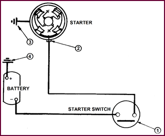
Figure 13. Starter circuit with manual
switch.
Our picture shows the manually operated
starter motor circuit. The current path is from the negative terminal on the
battery to the starter switch (Item 1), across the switch contacts to
the insulated terminal on the starter motor (Item 2), through the
starter to the engine block, then via the braiding strip to the chassis (Item
3), returning to the positive terminal of the battery via the
battery earth cable (Item 4).
The earth cables 3 and 4 are most important
to the suc-cessful operation of the starter, particularly under cold starting
conditions and must always be well maintained.
Where a solenoid starter switch is fitted,
an additional relay circuit is introduced.
The Starter Circuit – Solenoid (Relay) Operated
In this arrangement of the main starter
circuit we have to add a solenoid operating circuit, and this is under the
control of the ignition switch. That is, the starter solenoid can only be
operated with the ignition switched on.
Firstly, there is the common supply from
the battery to the ignition switch for all the circuits.
Our solenoid supply is taken from the other
side of the ignition switch (A3) to the solenoid operating push by a white
cable, and from this push to the solenoid winding by a white with red
cable. The winding is earthed to the casing of the solenoid itself, thus
completing the earth 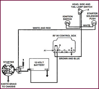 side of the circuit back to the battery earth.
Figure 14. The starter circuit with
solenoid operation.
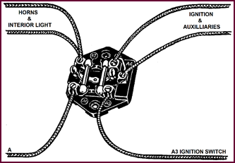
The Ignition
L.T. Circuit
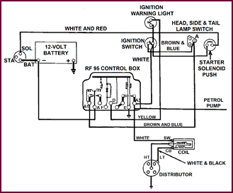 A white cable, commencing at the A3 terminal of the ignition
switch is taken to the A3 terminal at the control box, and provides a common
supply for the ignition units (coil and distributor) together with all the
ignition acces-sories – fused and unfused – which are under the control of the
ignition switch.
A white cable, commencing at the A3 terminal of the ignition
switch is taken to the A3 terminal at the control box, and provides a common
supply for the ignition units (coil and distributor) together with all the
ignition acces-sories – fused and unfused – which are under the control of the
ignition switch.
Figure 15. Wiring diagram of ignition
L.T. circuit.
Using the A3 terminal on the control box as
a junction point, a white (28/012) cable connects directly to the SW
terminal of the ignition coil. A white with black cable joins the
CB terminal of the ignition coil to the L.T. terminal of the distributor.
The unfused accessories such as the petrol
pump and automatic choke will also be supplied from the A3 control box terminal
using the white cable as the feed wire.
The ignition warning light feed wire, also
a white cable is taken direct from the A3 terminal of the ignition
switch.
The Charging
Circuit
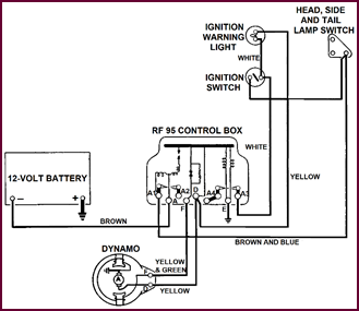 The main components involved in the charging system are the
generator, control box and battery.
The main components involved in the charging system are the
generator, control box and battery.
Figure 16. Diagram of a typical charging
circuit.
That part of the circuit connecting the
battery with the control box has already been dealt with as the brown
battery supply circuit.
The generator circuit itself consists of a yellow
(28/012) cable from generator ‘D’ terminal to control box ‘D’, and a yellow
with green (14/012) from generator ‘F’ terminal to control box ‘F’. Additionally,
there is a yellow (I4/012) cable connecting from control box ‘D’ to one
side of the ignition warning lamp.
The Ignition
Warning Lamp
This indicator lamp performs two functions:
1. It indicates that the battery current is switched on to the
ignition and ignition-fed accessories.
2. It indicates that the generator is charging when the engine is
turning at charging speed.
Follow the previous circuit through.
Commencing at the A3 terminal of the ignition switch, an extension of the white
lead is carried to one side of the warning light. From the other side, a yellow
lead is taken direct to the ‘D’ terminal at the control box.
When the ignition switch is closed, current
feeds from terminal A3 at the switch, through the warning lamp to the ‘D’
terminal of the generator, the circuit being com-pleted through the generator
winding to earth. The lamp therefore, lights up.
When the engine is started, and the
generator voltage builds up to 12-volts, it opposes and equalises the battery
voltage previously applied to the lamp, and no current will flow through it.
The light goes out, and remains so, until the generator ceases to charge, and
its voltage falls. Battery current will then pass through the lamp again and it
will remain alight until the ignition switch is moved to the ‘off’ position.
Sidelamp
Circuit
This picture features the sidelamp circuit.
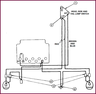 Commencing at the lighting switch terminal S1 (Item 2), a separate
red cable runs to each side lamp via a snap connector (Item 3).
Commencing at the lighting switch terminal S1 (Item 2), a separate
red cable runs to each side lamp via a snap connector (Item 3).
Figure 17. Sidelamp wiring diagram.
The return cable is black and you
will notice that, in this case, it is a full return through snap connectors (Items
4) to a special earthing terminal on the chassis (Item 5).
This was evidently required on this
particular model to assure a good return
path, and it would be very necessary to check this if any trouble were
experienced with the sidelamps.
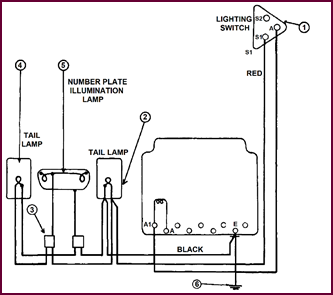 Rear Illumination
Figure 18.
Wiring diagram for rear illumination.
In this example the rear illumination
comprises tail lamp, one on each side, and also the number plate box lighting
comprising two bulbs.
Commencing at the S1 terminal on the
lighting switch (Item 1) from which the side lamp feeds are also con-nected,
another red cable runs directly to the first tail lamp (Item 2).
This red cable ‘loops’ out again to a snap connector located in the
luggage boot (Item 3). From this snap connector, two more red cables
feed the second tail lamp (Item 4) and the two bulbs wired in parallel
in the number plate box (Item 5).
You will notice particularly that a black
earth wire con-nects from both tail lamps and the number plate box, to the
earth terminal on the control box, and thence to the chassis earth (Item 6).
The Head Light
Circuit
We have already explained that all the main
current passes over the load-turns on the voltage regulator to the lighting
switch.
 So we can commence at the S2 terminal on the lighting switch (Item
1).
So we can commence at the S2 terminal on the lighting switch (Item
1).
Figure 19. Wiring diagram for headlamps
circuit.
From this point, a blue cable runs
via a snap connector (Item 2) direct to the foot dipper switch (Item
3).
The dipper switch is a two way switch. From
one terminal two blue with white cables connect through snap con-nectors
(Item 4) to the main filament in each headlamp bulb (Item 5).
From the other terminal on the two way
switch, two blue with red cables run through snap connectors (Item
6) to the dip filament in each headlamp bulb.
Here again, separate black earth
cables are fitted to ensure a good return path for the lamps. These earth
cables connect direct from the bulb-holders in the lamp, via the control
box earth terminal, to the common earth point on the chassis.
The Instrument
Panel Lighting
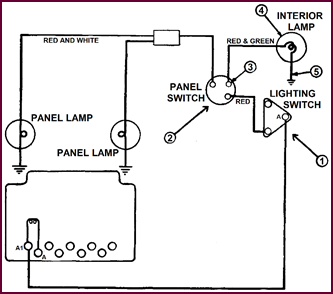 The last item is the lighting on the instrument panel.
Figure 20.
Wiring diagram for instrument panel lighting.
This is generally fed from the sidelamp
terminal on the lighting switch.
On this model a red feed cable,
commencing from the lighting switch (Item 1), supplies the panel switch
(Item 2), and this loops as a red with white cable to a
snap connector and the individual panel lights. In this case there is no
separate earth cable.
From the panel switch (Item 2),
there is a red with green cable (Item 3), which feeds the
interior lamp (Item 4), and also an earth cable (Item 5), which
is a cable direct from the lights to the chassis.
Notice that the interior light is wired
directly to the panel light switch, but, generally, interior lights are fused,
taking their supply from the A2 fuse.
The Complete
Lighting Circuit
Figure 21. Diagram of the complete
lighting circuit.
Here we have the wiring diagram of the
complete lighting installation; we have seen just how simple this is by
breaking it up into individual circuits.
The Long Range
Driving Lamp
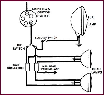 The most satisfactory arrangement for installing this lamp is such
that when the head lights are dipped the SLR lamp should automatically go out,
thus avoiding the necessity for two separate operations.
The most satisfactory arrangement for installing this lamp is such
that when the head lights are dipped the SLR lamp should automatically go out,
thus avoiding the necessity for two separate operations.
Figure 22. Wiring diagram for installing
a long range driving lamp.
This result can be conveniently obtained by
taking a red with blue (28/012) cable direct from the main beam
terminal of the dipper switch.
An additional hand control switch may then
be inserted in this feed line to enable the driver to have the SLR on with his
head lamps on main beam. With this arrange-ment the lamp will immediately go
out when the head lights are dipped.
Fog And Pass
Lamps
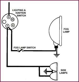 When fitted as initial equipment, fog and pass lamps will usually
take their current supply from the ‘S’ or ‘T’ terminals on the lighting switch
so that they may be auto-matically switched off with the side lamps. If such
lamps are fitted subsequently, this is still
the most suitable method.
When fitted as initial equipment, fog and pass lamps will usually
take their current supply from the ‘S’ or ‘T’ terminals on the lighting switch
so that they may be auto-matically switched off with the side lamps. If such
lamps are fitted subsequently, this is still
the most suitable method.
Figure 23. Wiring diagram for fog or
pass lamp.
It is usual to wire these lamps by means of
a red (28/012) cable from the lighting switch to the lamp switch, and
follow with a red with yellow (28/012) to the lamp itself, making
quite sure that the lamp has a good earth. If there is any doubt about this, a separate
black earth wire should be installed. The relatively large size of cable
is necessary if full brilliance from the lamp is to be assured.
Auxiliaries
There are three groups of auxiliaries and
accessories, which take their current supply from either the ‘A3’, ‘A4’,
or ‘A2’ terminals on the control box.
Those supplied from the ‘A3’ and ‘A4’
terminals are under the master control of the ignition switch. Since they are
only required when the engine or vehicle is in motion, this practice precludes
the possibility of their being accidentally left on, and so running the battery
down.
The unfused components
supplied from the A3 terminal will comprise the electric petrol pump, auto choke,
petrol reserve solenoids etc.
The fused components supplied
from the A4 terminal consist of trafficators, stop lamp, reverse lamp, wind-screen
wiper, fuel tank unit, demister and heater motors when fitted.
The A2 terminal and its fuse takes current
direct from the battery through the load windings of the regulator
and is used for interior lights, door lights, low current horns.
The heavy-current horns, such as the
wind-tone models, and also radio sets will preferably have separate fuses, the
initial supply being taken from the ‘A’ terminal of the control box, that is,
directly from the battery and not through the load windings of the regulator.
There remain a few additional items, which,
for special reasons, may take current direct from the battery. Two popular ones
will be the cigar lighter, which takes a very heavy current and the inspection lamp
sockets, which may be required when everything else is off.
We shall now examine all these auxiliary
circuits individ-ually commencing with the ‘A4’ fused auxiliaries under the
control of the ignition switch.
Fused Auxiliary
Circuits On A4
 Now let us examine these A4 circuits on an actual vehicle. They are
the most complicated of any, and we shall consider each one separately.
Now let us examine these A4 circuits on an actual vehicle. They are
the most complicated of any, and we shall consider each one separately.
Figure 24. The ‘A4’ circuit and
components.
As this picture shows, there are only five
altogether on this particular model, i.e.:
1. Trafficators.
2. Stop Lamp.
3. Reverse Lamp.
4. Windscreen Wiper.
5. Fuel Tank Unit.
The Trafficator
Circuit (Refer To Figure 25)
Trafficators are supplied from the A4 (Item
1), 35 amp fuse, local control being provided either by a self-cancelling
two-way and off switch on the steering column, or alternatively by a similar
type of switch on the panel. The most usual ‘run’ of this circuit is as
follows:
A green cable (14/012) from A4 on the
control box feeds to a twin spring connector (Item 2).
Two leads branch from this connector, one
to the stop lamp switch, the other to a further spring connector (Item 3)
located at the bottom of the steering column. From here one lead branches off
to the reverse lamp switch, the other to the trafficator and horn switch at the
top of the steering column (Item 4).
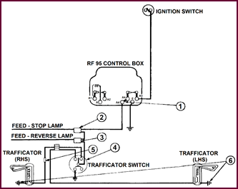 Two cables green with white, and green with red,
lead from this switch and connect, each to one trafficator, through an
additional spring connector (Item 5) also located at the bottom of the
steering column.
Two cables green with white, and green with red,
lead from this switch and connect, each to one trafficator, through an
additional spring connector (Item 5) also located at the bottom of the
steering column.
Figure 25. Wiring diagram for the
trafficator circuit.
In the majority of cases, a separate black
earth lead will be run from each trafficator to an earthing point, as shown at
(Item 6).
The Stop And
Reverse Lamp Circuits
We can now examine the stop lamp and
reverse lamp circuits together.
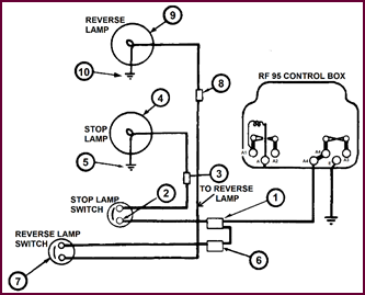 You remember the common green feed wire from A4 on the
control box branched away, still continuing as a green cable from the
first snap connector (Item 1) for the stop lamp. This further green
cable leads direct to the stop lamp switch (Item 2), sometimes a small hydraulic
switch, mounted on the master brake cylinder. From the switch, it proceeds, via
a rubber-covered snap connector (Item 3) direct to the stop lamp (Item
4), and thence to earth (Item 5).
You remember the common green feed wire from A4 on the
control box branched away, still continuing as a green cable from the
first snap connector (Item 1) for the stop lamp. This further green
cable leads direct to the stop lamp switch (Item 2), sometimes a small hydraulic
switch, mounted on the master brake cylinder. From the switch, it proceeds, via
a rubber-covered snap connector (Item 3) direct to the stop lamp (Item
4), and thence to earth (Item 5).
Figure 26. Wiring diagram for stop and
reverse lamp circuits. Note use of snap connectors.
In the case of the reversing lamp, the feed
comes off the second snap connector (Item 6) and proceeds still as a green
cable to the reverse lamp switch (Item 7) usually mounted on the side,
or end of the gearbox, and actu-ated when the reverse gear is selected.
From the switch, the switch wire proceeds
as green with blue via another snap connector (Item 8)
direct to the reverse lamp (Item 9) and thence to earth (Item 10)
through the bulb.
The Screenwiper
Circuit
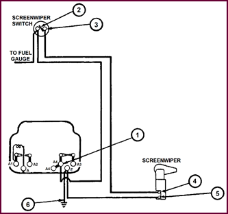 A second green feed wire from the A4 on control box (Item
1) is used to supply the screen wiper and the petrol tank unit. This wire
runs direct to one side of the screenwiper motor switch (Item 2) which
also acts as a junction point for the feed wire to the fuel tank unit. From the
other side of the switch, the wire becomes green with yellow to
one side of the screenwiper motor (Item 4). From the other terminal on
the motor (Item 5) the cable is a black return to the ‘E’
terminal on the control box direct to a good earth on the chassis (Item 6).
A second green feed wire from the A4 on control box (Item
1) is used to supply the screen wiper and the petrol tank unit. This wire
runs direct to one side of the screenwiper motor switch (Item 2) which
also acts as a junction point for the feed wire to the fuel tank unit. From the
other side of the switch, the wire becomes green with yellow to
one side of the screenwiper motor (Item 4). From the other terminal on
the motor (Item 5) the cable is a black return to the ‘E’
terminal on the control box direct to a good earth on the chassis (Item 6).
Figure 27. Diagram of circuit for
screenwiper motor.
The Fuel Gauge
And Petrol Tank Unit
As previously stated, the green feed
wire for this com-ponent is junctioned off the screenwiper switch (Item 1).
From there it connects – still as a green
cable – to the fuel gauge unit (Item 2). From the gauge, the colour changes
to green with black connecting through one or more snap
connectors (Item 3) to the petrol tank rheostat (Item 4). The
circuit is completed through this unit to earth.
In the event of any erratic reading on the
gauge, the first thing to do would be to check the terminals for tightness, and
open and remake the joints at the snap connectors, because either a loose or
corroded connection will seriously affect the operation of the tank unit
rheostat.
Circuit illustration is on Page 15.
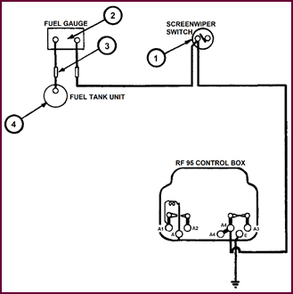
Figure 28.
Wiring diagram for fuel gauge and tank unit.
The Auxiliary Circuits:
A And A2 On
Control Box
 This picture shows a fairly typical layout for auxiliaries which are not under the master control of the ignition
switch, and which may vary somewhat on different vehicles.
This picture shows a fairly typical layout for auxiliaries which are not under the master control of the ignition
switch, and which may vary somewhat on different vehicles.
Figure 29. Components connected to A and
A2 at the control box, and their wiring.
Top centre of the picture shows the
inspection lamp sockets and a cigar lighter. It is usual to place these in the
battery feed circuit before the ammeter. It would serve no useful purpose for
the heavy current discharge from the cigar lighter to register on the ammeter;
it would merely tend to alarm the driver. Similarly if the inspection lamp is
dropped, and shorts as a result of bulb breakage, this would probably damage
the ammeter. On the other hand a radio set for instance, which will have its
own fuse, may be left on accidentally, or it may be in circuit for prolonged periods.
It is therefore desirable that the discharge should be shown on the ammeter.
Similarly, with heavy-current horns such as the Windtones, to con-nect them
through the ammeter would merely register as a violent and alarming oscillation
of the needle when the horn button is closed, so a separate fuse is usually sup-plied
with them, and the supply taken direct off the battery line.
Now examine this picture in detail. Such
components as interior lights, door lights, etc., which may be susceptible to
wiring troubles, will be placed on the ‘A2’ fuse cable colour purple.
Small-current horns such as the Altette horn may also be connected to this
fuse. The radio set with its own fuse, however, can most conveniently be
connected from the ‘A’ terminal of the control box. The supply for the cigar lighter
and inspection plug sockets may be taken from the battery side of the starter
switch as a matter of convenience. The supply for heavy duty horns may be taken
from this point also, or, if no ammeter is installed, the Windtone horn supply
may be taken from the ‘A’ terminal at the control box. At least one car maker
who does not install an ammeter takes the Windtone horn supply from the ‘A2’
fuse, thus eliminating the additional horn fuse. Since there are no other com-ponents
on this fuse, there is no possibility of putting the interior lights out of
action because of a fault on the horn wiring. We have covered this item in some
detail as a number of exceptions to the standard recommended layout may be
found on different vehicles.
The RB.106
Control Unit And Fuse Base
 Where the RB.106 control unit is installed, a separate fuse base is
used.
Where the RB.106 control unit is installed, a separate fuse base is
used.
Figure 30.
Layout of the RB.106 control unit and fuse base.
There are two separate current supplies to
this base:
1. From the ‘A’ terminal on the control box a brown (44/012)
cable connects to the terminal ‘A1’ on the base. The incidental accessories are
connected at ‘A2’, that is, through the fuse.
2. The supply to the ‘A3’ terminal is taken from the ignition
switch ‘A3’ by means of a white (28/012) cable. The ignition accessories, fused and unfused will be connected at ‘A4’
and ‘A3’ respectively.
PART 3. REWIRING
IN SERVICE
General
Vehicle re-wiring work properly organized
is capable of producing a useful revenue, as well as providing an essential
service facility which no motor engineer can really afford to neglect.
The work as a whole falls into four
different categories:
1. Incidental wiring work such
as may be involved in the fitting up of accessory lamps and other components.
2. Renewing single cables within the wiring harness or external to
it.
3. The re-wiring of complete
sections, following damage by collision, fire, etc.
4. Complete rewires involved in
major vehicle over-hauls.
In this latter category it is feasible to
fit a completely new wiring harness, but owing to the multiplicity of models it
is not practicable to make them available as spares; the delay involved in
obtaining a special harness would be completely prohibitive.
In any of the categories mentioned, in
order to carry out a good quality job on an economical and profitable basis,
properly organised stocks of cables, sleeving, jointers, clips, etc. must be
available and the range and quantities of these components will vary according
to the amount of work anticipated.
If rewiring work is to be made a
speciality, a wide range of stock controlled components will be required, other-wise
the work will quickly become uneconomical as the result of delays and time lost
in making-up special bits and pieces.
Within our experience, service complaints
following re-wiring work can be all too frequent, and in this section of the
course we shall attempt to offer some useful guid-ance to those undertaking it.
In every case, the fundamentals of a good
quality, economical job may be assured if:
1. The correct size and quality of cable is used.
2. Adequate stocks of the basic
colours are maintained.
3. Suitable stocks of protective sleeving are available.
4. A full range of quick jointers, junction boxes and other
incidentals are at hand.
Where the work is to be extensive,
additional facilities in the way of guillotines, wire strippers, and other special
tools for fitting up will go far in making the work more profitable.
Finally, although such work may have to be
carried out by relatively inexperienced personnel, a good quick job can only be
expected from an experienced electrician. At the same time, practice will soon result
in increased speed and proficiency.
Cable Stocks
Sizes And Colours
The following cables constitute the minimum
range that is necessary. Quantities can be adjusted to suit the conditions and
volume of work, availability, etc.
The essentials extracted from our Catalogue
No. 502F are as follows:
Starter Cables:
1. 37/20 – for the 12-volt system.
2. 61/20 – for the 6-volt system. .
3. 61/18 – for heavy C.V. work.
4 Earthing braids.
Circuit Wiring Cables:
5. 44/012 max. 22 amperes brown.
6. 28/012 max. 14 amperes yellow, blue, white, purple and black.
7. 14/0l2 max. 7 amperes red,
green, white and yellow.
When all the coloured cables are not
obtainable, short lengths of coloured sleeving will aid identification.
Ignition Cables:
8. 7 mm H.T. Neoprene UM.827.
For motor cycle wiring and miscellaneous purposes:
5 mm Low Tension, rubber covered.
Multi-Core Cables:
An assortment of these is essential for
steering column re-wiring and they are available with from two to seven cores
according to requirements.
Protective
Sleeving And Rubber Grommets
It is essential that all new wiring should
be protected against chafing and exposure at vulnerable points.
For this purpose the most generally
suitable material will be lengths of oil-proof plastic sleeving (PVC) which can
be cut down to suit individual requirements.
The taping together of runs of cable is
unsatisfactory in service, and is instantly recognisable as bad workman-ship. The
following minimum range of six sizes will be required:
Sleeving:
5 mm dia. to carry
one cable.
7 mm dia. to
carry two cables.
11 mm dia. to
carry three to four cables.
15 mm dia. to
carry five to six cables.
18 mm dia. to
carry seven to nine cables.
22 mm dia. to
carry ten cables and over.
Rubber Grommets:
¼” bore to fit ½”
hole.
½” bore to fit ¾”
hole.
1” bore to fit
1¼” hole
Jointers, Snap Connectors And Junction Boxes
The comprehensive range of connectors and
junction boxes illustrated in our Cable Catalogue No. 502F will cover all
requirements.
The only alternative to these connectors is
twisted and soldered joints, a slow business.
In no circumstances should dry joints be
permitted.
These deteriorate badly in service and are
visible evi-dence of bad workmanship.
Cable Clips
A good range of cable eyelets or terminals,
and also spring and screw fixing clips are other essentials to economical
rewiring work, and a comprehensive range is illustrated in our Catalogue No.
502F.
Typical samples are as follows:
1. Junction Boxes: These are available with 2, 4, 6 and 8 terminal
positions.
2. Cable Clips: The essentials here are single and double cable
clips.
3. Cable Harness Clips and Spring Clips for chassis fixing.
4. Cable Eyelets, or Terminals. 3/16”,
¼”, 5/16” and ⅜” eyelets will cover all requirements.
5. Starter Cable Terminals.
6. Battery Lugs and Earth Straps.
This is the simplest form of wiring work.
Wiring Up
Accessory Lamps Or Renewing Single Cables
1. Always use the recommended size of cable and the correct basic
colour, which makes for easy identi-fication subsequently, and also enhances
the appearance of the job.
2. Take great care to ‘feed’ the component from the correct fuse or
terminal point, as we have already detailed.
3. Protect the new wire with sleeving where necessary.
4. Clip up sufficiently close to prevent sagging in service which
would give a consequent untidy appearance.
5. Avoid close proximity to any ‘Hot Spots’ and any moving parts
such as brake cables, etc.
It happens that sometimes a single cable in
the harness may require renewal, and the obvious way to do this is to run a new
cable of the correct size, and major colour, outside the loom. This may be clipped
on to the loom at intervals. Finally cut off the old cable ends where they
enter the harness.
Partial Rewires
A typical service rewiring job will be where
a section of wiring has become damaged due to a smash or a fire.
In this circumstance the best and quite
adequate method is to cut away all the damaged wiring, if possible at a common
point. Then, using either a multi-point terminal block, a junction box or a few
snap connectors, run new cables of the correct size and basic colour to the
various components. In many cases it will be possible to re-use the old cable run,
including the rubber grommets, clips, etc.; otherwise, fit new pieces of
insulating sleeving, rubber grommets and cable clips as required.
Complete
Rewires
In view of the large amount of labour
involved in the re-wiring of any modern vehicle, this job merits careful
consideration and a strictly methodical approach.
Job instructions may only specify a
re-wire, but it is obviously futile to re-wire a vehicle to find afterwards that
when the vehicle is put back into service the generator doesn't charge, or the
battery is flat, and so on.
So, the very first thing to do is to make a
general check-over of all the units, including the lamps and ascertain that
they are in a serviceable condition.
Proceed as follows:
Whilst in contact with the customer make a
visual check of the following:
1. The battery.
2. The distributor, leads, and ignition coil.
3. The generator, belt,
commutator, brushes, bearings.
4. The control box condition.
5. The starter commutator, brushes and bearings.
Listen to the engagement for undue noise.
6. The lighting – check the condition and operation where possible.
Note cracked glasses, ill-fitting rims, etc.
7. The accessories: This general check-over will take about a
quarter of an hour.
Remove any units which may require attention in the way of
overhaul or minor repairs.
The main job of re-wiring the vehicle can then be tackled.
Methods Of
Rewiring
Where only inexperienced labour is
available, the best method is to disconnect the leads from their com-ponents,
and then remove the complete harness intact if possible.
During the removal of the main harness,
some decision will have to be made as to whether such additional cables as
trafficator leads, interior lights, etc., which are in the overhaul, require
renewing. Generally this will not be necessary. On the other hand the leads
passing into the steering column assembly will almost invariably need
replacing. Some care should be taken over this, as such rewiring necessitates
the use of the correct multi-core cable.
Lay the harness carefully on a suitable
size bench and position it with a few stout nails to act as locating pins.
A complete new set of cables can now be
run, using the old loom as a pattern. Tie the cables together at junctions and
apply sleeving where required.
Finally, re-assemble the complete new
harness on to the vehicle and re-connect to the components.
The more experienced man, who fully
understands his circuits, and is thoroughly familiar with the work, will prefer
to chop the old harness out piecemeal and run his new wiring direct in situ.
Whichever method may be employed, a
thorough and final check is necessary when the rewire is completed in order
that a clean and effective job is assured.
This final
check should comprise the following operations:
1. Replace the charged battery on the vehicle, making sure that
earth connections are clean and tight – leave the main battery lead off.
2. Check that oil pipes, speedometer drive, etc., are properly
connected.
3. Check that ALL switches are in the ‘OFF’ position, and that no
odd leads are left disconnected.
4. Connect the main battery lug but do not tighten – this
facilitates emergency removal.
5. Switch on ignition and start engine.
6. Check the charging.
7. Check all lights in turn.
8. Check all accessories in turn.
9. If everything is in order tighten the main battery lug.
Summarising
Whilst it is not possible to cover every
variation in circuit arrangements that a particular vehicle manufacturer may
adopt, the various circuits which have been provided in this book represent the
standard layout employed for most vehicles. If these are properly understood, very
little difficulty will be experienced when confronted with the wiring
arrangement on occasional special models, or even on new model cars now being
produced. Such arrangements will vary only in detail from the general pattern.
In the same way, satisfactory re-wiring
operations can-not be covered in any great detail. Various methods may be
employed which are equally satisfactory, always providing that adequate stocks
of cables and compon-ents are at hand.
