PART 1 – COIL
IGNITION SYSTEMS
Circuit Layout,
Construction And Operation Of The Coil – General
 In considering the ignition system of the
modern (middle 1950s) motor vehicle we are dealing with something vital to
its running. The many refinements introduced on individual components have not
disturbed the simplicity of the ignition system as a whole; in dispensing with complications
reliability has been assured.
In considering the ignition system of the
modern (middle 1950s) motor vehicle we are dealing with something vital to
its running. The many refinements introduced on individual components have not
disturbed the simplicity of the ignition system as a whole; in dispensing with complications
reliability has been assured.
Figure 1. Layout of a Lucas coil
ignition system.
In addition, maintenance has been reduced
to an absolute minimum. The average vehicle user of today is not prepared to
spend a large amount of time under the bonnet, so the aim of design must be – maximum
reliability with minimum maintenance.
This aim has also kept pace with the great
advances which have taken place in engine design and performance, particularly
as regards higher speeds, higher compression ratios, and wide plug gap settings
which coupled with lean mixtures, produce greater fuel economy. You can see
then that the ignition system has a big job to do – if it doesn’t do it well,
even the best engine can become an ‘also ran’.
The Coil
Ignition Circuit
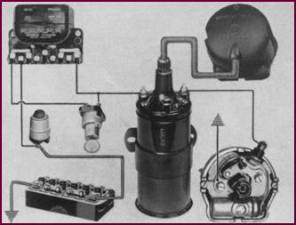
Essentially, the ignition system comprises
the battery, the coil, the distributor, and the spark plugs. The radio suppressors
shown may be optional extras.
For our purposes here, the control box on
the right merely provides a convenient method of supplying the coil and
distributor with current.
The general accessibility of this
particular layout is most commendable, but very frequently the distributor
itself is not so well placed.
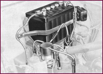
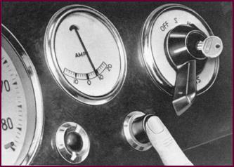
Pictorial
Layout Of Equipment
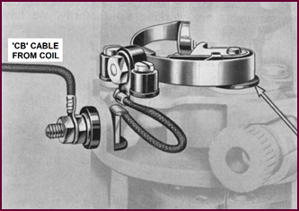
You can see from this picture below how the
components are connected in the circuit.
Let us start at the battery, bottom left.
We pass via a junction point at the starter solenoid, through terminals
A and A1 of the control box, top left, to the ignition switch.
When this key switch is turned to the ‘ON’
position, the ignition coil is fed with current which then passes through the
primary winding in the coil to the C.B. terminal. This terminal is connected to
the distributor. The circuit is completed via the contact breaker points
in the distributor to earth.
The high tension (H.T.) current for the
sparking plugs is taken from the chimney of the ignition coil to the distributor
cap. Then the rotor arm of the distributor conveys the spark to each of the
plugs in the correct firing order.
 We shall now discuss the two main
components of the circuit – the ignition coil and the distributor.
We shall now discuss the two main
components of the circuit – the ignition coil and the distributor.
Figure 2. Pictorial layout of the coil
ignition components.
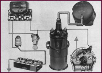
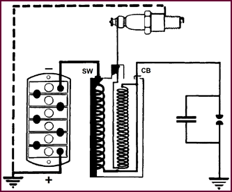
 The Primary
Circuit
The Primary
Circuit
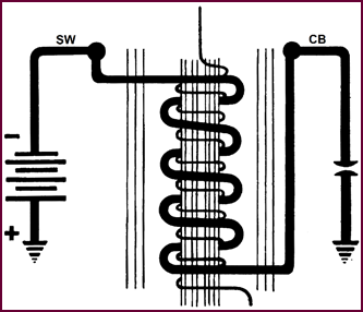
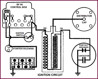
Figure 3. Diagram of primary circuit in
coil
This diagram shows the primary winding of
the ignition coil with the battery connected to the SW terminal and a contact
breaker to the CB terminal. When the contact breaker is closed, current flows through
this primary winding and finds its way back to the positive, or ‘earthed’
terminal of the battery via the engine block and chassis.
The current flowing through the winding
produces a ‘mag-netic field’ around it, as we have illustrated.
To concentrate all the ‘lines of force’,
within the coil, the winding is formed round a laminated iron core and the
whole assembly enclosed by thin iron sheets.
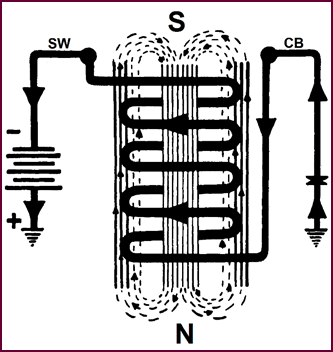
Primary Circuit
With CB Points Open
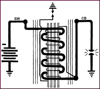
 When the CB points open, the current
stops flowing and the magnetic field collapses. Now if we wind a second coil of
wire on to our core, about 20,000 turns of very fine wire, the collapsing
magnetic field will induce a current impulse in this fine winding. This impulse
can be at a pressure of 20,000 or more volts and represents the available spark
plug voltage.
When the CB points open, the current
stops flowing and the magnetic field collapses. Now if we wind a second coil of
wire on to our core, about 20,000 turns of very fine wire, the collapsing
magnetic field will induce a current impulse in this fine winding. This impulse
can be at a pressure of 20,000 or more volts and represents the available spark
plug voltage.
Figure 4. Primary circuit with
distributor points open.
The Secondary
Circuit
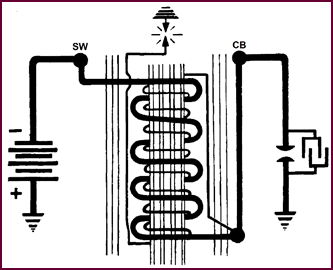
 One end of the fine secondary winding is
connected to the primary – bottom right of the illustration – and the other end
effectively to the spark plug, at the top.
One end of the fine secondary winding is
connected to the primary – bottom right of the illustration – and the other end
effectively to the spark plug, at the top.
Figure 5. The coil secondary circuit.
The return path for this H.T. circuit is
via the engine block, the chassis and the battery earth. The high voltage,
therefore, causes a spark to bridge the plug gaps bet-ween the block and the
insulated electrode. Additionally in this illustration, you can see that we
have shown sparking across the CB points. And this is where a condenser comes
in.
The Coil Circuit With Condenser
 We have already said that when the
primary circuit is opened by the CB points the field collapses and a current is
induced in the secondary winding.
We have already said that when the
primary circuit is opened by the CB points the field collapses and a current is
induced in the secondary winding.
Figure 6. The coil circuit with
condenser.
At the same time the collapsing field also
induces a new voltage in the primary which, although we are only sup-plying the
primary winding at say 12-volts, may rise to 250 or 300-volts. This induced
voltage tries to drive current round the primary circuit just as the points are
opening, causing excessive arcing and sparking at great heat which would
quickly destroy the CB points. So we place a condenser across them, the plates
of which will absorb the excessive voltage and thus reduce its harmfulness.
You will see in the next illustration what
effect the condenser has on the spark plug voltage.
Graph Showing
Effect Of Condenser On HT Output.
This graph shows how the condenser affects
the H.T. output to the plug and also the arcing across the C.B. points.
Left half, without condenser. When the C.B.
points close, the current builds up in the primary winding. When the points
open, the current slowly collapses, arcing occurring across the C.B. points.
Only a small secondary output is obtained
as shown by the dotted line.
Right half, with condenser. When the C.B.
points close, the current builds up as before, but when they open, the current
flow collapses almost at once, putting a very strong ‘kick’ into the secondary
output as shown by the broken line.
Arcing at the C.B. points is almost
eliminated.
 Figure 7.
Graph showing effect of condenser on H.T. output.
Figure 7.
Graph showing effect of condenser on H.T. output.
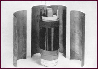
Construction Of
The Ignition Coil
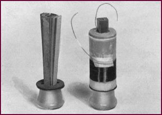 Let us now see how the ignition coil is
constructed. A laminated iron core is fitted into a porcelain base-piece. The
secondary or fine winding, consisting of anything from 6,000 to 20,000 turns of
fine gauge enamelled wire, is then placed over the core.
Let us now see how the ignition coil is
constructed. A laminated iron core is fitted into a porcelain base-piece. The
secondary or fine winding, consisting of anything from 6,000 to 20,000 turns of
fine gauge enamelled wire, is then placed over the core.
Figure 8. Start of construction of an
ignition coil.
A pig-tail take-off is fastened to the end
of the fine secondary wire and brought out at the top as you can see.
 Building The
Coil Primary Winding
Building The
Coil Primary Winding
Figure 9. (Below left) Building the coil
primary winding.
The primary winding, comprising about 300
turns of much heavier wire, is then wound on top of the secondary and brought
out at the top. Winding the primary on top of the secondary helps to dissipate
the heat and makes it easier to insulate the high tension winding from the
case.
A magnetic shield of sheet iron is then
placed round the complete winding.
 Assembling
The Coil
Assembling
The Coil
Figure 10. Assembling the coil.
The whole assembly is then put into a steel
case, the moulded top threaded over the leads, and the moulding with its metal
base-ring soldered on to the case.
At this stage it is desirable to seal the
whole assembly hermetically in order to prevent condensation and corrosion
occurring at any subsequent stage.
For many years this very important sealing
operation was done by extracting all the air and filling the case with bitumen.
More recently a fluid filling technique has become popular. Both methods are
equally effective but with the fluid-filled coils a noticeable result in
service is that the outer case of the fluid-filled coil is rather hot to the
touch, due to the fluid filling which has a better heat conductivity than the earlier
bitumen filled types. This apparent overheating should cause no concern, and is
in fact an indication that the coil is working efficiently.
Auto Transformer
Action
The internal circuit of the coil is of
special interest. You can see that the secondary winding is in series with the
primary. This improves the spark at the plug, the 300 volts induced in the
primary at the contact break being added to the secondary voltage. This effect
is known as auto-transformer action.
Figure 11. Circuit showing auto
transformer action.
The ‘Negative Spark’
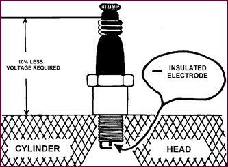 Coils are normally wound to give a
positive earth spark –that is, the spark plug insulated electrode is negative
with respect to the engine block or earth. We usually refer to this as a ‘negative
spark’.
Coils are normally wound to give a
positive earth spark –that is, the spark plug insulated electrode is negative
with respect to the engine block or earth. We usually refer to this as a ‘negative
spark’.
Figure 12. The 'negative spark'.
Several distinct advantages are obtained.
We have the same sparking efficiency at considerably lower voltages –
approximately a 10% reduction in the H.T. voltage re-quired to break down the
gap. By lowering the voltage, the strain on the insulation throughout the
high-tension circuit is considerably reduced – i.e. cable insulation,
distributor cap and all mouldings and plugs.
 We will point out that if the external
connections to the SW and CB terminals of the coil are reversed, current will
flow in the opposite direction through the coil, reversing the H.T. spark polarity. In addition the auto-transformer
action is lost.
We will point out that if the external
connections to the SW and CB terminals of the coil are reversed, current will
flow in the opposite direction through the coil, reversing the H.T. spark polarity. In addition the auto-transformer
action is lost.
Rotor Wear
A further advantage gained with this
negative spark is little or no wear of the rotor arm. The picture on the left
shows how metal is transferred from the rotor to the fixed electrode on each
spark. With the negative spark on the right, the metal transference is in the
opposite direction and wear is divided evenly between the four fixed
electrodes.
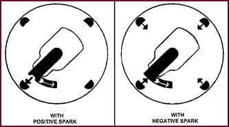 Figure 13. Illustrating rotor wear.
Negative Earth
Coil
Standard Lucas coils are all wound for use
with positive earth battery – but special coils are available for use on
negative earth systems, such coils being connected internally to give a similar
spark polarity to those used with the positive earth system.
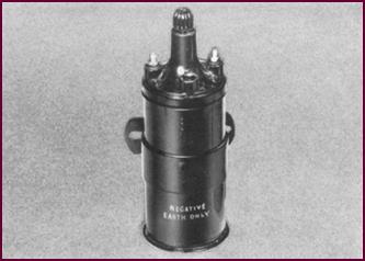 In emergency the negative earth coil can
be used on a positive-earth vehicle.
In emergency the negative earth coil can
be used on a positive-earth vehicle.
Figure 14. The negative earth coil
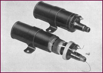
Types Of Coils
We will now discuss some of the reasons why
different types of coils must be produced. Factors other than the ones we have
mentioned – spark polarity and supply voltage – must be taken into consideration.
For instance, the work the coil has to do depends on the engine; coils for
single cylinder engines need nowhere near the same spark performance as those
used on 8-cylinder engines.
The ‘breakdown voltage’ of the plug varies
with different engines, according to the plug gap, the compression ratio, heat,
etc.
Another thing, the speed range of engines
vary; one 6-cylinder engine may run up to 4,000 r.p.m. another, say, up to
6,000 r.p.m.
Our ignition coils, then, must cater for
all these varying requirements. Each coil must be more than sufficient to
fulfil all the operating conditions of a particular engine.
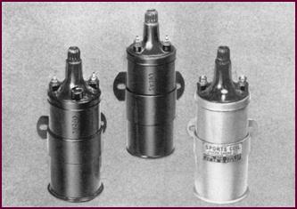 Thus we must produce a wide range of
coils, varying, as far as physical make-up is concerned, in the ratio of
primary to secondary turns, primary current consumption and of course size. And
don’t forget that this primary current has a great influence on the maintenance
necessary to the contact breaker points.
Thus we must produce a wide range of
coils, varying, as far as physical make-up is concerned, in the ratio of
primary to secondary turns, primary current consumption and of course size. And
don’t forget that this primary current has a great influence on the maintenance
necessary to the contact breaker points.
Figure 15. Different types of Lucas
coils.
The fitting of oversize or special coils
can only produce an advantage in performance if accompanied by carburettor and
other adjustments or modifications.
We can sum up by saying that it won’t do to
fit any old coil as a replacement; look up the coil recommended for the
particular engine.

PART 2 – DISTRIBUTORS AND IGNITION TIMING
 The Four
Functions Of The Distributor
The Four
Functions Of The Distributor
Figure 16. The four functions of the
distributor
The four functions of the distributor are:
1. To interrupt the primary circuit of the ignition coil and so
produce the high tension spark. The contact breaker makes this possible.
2. To distribute the high tension spark to the spark plugs, in the
correct firing order. The rotor and distributor cap deal with this.
3. To provide automatic regulation of the spark timing over the
whole engine speed-range. The function of the auto-advance mechanism.
4. To provide means, when required, by the addition of the vacuum
advance mechanism, of varying the spark timing according to the loading of the
engine.
We shall now deal in turn with each of
these functions.
The Cam And
Contact Breaker
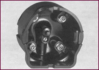
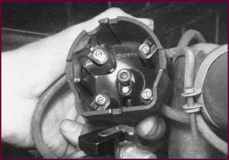
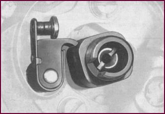 This photograph shows you the normal form
of the cam and contact breaker for a four-cylinder engine.
This photograph shows you the normal form
of the cam and contact breaker for a four-cylinder engine.
The heel of the moving contact rides on the
cam face, causing the contacts to open on each lobe of the cam, thus breaking
the primary circuit of the ignition coil.
Figure 17. The distributor cam and
contact breaker.
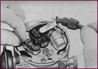
Adjustment of the contact gap is effected
by moving the fixed contact. The gap is set when the contact breaker heel is on
the peak of the cam lobe.
We shall deal more fully with the gap
settings for the various types of cam in a later part of this book.
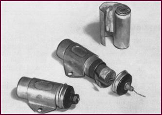 The
Condenser
The
Condenser
Figure 18. The condenser and its
components.
In this illustration we show the condenser,
which is placed in parallel across the C.B. points.
The early types you see here consisted of
two large areas of aluminium foil in strip form, separated by waxed paper.
One strip of foil is soldered to the case
of the condenser, the other to a wire which is soldered to the screw terminal.
Generally speaking, if moisture, dust and
foreign matter can be completely excluded at the time of manufacture, the
effective life of the condenser is practically unlimited.
On the other hand if either the fixing
screw or terminal nut becomes loose in service, a lot of ignition trouble will
be caused due to a weak H.T. spark and burnt C.B. points.
The ignition condenser has a capacity of 0·18 to 0·24 M.fd. which is of considerable importance in obtaining maximum performance from the ignition coil over its full
sparking range.
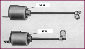
Metallised-Paper
Capacitors
The condensers used in the latest Lucas
distributors are of further improved construction.
The normal foils have been replaced by an
extremely thin coating of aluminium on one side of a paper tissue. A pair of
these coated tissues are then wound together to form the condenser, or
capacitor as we now prefer to call it.
 The effect of a breakdown of the ‘Dielectric’
for any reason is momentarily to produce a short circuit through which passes
the high discharge current from the already charged capacitor; a high
temperature results in the immediate vicinity of the breakdown which vaporises
and oxidises the aluminium and so the fault is cleared, the capacitor
continuing to function normally.
The effect of a breakdown of the ‘Dielectric’
for any reason is momentarily to produce a short circuit through which passes
the high discharge current from the already charged capacitor; a high
temperature results in the immediate vicinity of the breakdown which vaporises
and oxidises the aluminium and so the fault is cleared, the capacitor
continuing to function normally.
Figure 19. Lucas condensers of improved
type.
The energy required to clear a fault is
extremely low and the wax and paper are not damaged in the vicinity of the
breakdown. Since the aluminium oxide is non-con-ducting, no appreciable
decrease in insulation resistance is experienced, even after several hundreds of
internal breakdowns have occurred under test conditions.
Note – The Dielectric is the separating
medium – in this case, paper.
Another factor of great importance is the
size of these new type condensers; they are approximately one third the volume
of the equivalent paper-foil condensers. The capacity is the same as the early types.
The sealing of the condenser has also been
improved, rubber replacing the earlier Bakelite end-cap. You’ll notice too
that the terminal nut arrangement has been replaced by a lead. This improvement
avoids the strain on the end-cap which was formerly experienced when the nut
was tightened.
Distributor
Rotors
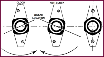
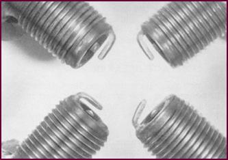
The most noticeable feature of our rotors
is the extended electrode. Most of you know that the reason for this is to
prevent back running of the engine (not backfiring).
The important point is always to have the
correct lead of rotor in the distributor. The direction of rotation of our
distributors is always given viewed from the driving end.
Therefore the extension of the electrode
must always point in the direction of rotation.
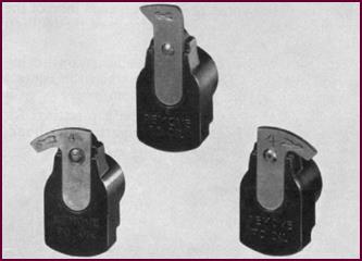 The rotors on the left and centre will
both be fitted to clock distributors; that on the right to anti-clock distributors.
The rotors on the left and centre will
both be fitted to clock distributors; that on the right to anti-clock distributors.
Figure 20. The different rotor arms.
Distributor
Caps
 A major consideration in the design of
distributor caps is the avoidance of ‘tracking’ of the high tension spark under
extreme conditions of humidity. At the same time, ade-quate ventilation must be
provided to allow the corrosive nitrous-oxide produced by the sparking to
escape from the cap.
A major consideration in the design of
distributor caps is the avoidance of ‘tracking’ of the high tension spark under
extreme conditions of humidity. At the same time, ade-quate ventilation must be
provided to allow the corrosive nitrous-oxide produced by the sparking to
escape from the cap.
Figure 21. The distributor cap.
The cap shown here is a good example of a
design which gives the maximum space between fixed electrodes. This reduces
tracking of the H.T. spark between electrodes, or to earth, to a minimum. In addition,
extremely high quality Bakelite is used. Distributor caps for agricultural and
marine equipment are sprayed with a special anti-tracking substance.
Auto Advance
And Spark Timing
 Having shown you mainly constructional
features of Lucas distributors, let us now delve a little more deeply into the
technicalities of the subject.
Having shown you mainly constructional
features of Lucas distributors, let us now delve a little more deeply into the
technicalities of the subject.
The problem of automatically varying the
ignition timing to suit the running of the engine is dealt with in two ways; firstly
by using centrifugal force, and secondly by using the vacuum existing in the
engine inlet manifold – which of course varies with the load on the engine.
A moving weight mechanism built into the distributor
and actuated by centrifugal force, in other words governed by the speed of the
engine, is employed to give the main advance to the ignition timing.
An additional variation is provided by a
vacuum advance unit tapped into the engine inlet manifold and controlled
directly by the throttle position, in other words governed by the load on the
engine.
Note: On Jowett Javelin and Jupiter
engines, the vacuum advance take-off is located in the R.H. carburettor and is
a very precisely positioned drilling. This source of vacuum is very closely
related to the position, at low idle, of the throttle butterfly. A worn spindle
can dramatically have an influence on ignition advance characteristics.
Types Of
Advance Assemblies
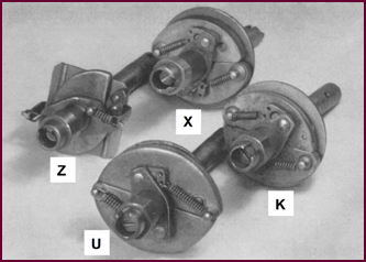 Several types of centrifugal advance
mechanism have been evolved during the last few years, employing different
designs for the moving weights, different spring combinations and different
materials. The ‘X’ type unit shown here has special hardened steel weights and
is designed mainly for motor-cycle work. The ‘Z’ indicates the so-called ‘rolling
weight’ mechanism; the ‘U’ a pressed steel assembly suitable for fitting in the
larger type 6 and 8 cylinder distributors. The ‘K’ mechanism employs die-cast auto-advance
weights.
Several types of centrifugal advance
mechanism have been evolved during the last few years, employing different
designs for the moving weights, different spring combinations and different
materials. The ‘X’ type unit shown here has special hardened steel weights and
is designed mainly for motor-cycle work. The ‘Z’ indicates the so-called ‘rolling
weight’ mechanism; the ‘U’ a pressed steel assembly suitable for fitting in the
larger type 6 and 8 cylinder distributors. The ‘K’ mechanism employs die-cast auto-advance
weights.
Figure 22. Types of advance assemblies.
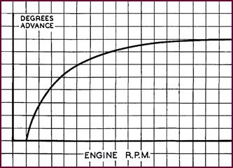
Engine Curve
In building up the many different advance
curves required by the engine manufacturers, we operate from a curve taken from
the engine test which shows the degrees of advance required at different engine
speeds and loads.
In general terms, an engine requires
sufficient spark advance when idling to keep the plugs clean, and there-after
the advance must increase relative to speed, load, mixture, etc.
Figure 23. Graph showing the 'engine
curve'.
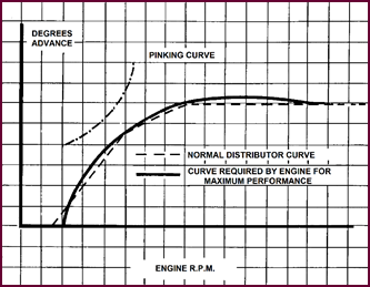
Pinking Curve
All engine tests produce a ‘pinking or detonation
curve’.
At times, to obtain maximum power together
with maximum fuel economy, the ignition advance curve will lie very close to
the ‘pinking’ point and in many overhead valve, high compression engines,
actually crosses the pinking curve at some point or other.
So our job is to produce an advance range
in the distributor which matches the engine manufacturer’s specification.
The dotted line on the diagram shows this
distributor curve.
 Now let’s see the mechanism required to
do the job.
Now let’s see the mechanism required to
do the job.
Figure 24. Graph showing the 'pinking curve'.
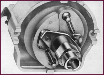
The
Differential Spring Assembly
This is the most popular form of
centrifugal advance. With increasing engine speed, the two weights are flung
out, altering the position of the cam in relation to the contact breaker and
thus advancing the ignition spark.
The rate of advance is controlled by the
tension of the two springs. This type of mechanism employs one light spring to
give a quick initial advance, and a second heavier spring to produce the main
characteristic.
You will notice that there is a looped end
on the heavy spring which allows free action by the light spring at the
beginning of the advance movement.
Figure 25. The differential spring
assembly.
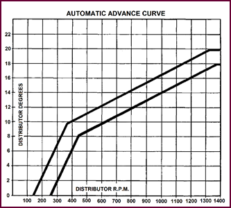
Differential
Curve
This diagram shows the typical spark timing
curve pro-duced by such a differential spring assembly.
The space between the two curves represents
the tolerance allowed.
You will notice the quick initial rate of
advance permitted by the light spring, in this case 8-10° at 400 r.p.m.
The advance then increases more gradually
to a max-imum of 20° at about
1,350 r.p.m. and there is no further increase at higher revs.
 It should be realised that the total
advance range varies considerably for different engines. In fact at the present
time there are over 300 different advance ranges in use, built up expressly to
meet the engine makers’ requirements.
It should be realised that the total
advance range varies considerably for different engines. In fact at the present
time there are over 300 different advance ranges in use, built up expressly to
meet the engine makers’ requirements.
Figure 26. Graph of the differential
curve.
Distorted
Curves
This diagram shows the result of partly
closing the loop in the heavy spring.
The dotted lines represent the advance
obtained when the loop is partly closed; the continuous line, the normal
advance curve.
Now, although it might appear that the
engine has lost its ‘pink’ when revved quickly under no-load conditions, it
will be sluggish when accelerating under load.
 From this, you will realise that the loop
is there for a purpose and must not be bent, squeezed or otherwise ‘adjusted’.
From this, you will realise that the loop
is there for a purpose and must not be bent, squeezed or otherwise ‘adjusted’.
Figure 27. Graph showing distorted
curves.
 Equal Spring
Assembly
Equal Spring
Assembly
Figure 28. An example of an equal spring
assembly.
The other type of auto advance in general
use employs two equal springs and gives a ‘straight line’ advance curve.
The spring loops are always carried by the
inside holes in the toggles.
These toggles have two holes for
interchangeability purposes only.
Straight Line
Advance Curve
The equal spring mechanism produces this
form of ad-vance curve.
You see here that this particular advance
commences at about 400 r.p.m. and progresses steadily to the maximum, which
will again vary considerably with different engines.
 In this case there is no quick initial
advance, permitted by the weaker spring of the assembly we showed you a few
pictures back.
In this case there is no quick initial
advance, permitted by the weaker spring of the assembly we showed you a few
pictures back.
Figure 29.Graph of straight line advance
curve.
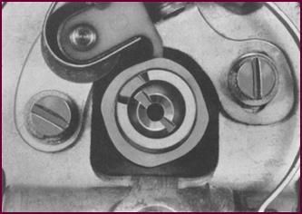
Action Plate
With Holes And Advance Weights With Pins
 A very important point to remember with
both types of advance mechanism is, that manipulation of the springs in no way
affects the total advance given to the spark timing.
A very important point to remember with
both types of advance mechanism is, that manipulation of the springs in no way
affects the total advance given to the spark timing.
 The total advance is controlled by the
size of the two holes in the action plate on the right of the photograph. These
limit the amount of movement of the weights.
The total advance is controlled by the
size of the two holes in the action plate on the right of the photograph. These
limit the amount of movement of the weights.
Figure 30. Advance action plate
assembly.
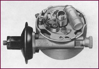
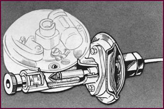
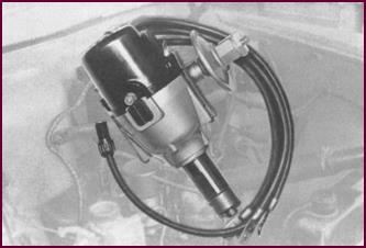
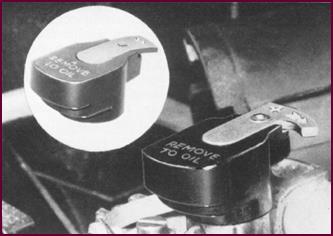
Vacuum Operated
Timing Control
The advance mechanism we have discussed so
far is dependent on r.p.m. alone. Additional control of the spark timing is brought
about by the vacuum unit you see in this photograph. You will remember we said
that, as the unit is connected to the engine inlet manifold, its operation
depends on the depression present in the manifold – that is, its effect varies
with the load on the engine.
Figure 31. Vacuum operated ignition
timing control.
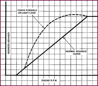
The Suction
Advance Curve
Interpreting this graph, we can say that
the vacuum unit produces additional advance, as shown by the dotted line, when
the engine revs are high, but the load light – that is when there is a high
vacuum in the induction manifold due to the small throttle opening.
When the engine is pulling hard on full
throttle, the vacuum in the manifold is low and the suction advance becomes
wholly or partly inoperative. The spark timing is then solely dependent on the
centrifugal advance.
Figure 32. Graph of the suction advance
curve.
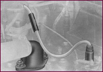
The general effect of the vacuum unit is to
increase the ‘liveliness’ of the engine and, when economy type carb-urettors
and wide spark plug gaps are used, a noticeable improvement in petrol
consumption is possible.
Now how and where is the pipe leading to
the unit attached to the manifold?
Where The
Vacuum Control Is Connected
If the unit is to function correctly, the
point at which it is connected to the manifold is all-important.
 The vacuum pipe should be half sealed
when the throttle butterfly is closed.
The vacuum pipe should be half sealed
when the throttle butterfly is closed.
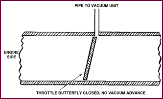 The main condition of operation is that
at idling speed the vacuum unit is out of operation.
The main condition of operation is that
at idling speed the vacuum unit is out of operation.
Figure 33. Relationship of vacuum port
to throttle butter-fly in carburettor body.
Small Throttle
Opening
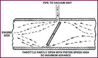 Now with small throttle opening, the
vacuum at the inlet pipe is high and we have maximum permissible advance.
Now with small throttle opening, the
vacuum at the inlet pipe is high and we have maximum permissible advance.
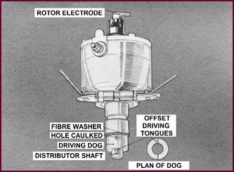 Figure 34. Vacuum drawn with partial
throttle opening.
Figure 34. Vacuum drawn with partial
throttle opening.
Full Throttle
Opening
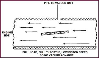 With full throttle opening, we have a low
vacuum and ac-cordingly little or no extra advance from the suction unit.
With full throttle opening, we have a low
vacuum and ac-cordingly little or no extra advance from the suction unit.
Figure 35. Minimal vacuum with throttle
wide open.
Sectioned
Advance Unit
This picture shows the operation of the
unit itself. You can see the plunger which moves the contact breaker plate in
relation to the cam, thus altering the spark timing. A micrometre adjustment is
also included.
Figure 36. A section through the vacuum
advance unit.
These units are not interchangeable by the
way, unless they carry the same identification number, as each unit is made up
to suit a particular engine.
To check the operation of the unit in some
cases, it is only necessary to run the engine at idling speed when, with
changes in the throttle opening, the sliding barrel will be seen to move in and
out.
A cut-away distributor cap should be
employed when the movement is not visible by this method.
Failure to operate is generally the result
of air leaks in the pipe line, usually caused by cracked or chafed pipes or
loose unions. These possibilities should be checked before suspecting a damaged
diaphragm.
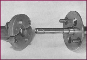
Distributor
Dogs
Having dealt mainly with the distributor as
a separate unit and discussed the method of advancing the spark timing
according to the requirements of the engine, we must now consider how a
distributor should be fitted to a vehicle, from the point of view of timing,
firing order and rotation. This picture shows a correctly fitted driving dog on
the distributor shaft.
Figure 37. Location of distributor drive
dog.
There are two important points to remember.
1. The driving tongues of the dog are in line with the rotor arm.
2. The driving tongues are offset with respect to the centre line
of the shaft and, when viewed from the rotor electrode side, as you are seeing
it now, are to the left of this line.
This guide for fitting is applicable to
both clock and anti-clock distributors.
Drilling The
Distributor Shaft
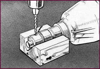 You see here the method of drilling a new
distributor shaft, using the hole in the dog as a guide. To obviate shaft ‘end-float’,
the shaft itself must be pushed down from the rotor end, with the dog hard against
the fibre washer, before commencing to drill.
You see here the method of drilling a new
distributor shaft, using the hole in the dog as a guide. To obviate shaft ‘end-float’,
the shaft itself must be pushed down from the rotor end, with the dog hard against
the fibre washer, before commencing to drill.
Figure 38. Drilling the distributor
drive shaft.
After fitting the pin, caulk over the holes
to secure. The dog must be a tight fit on the shaft.
Driving gears are fitted in a similar
manner, but then the position of the gear in relation to the rotor is
immaterial.
The diameter of the drilled hole is
normally ⅛”; but later supplies
of driving dogs for fitting to D.M. distributors are to be drilled to take a 3/16”
Mill’s grooved pin. In such cases, the diameter of the hole through the shaft
must be 0.187” to 0.188”.
 Installing
And Timing A Distributor
Installing
And Timing A Distributor
Figure 39. Preparation for installing a
distributor.
Firstly, it must always be remembered that
distributors are directional, i.e. either CLOCK or ANTI-CLOCK. The correct
direction of rotation is shown with the identification symbols on the body of
the distributor and is always as viewed from the DRIVING END.
Additionally the letter ‘A’ or ‘C’ appears
on the end of the distributor shaft to denote the rotation of the shaft and
action plate assembly.
Let us take a specimen case – we have a
replacement distributor to fit to an engine and we want to reset the ignition
timing, as this has been accidentally disturbed. We are assuming of course that
nothing is wrong with the engine valve timing.
Ignition Timing
 The engine should normally be timed
according to the engine maker's recommendations, but timing marks are not
always easily accessible or clearly visible, So we shall show you here a simple
method of setting the piston in relation to the ignition spark from the
distributor.
The engine should normally be timed
according to the engine maker's recommendations, but timing marks are not
always easily accessible or clearly visible, So we shall show you here a simple
method of setting the piston in relation to the ignition spark from the
distributor.
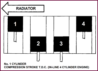
Figure 40. Inline four-cylinder engine
ignition timing.
First take out the sparking plug from No. 1
cylinder – this is usually the front cylinder of the block, that is, the one
nearest the radiator. (Note: For Standard motor cars, the cylinder closest to
the scuttle, or firewall, is number 1 with the remaining cylinders numbered
forwards.) Then turn the engine over slowly with the starting handle, with your
thumb tight over the spark plug hole, until compression is felt. Bring the
piston slowly to the top of its stroke, using where possible, a piece of wire
as a final guide to the piston travel. Leave the piston set at T.D.C. on the
compression stroke.
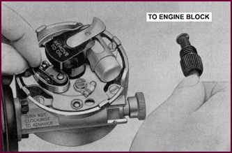
Setting The
Rotor Position
Having set any micrometre advance adjuster
on the distributor approximately at the half-way position, next place the
distributor in position with the rotor pointing to what we can call for our
purpose the No. 1 electrode in the distributor cap – that is pointing to about
7 o’clock. This is only a preliminary rough setting, being of necessity
governed either by the tongues of the distributor dog-drive or by the pitch of
the gears. A finer adjustment should then be made by turning the body of the
distributor until the contacts are just opening, still with the rotor pointing
to the No. 1 electrode. Clamp the distributor pro-visionally at this setting.
It is not important which electrode in the cap we make No. 1. We must start
from somewhere, however, and it’s just a matter of convenience. What is
important is that the plug lead from the cylinder we’ve positioned for firing,
that is No. 1, is sparked from the correct electrode position in the
distributor cap, that is the one in line with the rotor. For simplicity's sake,
then, we’ll connect No. 1 electrode in 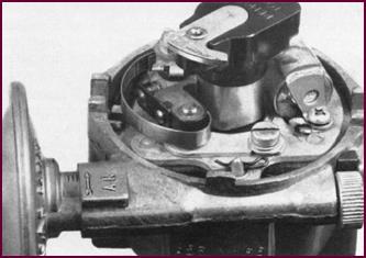 the cap to No. 1 cylinder.
Figure 41. Setting the rotor position
for No, 1 cylinder.
Cam And Rotor
Assembly
 If any difficulty is experienced in obtaining
this initial setting of the timing, correctly and easily, the cam should be
examined.
If any difficulty is experienced in obtaining
this initial setting of the timing, correctly and easily, the cam should be
examined.
Figure 42. Setting the cam and rotor
assembly.
On four cylinder distributors the cams are
handed left and right, and as shown in the illustration, the most apparent
difference is the position of the rotor locating slot in relation to the cam lobes.
Unless the rotor is correctly positioned in
relation to the cam the running of the engine may be seriously affected.
This does not apply to the 6 cylinder cam
where the rotor locating-slot is centrally placed in relation to the cam lobe as
shown in the right-hand illustration.
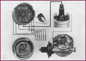
Rotation And
Firing Order
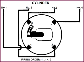
Before we can connect the remaining plug
leads, we must know two things – the direction of rotation of the distributor
rotor and the engine’s firing order.
The rotation can quickly be established
from the rotor itself – the extended brass electrode is usually arrowed – or
the distributor body is marked. But, just to make absolutely certain, turn the
starting handle just a fraction and watch the rotor. We will assume for the
moment that the firing order is known, and that for the particular 4-cylinder
engine it is 1, 3, 4, 2. The rotation we’ll take to be as is indicated on the
rotor illustrated. The plug leads can then be inserted into the distributor
cap, the lead from No. 1 cylinder going to No. 1 electrode, from No. 3 cylinder
to the next electrode (in the direction of rotation), No. 4 following and
finally No. 2.
 Connect up the vacuum advance unit if
fitted and the engine should run.
Connect up the vacuum advance unit if
fitted and the engine should run.
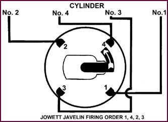 Figure 43. Rotation and firing order.
Figure 44.
Rotation and firing order, Jowett Javelin/Jupiter.
Timing: Final
Adjustment
The final adjustment of the timing is
something which can only properly be dealt with during a practical demonstration.
It can be set in the garage fairly accurately by vacuum gauge, but, this method
on its, own is not accurate enough as a final adjustment. This final setting
can best be carried out on the road. To obtain the best results it must be done
scientifically. One engine manufacturer arrives at the best engine performance by
timing the vehicle with a stop-watch over a series of test runs, conditions
being identical for each run – that is, the pre-vailing wind must be the same,
the run must be made in the same direction and the vehicle accelerated to the same
m.p.h. figure.
The distributor can be moved slightly if
necessary by slackening the clamp and moving the distributor body, thus varying
the point at which the contacts open. The micrometre adjustment will allow an extremely
fine setting to be made.
Firing Order
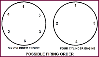
Where the firing order is not known, and
cannot be found from the engine maker’s instruction manual, two possible
sequences exist for a four cylinder engine:
1, 3, 4, 2 or
1, 2, 4, 3.
 Thus, after finding T.D.C. on the
compression stroke of No. 1 cylinder, check which is the next cylinder to fire
by taking out all the plugs and testing for compression on either cylinders 2
or 3. The one coming up to compression will establish which of the two possible
orders it is. Staying with the four cylinder engine’s firing order, in the case
of the Jowett Javelin and Jupiter, the actual firing order is 1, 4, 2, 3. This
information can be found on the brass chassis number plate located on the body,
behind the radiator (firewall).
Thus, after finding T.D.C. on the
compression stroke of No. 1 cylinder, check which is the next cylinder to fire
by taking out all the plugs and testing for compression on either cylinders 2
or 3. The one coming up to compression will establish which of the two possible
orders it is. Staying with the four cylinder engine’s firing order, in the case
of the Jowett Javelin and Jupiter, the actual firing order is 1, 4, 2, 3. This
information can be found on the brass chassis number plate located on the body,
behind the radiator (firewall).
Figure 45. 6-Cylinder and 4-Cylinder
firing orders.
The same method can be applied to a 6-cylinder
en-gine, once again there are only two possible firing orders, as indicated:
1, 5, 3, 6, 2, 4
or,
1, 4, 2, 6, 3, 5.
Figure 46. Jowett Javelin and Jupiter
firing order.
In every case, the method of connecting the
plug leads to the distributor cap is the same; start from No. 1 cylinder to No.
1 cap electrode and continue round the cap in the cylinder firing order, NOT
forgetting to follow the rotation of the distributor rotor.
PART 3 – DISTRIBUTOR
TYPES AND APPLICATIONS
Before showing you photographs of the various
Lucas distributors, we must consider for a moment the symbols used for
identifying the different types.
Type Symbols
Prefix Description for Symbol
B Ball
Bearing
D Distributor
D1 1st
Design
D2 2nd
Design
D3 3rd
Design
F Flange
mounting
H Horizontal
cable outlets
K Small
cast iron body, with moulded contact breaker base and die-cast auto-advance
weights
KY Die-cast
body with pressed steel contact breaker base
L Double
contact breakers
M Micro
control
P Porous
Bushing
U Large
cast iron body with moulded contact breaker base
V Built-in
vacuum control
X Hardened
steel auto-advance mechanism
Z Rolling weight auto-advance mechanism
Numerals
1. Suitable
for single cylinder engines
2. Suitable
for twin cylinder engines
4. Suitable
for four cylinder engines
6. Suitable
for six cylinder engines
8. Suitable for eight cylinder engines
Prefix or Suffix
*A Fitted
with automatic advance and retard
* This symbol is omitted from latest models as they are
all fitted with automatic advance mechanism.
 The DK Type
Distributor
The DK Type
Distributor
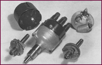
 And now the units themselves. This
picture shows the early standard DK distributor.
And now the units themselves. This
picture shows the early standard DK distributor.
Figure 47. The DK Type of Lucas
distributor.
 It has a cast-iron body, a Bakelite
contact-breaker base and the shaft turns in porous bronze bearing bushes.
It has a cast-iron body, a Bakelite
contact-breaker base and the shaft turns in porous bronze bearing bushes.
Nowadays this type is used mainly for ‘insulated
return’ circuits on light commercial Vehicles and motor cycles. When used for
this latter purpose it becomes type ‘DKX’ (hardened steel weights).
The DKY And DKZ
Distributor
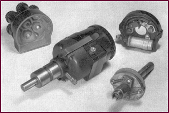
 These distributors are again standard
types, but they are fitted with a die-cast body and metal contact breaker base.
These distributors are again standard
types, but they are fitted with a die-cast body and metal contact breaker base.
Figure 48. Lucas DKY and DKZ type
distributors.
Die-cast or rolling weight auto-advance
mechanism is used. The bearings for the shaft are still porous bronze bushes.
These types are usually applied to light
cars and light commercial vehicles with medium-speed four cylinder engines.
The DZ And DX
Distributor
These types are made with a larger die-cast
body. Pressed steel is used for the contact breaker base and either the
hardened steel or the rolling weight auto-advance mechanism is fitted. Porous
bronze bearings are again employed.
These are particularly applicable to high
compression four and six cylinder engines.
Figure 49. Lucas DZ and DX type
distributors.
The DVZ And DVX
Distributors
The main features of these distributors is
the built-in vacuum advance unit. An oil well is also incorporated for
lubrication.
Figure 50. Lucas DVZ and DVX type
distributors.
The top bearing for the distributor shaft
is a ball race, a porous bronze bush being still retained for the bottom
bearing.
The DVZ and DVX distributors are applied to
four and six cylinder engines which require vacuum advance.
 The DULF And
DU Distributors
The DULF And
DU Distributors
Figure 51. Lucas DULF and DU type
distributors
These models are standard productions with
a large dia-meter body, usually of cast iron, except for the flange-mounted
version, (bottom left in the picture) which may be die-cast.
A Bakelite contact breaker base is fitted,
which may carry single or twin contact breakers. The twin contact breaker model
is generally applied to eight cylinder engines such as the Ford V8 and the Rolls
Royce B80. Large six cylinder engines usually take the DU or DULF with a single
contact breaker.
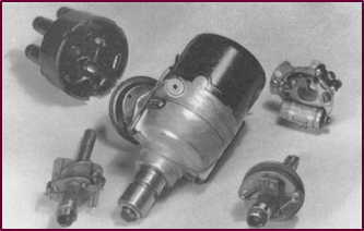
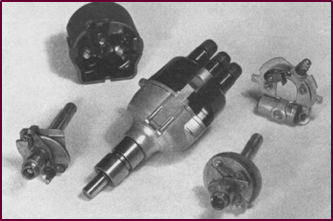
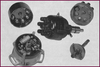
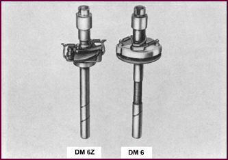
The DM Distributor
More recently a new range of distributors
has been intro-duced and is now widely used on most British cars.
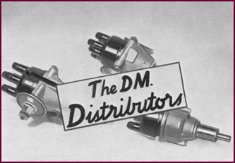 There are two main models, the DM4 and
DM6, applied to high performance four and six cylinder engines. Variations of
these two models fit a ball bearing.
There are two main models, the DM4 and
DM6, applied to high performance four and six cylinder engines. Variations of
these two models fit a ball bearing.
Figure 52. Lucas DM type distributor,
A smaller model DM2A4 may be used for
medium compression four cylinder engines together with a similar model known as
the D2A4 which does not incorporate a vacuum advance unit.
Design Features
Here you see the main features of these DM distributors.
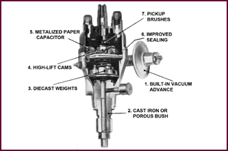 The vacuum unit is built into the
distributor and incorporates a micrometre adjustment.
The vacuum unit is built into the
distributor and incorporates a micrometre adjustment.
Figure 53. Features of the Lucas DM
series distributor.
The bearings may be either cast iron or
porous bronze bushes. A ball bearing is fitted, as we have mentioned, in some
models.
Die-cast or
rolling weight auto-advance mechanism is used.
The cam is a new design called the ‘High
Lift’ – we shall tell you more about this in a moment.
We have already discussed the new metalized
paper capacitors – you will remember their ‘re-healing’ property if a
dielectric breakdown occurs, and their comparatively small size.
The sealing of the distributor cap has been
improved, rendering the unit much more dustproof – the necessary ventilation is
still of course provided. And finally the H.T. pick-up brushes are designed to
act as radio suppression resistors. But now let us examine some of these
features in detail.
The Vacuum
Advance Unit
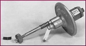 This unit, as we have said, is built
into the distributor and incorporates a fine adjustment for the spark timing.
This unit, as we have said, is built
into the distributor and incorporates a fine adjustment for the spark timing.
Figure 54. The DM type's micrometer
adjustable vacuum advance unit. This enables accurate timing adjustment.
Whilst generally similar to the earlier
models, each vacuum unit is made up for a particular engine and you will
remember that we stressed that units are inter-changeable only if the
numbers on the locking tabs are identical.
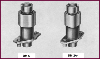
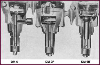 Bearings
Figure 55. Lucas DM series shaft
bearings.
Three types of shaft bearings are used. The
DM6 is fitted with a long cast-iron bush.
This bush is part of the shank and is not
renewable. The lower part of the bearing is lubricated by oil mist from the
engine and the upper part by means of a grease lubricator.
The second type of bearing consists of a
single long bronze bush, shown here in the DM2P.
The bronze bushes are easily replaceable,
and, as they are used in conjunction with hardened steel shafts, are expected
to give extremely long service. The lubrication is again by oil mist from the
engine.
 A third type of bearing consist of a
porous bronze bush at the bottom with a grease packed ball bearing at the top,
and no additional lubrication is required. This bearing assembly is signified
by the letter ‘B’.
A third type of bearing consist of a
porous bronze bush at the bottom with a grease packed ball bearing at the top,
and no additional lubrication is required. This bearing assembly is signified
by the letter ‘B’.
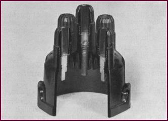
The Auto
Advance Mechanism
Two types of auto-advance assembly are
fitted in the D.M. distributors.
 The ‘rolling weight’ mechanism is shown
here in the left of the picture. This arrangement may employ either equal or
differential springs.
The ‘rolling weight’ mechanism is shown
here in the left of the picture. This arrangement may employ either equal or
differential springs.
Figure 56. DM Series auto-advance
assembly.
The die-cast weight assembly on the right
closely follows the earlier pattern, but is much heavier in construction; also,
brass toggles are used instead of steel.
The High Lift
Cam
 All D.M. distributors fit the new ‘high
lift’ cam. This form gives a very quick break of the contacts, increased ‘cam
dwell’ – that is a longer closed period – and generally results in increased
life of the contact points.
All D.M. distributors fit the new ‘high
lift’ cam. This form gives a very quick break of the contacts, increased ‘cam
dwell’ – that is a longer closed period – and generally results in increased
life of the contact points.
 We shall further discuss the contact
setting with the ‘high lift’ cam in the maintenance part of this lecture, but
it certainly won’t hurt to say now that the contact gap should be set and
maintained at 0.014” – 0.016” in service.
We shall further discuss the contact
setting with the ‘high lift’ cam in the maintenance part of this lecture, but
it certainly won’t hurt to say now that the contact gap should be set and
maintained at 0.014” – 0.016” in service.
Figure 57. DM Series high-lift cam.
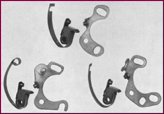
The Contact Set
The contact breaker assembly used in the
D.M. range of distributors has the same characteristics, a ½” rocker arm and
long stainless steel spring, as those fitted to the earlier distributors.
Figure 58. Contact sets for Lucas DM
Series.
The spring anchorage may be slotted in the
end of the spring, or alternatively, looped as shown in the left hand picture;
this being the latest design which has now been standardised for all the DM
range.
It is very simple to identify the various
sets from the illustrated spares lists we supply.
The Distributor
Cap
This picture shows a typical cap design.
Both the sealing and the ventilation have been improved. The H.T. pick-up brush
contains a high percentage of resistive material and is designed to act as a
radio and television sup-pressor. With this type of cap, no further suppressor
is required in the distributor-coil H.T. cable and none should be fitted.
Figure 59. Lucas DM Series distributor
cap.
Caps are manufactured with both vertical
and horizontal H.T. lead outlets.
PART 4 – TESTING
The testing and servicing of coil ignition
equipment can be considered from two separate stand-points.
Firstly, there is the testing and servicing
of the distributor and ignition coil, this is the province of the specialist
who will have a proper testing machine available together with the relevant
data appertaining to the whole range of this equipment.
The more general requirement is for the motor
engineer to be able to diagnose the cause of intermittent misfiring or complete
breakdown of the ignition system in situ on the vehicle. Such preliminary
diagnosis will generally precede unit testing or major overhaul. At the same
time the most common faults which develop arise as the result of general neglect
and can be put right at once.
These ‘service’ faults frequently involve
the ignition circuit as a whole, that is the wiring, switches, etc., quite
apart from the distributor and ignition coil units themselves. By the use of a
simple routine test procedure any such faults can easily and quickly be located
and corrected. If, at this stage satisfactory performance is not regained, it
may become necessary to bench test the coil and distributor unit as a pair.
For our own purpose when setting out this
routine, which can easily be memorised let us assume that we are faced with a
complete failure of the ignition system on the vehicle.
In this circumstance we must first prove
the current supply, i.e. the battery and then follow the current path to the
ignition coil and distributor. For this purpose it is possible to completely
check the low tension or primary circuit of the supply and the ignition
units in four operations, with a further three operations to
check the high tension system and the condenser.
The Distributor
And Coils
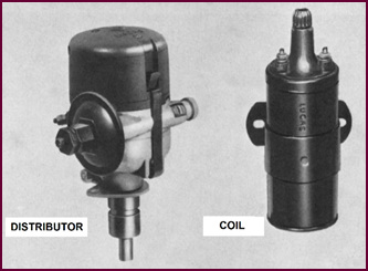 Ignoring for the moment the battery, the
two main components in the ignition system are the distributor and coil. Each
takes its share of the blame for nearly all ignition faults.
Ignoring for the moment the battery, the
two main components in the ignition system are the distributor and coil. Each
takes its share of the blame for nearly all ignition faults.
Figure 60. The two foremost components
of the ignition system.
Pictorial
Diagram Of Ignition Circuit
 However, let us see exactly how these
units fit into the complete ignition circuit. Here we see a pictorial diagram
of the system used on the post-war car.
However, let us see exactly how these
units fit into the complete ignition circuit. Here we see a pictorial diagram
of the system used on the post-war car.
Figure 61. Pictorial layout of the coil
ignition system.
The primary circuit: we must have a
satisfactory current supply from the battery to the primary winding of the
ignition coil. This current must be interrupted at the right moment by the
contact-breaker points, in order to induce current in the secondary circuit and
so produce the ignition spark.
The secondary circuit consists of
the high-tension winding in the coil, the distributor rotor and cover, the high
tension leads and spark plugs.
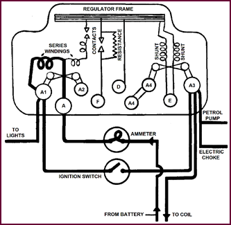
 Wiring
Diagram Of Ignition Circuit
Wiring
Diagram Of Ignition Circuit
Figure 62. Wiring diagram of ignition
circuit.
A more precise idea can be obtained from
this wiring diagram (maybe, a copy should be carried in the car’s glovebox).
Following the ignition circuit through from the battery, the feed wire is
tapped off from the starter solenoid to terminal ‘A’ on the control box. From
there it passes through the load winding of the regulator to terminal ‘A1’. The
circuit then continues to the ignition switch.
 When the ignition is switched on, ‘A3’ of
the control box is ‘live’. You can follow the circuit from the other side of
the ignition switch to the ‘A3’ terminal. The ‘SW’ terminal of the coil is then
fed from this ‘A3’ terminal. The circuit continues through the primary winding of
the coil to the ‘CB’ terminal, the contact breaker being connected to this
terminal. The circuit is completed via the contacts to the distributor earth,
and so back to the battery via the chassis.
When the ignition is switched on, ‘A3’ of
the control box is ‘live’. You can follow the circuit from the other side of
the ignition switch to the ‘A3’ terminal. The ‘SW’ terminal of the coil is then
fed from this ‘A3’ terminal. The circuit continues through the primary winding of
the coil to the ‘CB’ terminal, the contact breaker being connected to this
terminal. The circuit is completed via the contacts to the distributor earth,
and so back to the battery via the chassis.
The high tension side of the system starts
from the secondary winding of the coil at the chimney, through to the rotor,
and then via the distributor cap to the plugs. The circuit is again
completed via the chassis, in this case the block, earth strap and so
back to the battery.
In the following tests, we shall prove the
circuit at most of the points we have mentioned, i.e. the battery, ‘A’ and ‘A1’
terminals, at the, ‘A3’ terminal, at the coil ‘SW’ and ‘CB’ terminals, finally
checking the H.T. side of the circuit from the coil chimney, through the rotor,
the cap and on to the spark plugs.
Lamps Switched
On
 Having given you an overall picture of
the ignition system, what should be the first step when we are confronted with
a complete failure? Surely the first point is to see whether there is any
current available to the system at all.
Having given you an overall picture of
the ignition system, what should be the first step when we are confronted with
a complete failure? Surely the first point is to see whether there is any
current available to the system at all.
Figure 63. Test with all lamps switched
on.
The quickest method is to switch on the
headlights and operate the starter motor.
If the starter operates satisfactorily,
without dimming the lights excessively, we can safely assume that the battery
is not the cause of the breakdown.
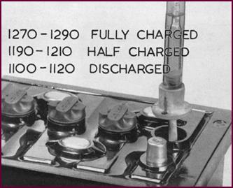
Hydrometer Test
The test we have just shown you is of
course a quick check for the battery.
This Hydrometer check will give a more
exact idea of the state of charge of the battery. The readings should be at
least between 1.200 – 1.210, that is, about half-charged.
If in a very low state of charge, the
voltage of the battery may be so greatly reduced when the starter is operated
that the ignition coil will not spark.
Figure 64. Taking the hydrometer readings.
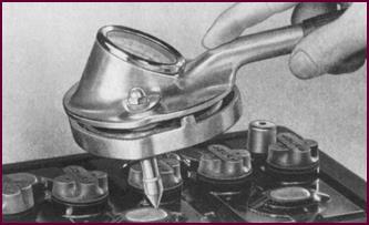
Heavy Discharge
Test
This test, which puts a heavy discharge
across the battery, will complete an exact check on the condition of the cells.
Figure 65. The heavy discharge test.
The voltmeter should register approximately
1.5-volts per cell. The cell reading should remain constant throughout a
15-seconds application of the tester.
'A1' And 'A' At
Control Box
If we prove that the battery is serviceable
and that the car lights are working satisfactorily, we have actually proved
that the current supply arrives at the ‘A1’ terminal of the control box.
With the ignition ‘on’, we find out next,
with the voltmeter, whether the ‘A3’ terminal of the control box is ‘live’, as
this terminal feeds the coil and the an electric petrol pump. In some cases
this ‘A3’ terminal is located on a fuse block mounted separately from the control
box.
Let us assume that there is no fault so
far. The next thing to do is to check straight through the primary or L.T.
circuit of the ignition system. From terminal ‘A3’, which we’ve just checked,
the current should arrive at the ignition coil.
Figure 66. Control box wiring diagram,
ignition circuit.
Volts At ‘SW’
Terminal Of The Coil.
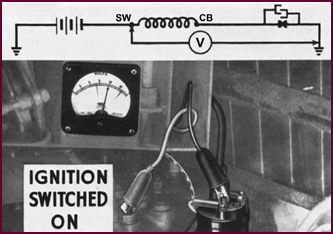 Connect the voltmeter between the ‘SW’
terminal on the coil and an earthing point.
Connect the voltmeter between the ‘SW’
terminal on the coil and an earthing point.
Figure 67. Voltage reading at 'SW'
terminal on coil.
Full battery volts should be registered on
the voltmeter, irrespective of whether the C.B. points are open or not,
although it is preferable for them to be closed and the coil taking current. If
no voltage is shown we have an open circuit in the cable between the control box
‘A3’ terminal and the coil ‘SW’ terminal. This fault can soon be remedied.
But let us assume that we do get full
battery volts at the ‘SW’ terminal of the ignition coil. It pays to pull at the
cable near the coil, thus making sure that the terminal nuts are not loose and
that there is no intermittent break in the cable inside the covering. You can
see what connections we’ve made at the top of Figure 67.
 Volts At ‘CB’
Terminal
Volts At ‘CB’
Terminal
We must next see whether the circuit is
intact through the coil. Open the contact breaker points and, with a volt-meter
connected to the ‘CB’ terminal of the coil, we should still get full battery
volts. If no voltage is shown at this point, there are two possibilities.
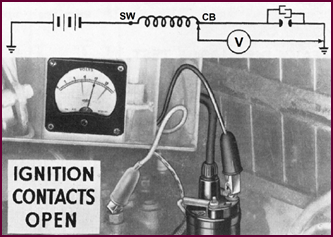 The first is an open-circuited primary in
the ignition coil. The second possibility is an earth inside the distributor.
Both points can easily be checked by disconnecting the wire from the ‘CB’
terminal and taking another voltage reading at the coil terminal itself.
The first is an open-circuited primary in
the ignition coil. The second possibility is an earth inside the distributor.
Both points can easily be checked by disconnecting the wire from the ‘CB’
terminal and taking another voltage reading at the coil terminal itself.
Figure 68. Checking voltage at 'CB'
terminal on coil.
A zero reading will then indicate a break
in the primary winding, a full voltage reading, a short to earth on the
distributor.
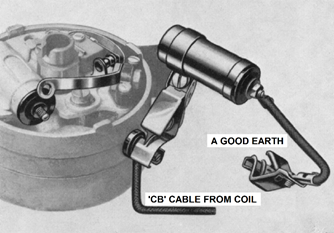
Possible
Earthing Points
Such an earth can be at any of the
following points:
a) The CB cable between the ignition coil and the distributor L.T.
terminal – left of the picture.
b) The flexible lead between the L.T. terminal on the distributor
and the moving contact.
c) On the moving contact itself – the insulating washer may have
been omitted for instance. This washer is arrowed in the picture.
d) Or finally at the condenser – this however is unlikely.
 If none of these show up, that is, if we
get full battery volts, the next step is to CLOSE the contact breaker
points.
If none of these show up, that is, if we
get full battery volts, the next step is to CLOSE the contact breaker
points.
Figure 69. Possible earthing points in
the distributor.
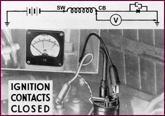
Volts At The ‘CB’ Terminal With
Contacts Closed
With the contact breaker points closed, we
should now have a zero reading on our voltmeter.
You see, by closing the points we are
shorting out the meter, providing that the distributor internal circuit is not
faulty.
 If any voltage reading still shows, it, is
probable that the points are dirty, oily or oxidised slightly, and may be
cleaned up.
If any voltage reading still shows, it, is
probable that the points are dirty, oily or oxidised slightly, and may be
cleaned up.
Figure 70. Voltage test at the 'CB'
terminal at coil.
If heavily burned and showing grey green
deposit, suspect the condenser.
Sometimes there is a bad earth between the distributor
shank and the engine block and chassis. If the battery voltage does fall to
zero with the contacts closed, we need only check that the cam is opening the contact
breaker points properly when rotating, and we have completed the check on our
primary circuit.
Checking The
Secondary Or H.T. Circuit
 We now proceed to check the secondary or
H.T. spark circuit with which we can conveniently include the con-denser. The
H.T. test is carried out in three operations.
We now proceed to check the secondary or
H.T. spark circuit with which we can conveniently include the con-denser. The
H.T. test is carried out in three operations.
Figure 71.Testing the H.T. (secondary)
circuit.
The most convenient way of checking the
H.T. circuit of the ignition coil is to use a short length of H.T. cable, one
end of which can be pushed into the chimney of the coil and used as a ‘jumper lead’.
The other end of the lead must be held ¼” away from the engine block.
Our ignition switch is still ‘ON’ remember.
Flick the contacts from the closed position
and, if the coil and condenser are good, we shall have a good spark thrown to
the block at each flick of the contacts.
If NO spark is thrown, then we must have a defective
H.T. winding. Remembering that we have already cleaned the points, sparking may
occur even if the condenser is open circuited. The engine may run – but very
roughly.
Jumper
Condenser.
We can easily check the position by fitting
a ‘jumper’ or substitute condenser. After disconnecting the original condenser,
the ‘jumper’ can be conveniently connected between the L.T. terminal on the
distributor and earth.
 If we still have no spark when we flick
the contacts, we know definitely that the secondary winding of the coil is
faulty. If on the other hand the spark is now improved and the engine runs much
more smoothly, then the original condenser was inoperative. This might be due
to the condenser screws being loose and this point should be checked first.
Otherwise, the original condenser was faulty.
If we still have no spark when we flick
the contacts, we know definitely that the secondary winding of the coil is
faulty. If on the other hand the spark is now improved and the engine runs much
more smoothly, then the original condenser was inoperative. This might be due
to the condenser screws being loose and this point should be checked first.
Otherwise, the original condenser was faulty.
Figure 72. Testing with a 'jumper'
condenser.
Assuming that this last test shows the H.T.
winding and the condenser to be in order, it remains only to test the
distributor rotor and the distributor cap and H.T. cables.
 Checking The
Rotor
Checking The
Rotor
Figure 73. Testing the rotor arm.
Examine the rotor first. If this is
punctured it will earth the spark on to the cam head. A tiny puncture is often
invisible to the eye and we therefore test in the following manner.
Hold the piece of H.T. cable, still
connected to the coil, on to the rotor electrode as shown. If on flicking the
contact breaker points a spark is thrown to the rotor, then the latter is
defective.
Under very damp conditions, any faint
sparking which may be visible, will be due to static leakage and must not be
confused with the true H.T. spark.
Final Check
Our final check concerns the distributor
cap and the H.T. cables.
Burnt or cracked caps can easily cause
misfiring but are rarely the cause of complete breakdown.
Mechanical fractures are usually easy to
find by visual examination. Tracking between
segments is likewise visible.
 Burning around the pick-up electrodes due
to a sticking pick-up brush is more elusive and may only cause misfiring.
Burning around the pick-up electrodes due
to a sticking pick-up brush is more elusive and may only cause misfiring.
Figure 74. Making the final test on the
H.T. circuit.
The H.T. cables are much more likely to
cause such a breakdown and all leads should be checked to see that the
insulation is in good condition. In our case, with an assumed complete failure,
the lead in question would be the main H.T. cable from the coil to the distributor.
Any chafing at this point would of course earth the H.T. spark completely. Pay
particular attention to these H.T. leads when they pass through any sort of
clips or channelling, or when a suppressor is in circuit.
With this check, the testing procedure for
the whole of the ignition system has been completed. There are only seven
operations in all: four for the primary circuit and three for the secondary;
and the only tools we need are a voltmeter, a test condenser and a piece of
H.T. cable.
PART 5 – SERVICING
Maintenance
Points
The maintenance necessary to obtain
consistently satisfactory performance from coil ignition equipment is very
small and for standard routine servicing or ‘checking-over’ purposes there are
NINE items which require periodic inspection. Three of these require fairly
regular attention. They are: the contact breaker points and gap, the general
lubrication of the bearings and auto-advance mechanism and thirdly the spark
plugs.
We have listed these points in the system
which require periodic attention.
1. H.T. Leads
2. Distributor
Mouldings
3. Rotor
4. Contact breaker set
5. Bearing bushes
6. Auto-advance
7. Suction advance
8. Coil connections
The Spark Plugs
 You have probably noticed that we did not
list spark plugs. The importance of good, clean plugs with properly adjusted
gaps cannot of course be over-estimated. Set the gaps to the manufacturer’s
recommended setting, making sure that they are all even.
You have probably noticed that we did not
list spark plugs. The importance of good, clean plugs with properly adjusted
gaps cannot of course be over-estimated. Set the gaps to the manufacturer’s
recommended setting, making sure that they are all even.
Figure 75. Setting the sparking plugs.
The H.T. Leads
H.T. leads in a poor condition are often
the cause of inter-mittent misfiring, even of complete break downs. General
deterioration and cracking of the cable covering occurs with time, particularly
if the leads are allowed to chafe against metal.
See that the leads are kept clean and free
from oil and, as we have said, run as far as possible away from the metal parts
of the engine, thus minimising wear due to vibration.
Figure 76. Keep H.T. leads away from
metal components.
The Distributor
Mouldings
 With the increased use of high voltage
ignition coils, distributor mouldings have been developed with a very open
construction to prevent ‘tracking’. The mouldings should be kept clean and dry
inside and out, and the carbon brush checked for free movement in its holder.
With the increased use of high voltage
ignition coils, distributor mouldings have been developed with a very open
construction to prevent ‘tracking’. The mouldings should be kept clean and dry
inside and out, and the carbon brush checked for free movement in its holder.
Figure 77. Inspect the distributor cap inside
and outside at regular intervals.
 The Rotor
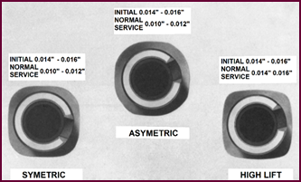 Figure 78. The rotor arm should be inspected
and cleaned at regular intervals.
Figure 78. The rotor arm should be inspected
and cleaned at regular intervals.
Rotors call for little or no maintenance in
service. Just see that they are kept clean and dry. And remember too that
rotors can’t be replaced indiscriminately – make sure that the rotor is the
correct one for the job, i.e. that the extended electrode points in the
direction of rotation. And, by the way, there is a difference between a
four and a six-cylinder rotor. The design of the six cylinder rotor is visible
in the inset.

The Contact
Breaker
The next point for attention is the contact
breaker set. The C.B. points must of course be maintained in good con-dition,
either by cleaning and facing up, or by the fitting of a new set if the old
points are badly burnt.
Figure 79. Maintenance of the contact
breaker set.
Closing-in of the C.B. points gap due to
wear on the ‘heel’ can be practically eliminated by a little light grease applied
to the cam face or the felt pad when provided.
The points’ setting should be maintained at
a minimum of 0·010” to 0·012” (0·254 to 0·301 mm) to obtain full per-formance with
all Lucas ignition coils irrespective of working conditions.
A gap setting of 0·014” to 0·016” (0·36 to
0·41 mm) when fitting new contacts will ensure that after the initial ‘bedding-down’
the final gap will not close below 0·010” (0·254 mm). There is an exception to
these settings when a distributor is fitted with the new ‘high lift’ cam.
Here the contact gap should be set and maintained at 0·014” to 0·016”
(0·36 to 0·41 mm).
The Three Types
Of Cam
Here you can see the difference between the
cam forms. The older type symmetric and asymmetric cams, as we have said, are
used with a contact gap of 0·010” to 0·012” (0·254 to 0·301 mm), the ‘high lift’
with the gap increased to 0·014” to 0·016” (0·36 to 0·41 mm). You can recognise
the ‘high lift’ cam by the much sharper form of the lobes.
Figure 80. The three types of cam
profiles.
You are probably wondering why there are
different cam forms. Stated simply, cam development has had to keep pace with
engine development. The early symmetrical cam was adequate for the ignition performance
required by engines up to 1949, and gave equal open and closed periods of the
contacts.
The asymmetric cam by reason of its special
form helped to reduce contact breaker noise and at the same time provided a
slightly increased dwell period. The contact breaker setting with this cam was
somewhat critical and it was subsequently superseded by the current production ‘high
lift’ cam.
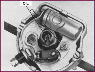 This cam with a sharp profile provides a
very fast break, a long dwell period and is suitable for any type, high, or
medium to low speed engines.
This cam with a sharp profile provides a
very fast break, a long dwell period and is suitable for any type, high, or
medium to low speed engines.
We hope that the summary will impress upon
you that the contact gap must be set according to the cam form.
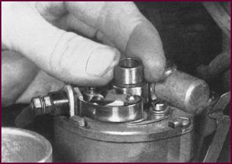 Distributor
Bearings
Distributor
Bearings
Figure 81. Checking the distributor
bearings.
Excessive side play at the cam head,
generally caused by wear of the distributor bearings will cause uneven running
and missing at speed.
Check for possible wear by putting side
pressure on the cam and watching the movement at the contact breaker points.
The variation in the gap should not exceed 0.004”.
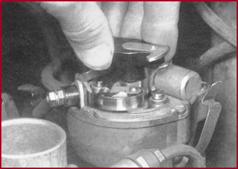 The Auto
Advance Mechanism
The Auto
Advance Mechanism
Figure 82. Checking the auto-advance
mechanism.
Sluggish operation or sticking of the
centrifugal auto-advance mechanism will cause failure of the engine to
accelerate and general erratic performance. Check the auto-advance for freedom
of movement by turning the rotor heel against the spring tension.
There should be no ‘back-lash’ at the start
and the cam and rotor should return fully to the original position when
released.
The
Auto-Advance – Lubrication
The Auto-advance should be lubricated with
light machine oil at the points shown, particularly if any sticking is
observed.
Figure 83. Lubricating the auto-advance
mechanism.
The Suction
Advance
Sticking or failure of the suction advance
will cause poor engine acceleration, and sluggish running. An increase in the
petrol consumption may also be noticed. The mech-anism can be checked manually,
and then observed with the engine running at varying speeds. If the suction
dia-phragm is working correctly, the plunger should move freely in its guide. In
some instances a cut-away dis-tributor cap will have to be used for the
movement to be seen. The picture shows how the cap should be cut away.
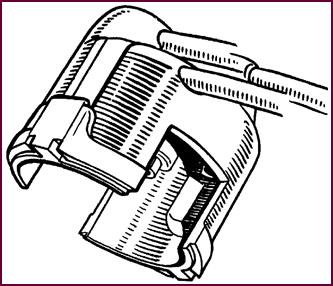 Note: In the late 1950s there was a
swing to transparent distributor caps so that the action could easily be seen.
Note: In the late 1950s there was a
swing to transparent distributor caps so that the action could easily be seen.
Figure 84. A distributor cap with observation
cut-outs.
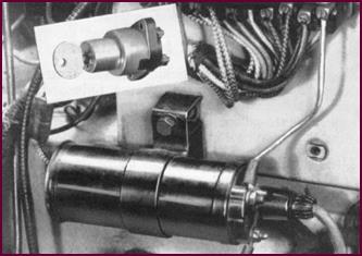 The Ignition
Coil And Switch Connections
The Ignition
Coil And Switch Connections
Loose low-tension (L.T.) connections cause
misfiring and even intermittent or total failure.
High-tension (H.T.) leakage at the coil
chimney due to the accumulation of dirt and moisture on the moulding will frequently
cause misfiring when accelerating under load.
A quick check of the L.T. circuit wiring,
paying particular attention to connections at the switch and coil, plus an
inspection of the coil chimney, will complete the maintenance of the ignition
circuit.
Figure 85. Maintain a check of all coil
ignition cables and their connections. Always ensure a sound connection at
engine block to chassis (earth).