PART ONE:
WORKING
PRINCIPLES
The Starting
Motor
It must first be understood that energy
cannot be created from nothing; it can however be converted from one form to
another.
In the case of the starter motor, we employ
electrical energy – the electrical current from a battery – and convert it
into mechanical energy, the type of energy required to turn over the engine of
a motor vehicle.
To understand how this conversion is
brought about – how we can use the battery current and produce turning movement
– we must consider how two magnetic fields can interact and produce such a movement.
We can then go back a stage further and see how these magnetic fields are
produced from the battery current.
The Production
Of Turning Movement
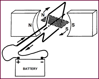
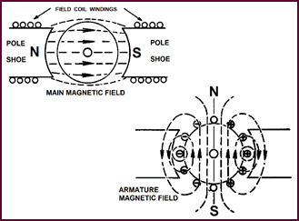
These illustrations, Figure 1, show
two magnetic fields. The main one is produced by the horseshoe magnet and the
second, which we shall call the 'armature magnetic field', exists around the
bar magnet.
In the combined picture at the bottom, this
bar magnet is pivoted at the centre.
 Every time
the two magnets are brought into close proximity to
each other, their fields interact, become distorted and, in trying to revert to
normal, force the pivoted magnet into movement.
Every time
the two magnets are brought into close proximity to
each other, their fields interact, become distorted and, in trying to revert to
normal, force the pivoted magnet into movement.
Figure 1. The production of turning
movement.
But the movement will be restricted: the
bar magnet will turn only as long as like magnetic poles are next to one
another. You can see that the two North Poles repel each other, so do the two
Souths producing the turning move-ment. (You will remember this fundamental
rule of magnetism.) But, when the magnet has rotated through half a revolution,
unlike poles will be together and no further movement will occur. One way to
continue the rotation would be suddenly to reverse the polarity of the bar
magnet i.e. change over the North and South poles.
The Magnetic
Effect Of An Electric Current
 In the build-up of our starter motors, we
do not use per-manent magnets to produce the two magnetic fields: we make use
of the electric current from the vehicle battery.
In the build-up of our starter motors, we
do not use per-manent magnets to produce the two magnetic fields: we make use
of the electric current from the vehicle battery.
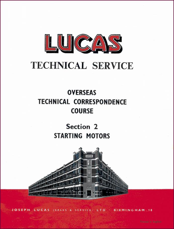
Figure 2. Illustrating the magnetic
effect of an electric current taken from a battery.
Here we show current passing through a
conductor in the direction indicated by the arrow. A magnetic field will be
produced around the conductor. The lines of force of the magnetic field are
formed in a definite pattern, dependent upon the direction of the current flow.
In this case, the pattern is anti-clockwise in form, as we have indicated by
the circular arrows.
A cross-section of the wire is also shown, illustrating
the circular pattern of the magnetic field.
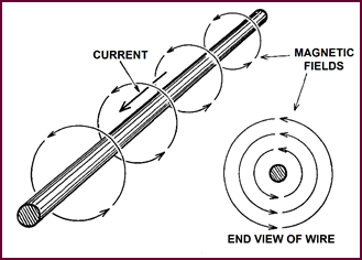
Concentrating
The Magnetic Field
 Using a coil of wire instead of a single
conductor greatly increases the magnetic effect. The soft iron core adds to
this by concentrating the lines of magnetic force into the coil area. The
result is a powerful magnet.
Using a coil of wire instead of a single
conductor greatly increases the magnetic effect. The soft iron core adds to
this by concentrating the lines of magnetic force into the coil area. The
result is a powerful magnet.
Figure 3. Concentrating the magnetic
field.
The polarity of the magnetic field varies
with the direction of the current flow. In this particular case the current
flowing from battery positive through thee coil to the negative produces a
North pole on the left and a South  on the right. If the battery were
connected the other way round, thus reversing the current flow through the
coil, the polarity of the field would also be reversed.
on the right. If the battery were
connected the other way round, thus reversing the current flow through the
coil, the polarity of the field would also be reversed.
Having established that a magnetic field
can be produced round a coil of wire, let us consider how we employ two such
fields in the starter motor.
We will deal first with the main magnetic
field – if you remember, this was provided by the horseshoe magnet in our
original simple illustration, Figure 1.
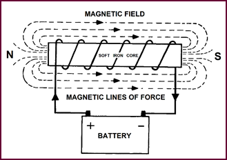
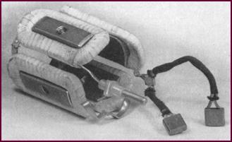
Production Of
The Main Magnetic Field
The main field is created by using soft
iron which be-comes easily magnetised by current flowing through the
surrounding coils of wire. These coils are known as field coils and the blocks
of soft iron, specially shaped to con-centrate the magnetic strength into the gap,
are called pole-pieces or pole-shoes.
 All we have done in effect is to cut the
soft iron of the previous illustration into two halves and shape the end of
each half. In addition, the coil winding has been divided into two. The
windings are so arranged that the pole-pieces are of opposite polarity.
All we have done in effect is to cut the
soft iron of the previous illustration into two halves and shape the end of
each half. In addition, the coil winding has been divided into two. The
windings are so arranged that the pole-pieces are of opposite polarity.
Figure 4. Production of the main
magnetic field.
In this particular case, a north pole is
formed on the left and a south on the right. The field magnets we have pro-duced
remain fixed at this polarity.
Producing The
Armature Magnetic Field
And now let us consider the second magnetic
field, generally termed the 'armature magnetic field'. You will remember that
this was formed by the pivoted bar magnet in our early illustration, Figure
1.
This loop of wire, passing battery current,
produces an equivalent effect. The current flow in the wire gives rise to a
magnetic field whose plane is at right angles to the loop itself – as we have
indicated by the shaded area, which you can consider as representing our
original bar magnet.
With the current flowing round the loop in
the direction shown by the arrows, a north magnetic pole will be pro-duced on
the left, and a south on the right. If we reversed the current flow, we should
also reverse these poles.
Figure 5. Producing the armature
magnetic field. Above right.
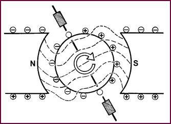
Interaction Of
The Two Magnetic Fields
Here we show the armature loop in the
magnetic field of the main magnet. The two fields interact, the two norths and
the two souths repelling one another, thus forcing the pivoted loop into
movement.
 If the battery current still remains in
the same direction, the loop will cease rotating after half a revolution, that
is when the north and south poles line up.
If the battery current still remains in
the same direction, the loop will cease rotating after half a revolution, that
is when the north and south poles line up.
Figure 6. The interaction of two
magnetic fields.
However, if we could arrange matters so
that as the loop turn so the pole coming round to the fixed north pole of the
field magnet was itself always north; and that app-roaching the fixed south
pole was always south, the repelling action would invariably take place,
continually impulsing the loop as it rotated.
The Principles
Of Commutation
This effect is achieved by joining the ends
of the loop to two metal segments before they pick up the battery current.
Brushes actually form the contact between
the battery and the segments.
Let us consider the top left hand
illustration first, where the black half of the loop is at the top, with its
end connected via the segment to positive battery.
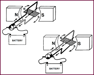 In this position, the current flowing
through the loop produces a north pole opposite the fixed north pole of the
field magnet; and a south opposite the fixed south pole. Repulsion occurs and –
the loop begins to rotate.
In this position, the current flowing
through the loop produces a north pole opposite the fixed north pole of the
field magnet; and a south opposite the fixed south pole. Repulsion occurs and –
the loop begins to rotate.
Figure 7. Explaining the principles of
commutation. Note that the two sketches certainly are different.
Now look at the bottom right-hand sketch,
where you will see that the loop has moved through half a turn, so that the
white section is now on top. But, you will notice that the magnetic field
produced by this section is still north in polarity; in other words it will
still be repelled by the fixed north pole. Likewise, the black section of the
loop which previously produced a north pole, is now producing a south as it
moves opposite the fixed south pole. Repul-sion
will therefore occur again and the rotation will continue.
What has happened is that the direction of
the current in the wire itself has changed because the segments have moved
under brushes connected to opposite sides of the battery. You can see in the left-hand
illustration that the black half of the wire loop is connected to positive at
the battery; whereas in the right hand illustration it is con-nected to
negative at the battery, which means that the current flow in that section has
reversed. The same can be said for the other section.
With a change in the current, comes a
change in polarity. As the loop rotates, therefore, the two sections assume the
polarity of the fixed poles they approach.
We shall be discussing this reversal
effect, known as commutation, a little later on.
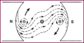
Opposing Fields
Let us examine this interaction of the two
magnetic fields a little more closely, to give you a more graphic idea of how
the turning movement is produced.
Figure 8 shows
the main field produced by the north and south pole pieces. We also show, in cross-section,
the magnetic lines of force surrounding the armature loop.
Imagine the current at 'A' flowing through
the conductor towards you. The magnetic lines of force produced around 'A' in
an anti-clockwise direction will interact with the lines of force of the main
magnetic field between the north and south pole-pieces. The result of this
interaction between the two fields is a distortion of the lines of force. A
strengthening of the field occurs under the conductor at point 'A'.
Figure 8. Opposing fields.
Now magnetic lines of force have elastic
properties, and, if we regard these distorted lines of force as stretched
elastic threads which tend to straighten themselves, we can see that a pressure
will be exerted under the conductor at point 'A' and the loop will be urged
round in a clockwise direction.
Similarly, it can be seen that at point 'B',
where the current through the conductor and hence the magnetic field is in the
opposite direction, that a strengthening of the field will occur above the
conductor and the pressure exerted will assist the movement of the loop in a
clockwise direction.
Thus by the interaction of two opposing
magnetic forces, mechanical energy or more specifically turning move-ment has
been produced from electrical energy.
We shall now consider the more practical
aspects of the starter motor, beginning with the production of the main
magnetic field.
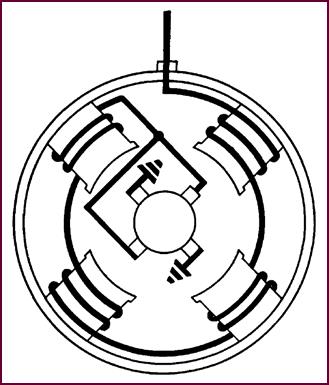
The Main Field
In Practice
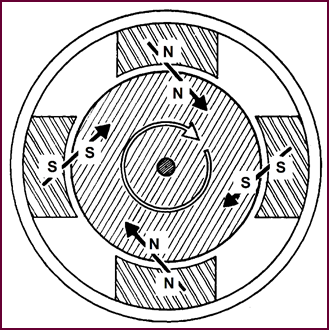
 The theoretical motor we have discussed
so far used a main magnetic field of one North and one South pole. In practice,
the majority of our machines use four pole shoes surrounded by field coils,
thus producing a concentrated field with four magnetic poles.
The theoretical motor we have discussed
so far used a main magnetic field of one North and one South pole. In practice,
the majority of our machines use four pole shoes surrounded by field coils,
thus producing a concentrated field with four magnetic poles.
Figure 9. The main field in practice.
The field coils are wound so as to produce
alternate North and South poles.
 The two brushes and the main terminal
visible in this picture, Figure 9, are the means by which the battery current
enters and leaves these field coils.
The two brushes and the main terminal
visible in this picture, Figure 9, are the means by which the battery current
enters and leaves these field coils.
In this particular arrangement, the four
coils are wound in series, i.e. the current passes in line from one coil to the
next. As this current is normally in the region of 200-300 ampéres, heavy copper strip is used for the
coil windings. For the same reason, two brushes are necessary, each taking half
the total current consumption, to avoid elec-trical losses and overheating. The
brushes themselves contain a high percentage of copper mixed with the carbon.
We shall be referring to these two brushes from now on as the insulated
brushes. You can see that the leads to them are covered by fairly heavy
braiding.
Earth Brushes
 A corresponding pair of non-insulated or
earth brushes is also used in the starter, again with the aim of passing the
heavy currents without excessive losses which result in overheating.
A corresponding pair of non-insulated or
earth brushes is also used in the starter, again with the aim of passing the
heavy currents without excessive losses which result in overheating.
Figure 10. Brushes riveted to a starter
motor's end cover.
When we deal with the starter circuit, you
will see exactly at what point these earth brushes fit into the picture.
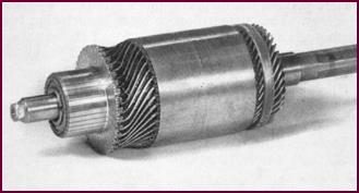
The Armature
The second magnetic field in our starter
motor is prod-uced in practice by this armature which, although far removed in
appearance from our simple wire loop and two segments, is essentially the same.
Instead of one loop, we use many, but each end of every loop is still connected
to a copper segment. All the segments are insulated from one another and rolled
together to form what is called a commutator. This provides the running surface
for the brushes which carry current to and from the armature windings.
The whole assembly is built round a solid
steel shaft. The core, which actually carries the windings, consists of a whole
series of soft iron laminations. (You will remember how iron helps to
concentrate the magnetic field.)
Laminations are used instead of solid
metal, to reduce the heating effect of harmful electric currents known as 'eddy
currents' which are produced when the armature revolves in the main magnetic
field. The laminations offer a sufficiently high resistance to render these
currents harmless as far as heating effect is concerned.
Figure 11. The armature.
Having shown
you the complete assembly, let us examine the
components more closely.
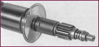
Individual
Armature Components
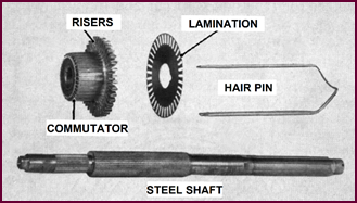 In Figure 12 you see the
individual components. Let us commence with the steel shaft which forms the
centre of the whole assembly. The short splined section on the left carries the
commutator. The next splined section is larger in diameter and longer to carry
the soft iron laminations of the core. The heavy splined section on the right
does not concern us at this stage as it forms part of the drive assembly.
In Figure 12 you see the
individual components. Let us commence with the steel shaft which forms the
centre of the whole assembly. The short splined section on the left carries the
commutator. The next splined section is larger in diameter and longer to carry
the soft iron laminations of the core. The heavy splined section on the right
does not concern us at this stage as it forms part of the drive assembly.
Figure 12. The armature components.
The commutator is built up of individual
copper segments, with an insulating strip between adjacent segments.
The commutator 'risers' provide convenient soldering
points for the ends of the armature loops.
These armature
loops, aptly termed 'hairpins', pass through the slots
in the laminations; the ends are then twisted so as to connect with the correct
commutator segment.
To continue
our study of the starter motor, we must examine the
method of interconnecting the individual loops in the complete armature
winding.
Method Of
Armature Winding
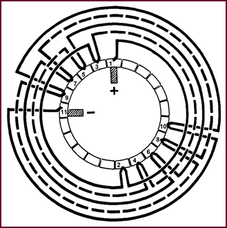
In Figure 13, we have reduced the
number of loops in the winding so as to simplify matters, which also means of course
that we reduce the number of segments in the commutator accordingly. Our aim is
to illustrate the order in which each loop is connected.
If we start at segment 1, we can follow the
lower loop round to the back of the commutator where it ends at segment 2. A
second loop then continues the winding round to segment 3. From 3, we pass to
4; from 4 to 5 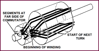 and so on.
Figure 13. Method of armature winding.
You will notice that the ends of each loop
are staggered to opposite sides of the commutator, being in practice always 180°
apart, less one segment.
This method of winding is known as 'wave winding'.
The Armature Magnetic
Poles
Here you see the magnetic poles produced by
these windings. The current flow in them is such that two north poles are
formed at the exterior of the armature and on opposite sides.
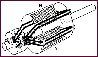 If you imagine the remainder of the
windings in position round the armature, at right angles to the ones shown, the
current flow in them would be arranged to produce two south poles.
If you imagine the remainder of the
windings in position round the armature, at right angles to the ones shown, the
current flow in them would be arranged to produce two south poles.
Figure 14. The armature magnetic poles.
The total effect would be to produce four
alternate north and south poles round the exterior of the armature.
These are the four magnetic poles which
oppose those of the main field of the pole-pieces.
The Opposing
Magnetic Poles
 Here the illustration shows the opposing
polarities of the two magnetic fields. The main field produced by the four pole
pieces is shown surrounding the alternate north and south poles of the armature
field.
Here the illustration shows the opposing
polarities of the two magnetic fields. The main field produced by the four pole
pieces is shown surrounding the alternate north and south poles of the armature
field.
Figure 15. The opposing magnetic poles.
You will remember that the poles must
oppose one an-other for repulsion to occur and the armature to rotate.
The Armature –
Wave Winding
 Although this diagram may appear
complicated at first sight, it merely represents in diagrammatic form what we
have already shown you – that is, the method of inter-connecting the individual loops in the wave-wound armature.
Although this diagram may appear
complicated at first sight, it merely represents in diagrammatic form what we
have already shown you – that is, the method of inter-connecting the individual loops in the wave-wound armature.
Figure 16. The armature, wave winding
explained.
We shall go a stage further and follow the
path for the battery current round the armature from where it enters at one of
the positive or earth brushes to the adjacent insulated or negative brush –
i.e. the point at which the current leaves the armature.
Let us follow the windings, commencing from
the positive brush, in position on the No. 1 segment. The first loop carries
the current to the No. 2 segment at the opposite side of the commutator. You
can see that the two ends of the loop are 180° opposed, less one segment. From
segment 2, the winding loops round to 3 – that is the segment next to the
starting point. The current path con-tinues to segment 4 and from there to 5;
from 5 to 6 and so on to number 11, which is the segment under the negative
brush. This completes one path for the current from one positive brush to one
negative.
But we have simplified matters here for the
sake of clarity; there is actually another current path from the positive brush
on segment 1 round the armature in the other direction to the negative. This
means that the battery current is passing through the whole of the armature
windings, producing a strong magnetic field.
The magnetic
effect will further be multiplied by the current
flowing between the other two positive and negative brushes which we have
omitted. These two are joined in parallel with the ones shown here and will be
passing half the total current consumption of the starting motor.
 In a production model, there are usually
nine commutator segments between brushes of opposite polarity, which of course
further increases the number of armature wind-ings and accordingly the magnetic
effect. Wave-winding the armature in this way, puts all the windings in circuit
when the brushes are passing current.
In a production model, there are usually
nine commutator segments between brushes of opposite polarity, which of course
further increases the number of armature wind-ings and accordingly the magnetic
effect. Wave-winding the armature in this way, puts all the windings in circuit
when the brushes are passing current.
Commutation
 In the last diagram, we followed the
current path round the armature between one positive and one negative brush;
but we considered it in a stationary position. We must now show what happens
when the armature begins to turn.
In the last diagram, we followed the
current path round the armature between one positive and one negative brush;
but we considered it in a stationary position. We must now show what happens
when the armature begins to turn.
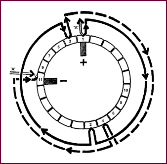
Figure 17. Brushes in contact with
segments 1 and 11.
Look at the top illustration first. It
shows the brushes in position on segments number 1 and number 11 – in other
words the brush – segment relation is that of the previous picture. But we have
dispensed with the windings not immediately concerned with the changes that
take place when the armature begins to rotate. Thus segment 3 is joined
directly to segment 11, instead of being, looped via the intermediate segments,
5, 6, 7, 8, 9 and 10.
In the top illustration then, current
enters the armature via the positive brush on number 1 segment. Here the
current splits into two, one half indicated by the arrowed black line
travelling clockwise via segment 2 to segment three; then still
clockwise from 3 via 4 to 11. The other half of the current would travel
round an equal number of windings to the negative brush on segment 11, but in
the opposite direction. The start and finish of these other windings is shown
by the short arrowed white lines (A).
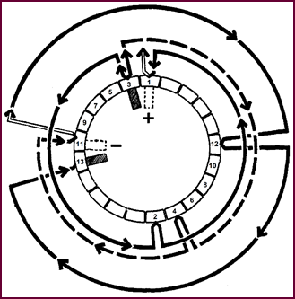
Now consider the lower illustration. The
armature has rotated so that the brushes are now on segments ad-jacent, to the
previous ones – i.e. positive brush on segment 3; negative on segment 13.
Now, you will remember from our earlier
simple illust-ration of commutation that for the armature to continue rotating
the magnetic poles produced by it must always oppose the fixed poles of the
main field magnets. In other words, some change must take place to maintain
this repulsion by like poles.
Figure 18. Current flow into segment 3.
In the lower illustration (Figure 18)
then, current will now flow into the armature at segment 3. It will split as before
into two halves, one half continuing clockwise round the armature via segment 4
to segment 11 – i.e. in the same direction as before in this part of the winding.
The current flow continues clockwise from 11 via 12 to 13 taking in an
additional loop and segment.
But the other half of the current is
anti-clockwise in direction from segment 3, travelling round the loop via
segment 2 back to segment 1 – i.e. it opposes the previous flow in these two
loops – just look at the top illustration again and see how the direction of
the current has changed from clock to anti-clock.
Summing up then: while the current flow in
these two loops has reversed, the overall effect is to maintain the same
direction of current in all the other windings. Mag-netically, this means that
the original polarity of the four armature poles has not altered despite the
fact that the armature itself has rotated one set of segments. If then,
armature north poles were originally produced opposite the main north poles,
the same condition would remain in the new position and repulsion would again
occur to continue the rotation.
In practice, therefore, we can consider
that the com-mutator, in reversing the current flow in two loops, ensures that
the original magnetic pattern of the armature field remains constant, north
poles invariably being repelled by north poles; south poles invariably being
repelled by south poles.
The exact moment at which the reversal of
the current occurs in the two loops is all important to the correct running of
the starter motor in service.
 It is arranged to take place when two
adjacent segments are making contact with
the same brush. As the brushes are wide enough to cover two segments, this
condition is al-ways present no matter what the position of the armature.
It is arranged to take place when two
adjacent segments are making contact with
the same brush. As the brushes are wide enough to cover two segments, this
condition is al-ways present no matter what the position of the armature.
Figure 19. Positive brush in contact
with segments 1 & 3.
In Figure 19, we show the positive brush
making contact with segments 3 and 1. This effectively shorts out the two loops
between these segments at the moment when the current reversal is taking place.
The commutation may be regarded as perfect if the reversal is completed before
segment 1 is clear of the brush. On the other hand if this segment leaves the
brush before the complete reversal of the current, sparking will occur between
the brush and segment, which will be extremely injurious to both.
Brush
Positioning
A further word now about the positioning of
the brushes in relation to the magnetic fields. For the sake of clarity we
shall once more revert to our early two pole example.
As we have seen, in the starter motor there
are two fields; the main field shown in the top picture and the armature
magnetic field shown in the bottom picture, Figure 20.
 These fields
are at 90° to each other, the main field running
horizontal, the armature field vertical.
These fields
are at 90° to each other, the main field running
horizontal, the armature field vertical.
Figure 20. Main and armature magnetic
fields.
 You will observe that in the second illustration
the main concentration of the magnetic field
is centred round those conductors opposite the pole shoes, leaving
neutral points along the vertical line. This is normally referred to as the 'Geometric
Neutral Plane'.
You will observe that in the second illustration
the main concentration of the magnetic field
is centred round those conductors opposite the pole shoes, leaving
neutral points along the vertical line. This is normally referred to as the 'Geometric
Neutral Plane'.
Figure 21. The magnetic neutral plane.
The starter brushes must be positioned in
the neutral plane to prevent excessive sparking taking place when current is
passing between them and the commutator segments.
But a complication arises. The two magnetic
fields of the starter motor cannot possibly co-exist without some in-teraction.
We stated right at the beginning that the turning movement was actually due to
this interaction between the two fields.
The resultant field is shown in Figure
21. You will notice immediately that the neutral plane is no longer
vertical: it has moved due to the flux distortion. The neutral points, in which
the brushes must be positioned, have been moved against the rotation of the
armature – and, to obtain spark-less commutation the brushes must follow suit.
We have indicated the correct brush position, on the new neutral plane –
technically known as the 'Magnetic Neutral Plane'.
If the rotation of the starter were now
reversed, the neutral axis would swing over to the other side and the brush
position would have to be altered to correspond. This theory has a direct
practical bearing.
In the production of our starter motor
components, the end brackets which hold the brushes are designed with clock and
anti-clock fixing holes so that the brush position may be varied according to
the rotation of the machine.
Starter
Internal Circuit – (Series Field)
 Let us now examine the internal
arrangement of a typical starter motor with a view to tracing the circuit path
through the fields and armature.
Let us now examine the internal
arrangement of a typical starter motor with a view to tracing the circuit path
through the fields and armature.
Figure 22. Starter internal circuit with
series field.
You have already seen an actual photograph
of the four field coils depicted here. You will remember they were wound so as
to produce alternate north and south poles and that they were all in series
with one another. If you start from the end of the black line at the top of Figure
22 and follow the winding through, you will see this is the case. The pair
of insulated brushes then connect with the armature commutator. The circuit
continues through the armature windings to the pair of non-insulated or earthed
brushes, which we showed you earlier connected to the starter end-bracket.
This means therefore that the four field
coils are electrically in series with the armature windings. Thus current
flowing from the vehicle battery will at once energise the field coils and the
armature, producing the necessary two opposing magnetic fields. This type of
starter motor is known as a 'plain series motor'.
Starter
Internal Circuit (Series Parallel Field)
Another internal arrangement used in our
production Starters employs a series – parallel field.
Figure 23. Internal circuit with
series-parallel field.
The field circuit is divided into two
halves, each in parallel with the other, thus dividing the electrical load.
Both halves of the circuit are, however, still in series with the armature
windings, Thus this starter motor still remains a series type of machine.
By assembling the field coils in parallel,
it is possible to pass a somewhat greater current and obtain an overall
increase in the mechanical energy developed, or torque as it is called.
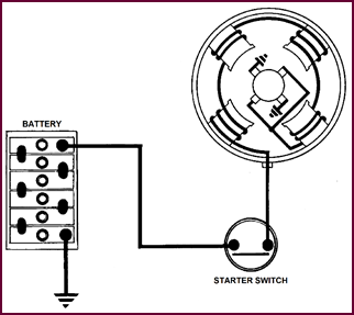 The Complete
Electrical Circuit
The Complete
Electrical Circuit
Figure 24. The complete electrical
circuit.
In Figure 24, you see the starter
motor in circuit. The ex-ternal cable layout to the motor is shown, basically as
it would appear on a vehicle. The two components that are necessary are the
battery to supply the current and a switch to control the current supply to the
starter motor.
We have used a plain series machine in this
circuit, but it could be directly replaced by the series-parallel type.
Let us follow the circuit through,
commencing at the battery. We shall assume that the starter switch is closed.
A heavy cable connects the battery to one
side of the switch. The circuit continues across the contacts in the closed
position to the starter motor. It carries on round the four field coils in
series via the two insulated brushes to the armature. The pair of earth brushes
complete the circuit through the metal of the starter end bracket to the body
of the machine, which is bolted to the vehicle chassis or earth. This earth connects
with the battery earth terminal which is also strapped to the chassis.
 Torque
Figure 25. Explanation of the term
torque.
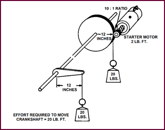
Let us now take a closer look at the
expression 'Torque', which is the term used to define the turning movement or
effort produced by the starter motor.
A simple illustration will suffice to
acquaint you with the significance of the term.
If a force of 20 lbs. is applied to an
engine crankshaft through a leverage of 12 inches, the turning effort pro-duced
would be:
20 x 1:20 lbs. ft.
The same unit of measurement i.e. lbs. ft.
is used to express the turning effort developed by the starter motor when this
effort is applied to the engine crankshaft via the flywheel.
But, to produce an equivalent 20 lbs. ft.
torque at the engine crankshaft, the torque developed by the starter motor need
only be 2 lbs. ft., due to the mechanical aid of gear ratio of 10 : 1 between flywheel
and pinion.
 Lock Torque
Test
Lock Torque
Test
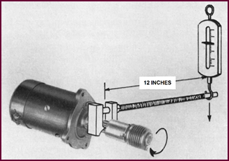
Figure 26. Principle of the starter
torque test.
For test purposes, the torque produced by
the starter motor is measured with the starter taking current, but with the
armature shaft prevented from turning by a brake or clamp. The torque produced by
the starter when trying to turn against this brake is termed the 'Lock Torque'
and the test, quite logically, the 'Lock Torque Test'.
The measurement can be taken directly from
the arm-ature shaft or via a test-bench flywheel.
Battery
Capacity:
Its Importance In Relation To Engine Starting
In connection with the performance of the
starter motor, the importance of the battery must not be forgotten. Owing to
the very heavy current taken by the starter, there is quite an appreciable drop
in the battery voltage. The performance of the starter motor is therefore
largely dependent upon the size of the battery employed. A battery of ample
capacity is essential, otherwise the heavy discharge current will result in an
excessive volt-age drop which will limit the current available for the starter
motor, and in turn reduce the torque developed.
In this case, you see, we need a current of
275 amps. at 9-volts. The top battery won't give us this current; it can only
supply a maximum of 200 amps at this voltage. The other, larger capacity
battery will, with some to spare.
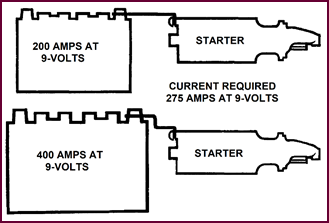 Figure 27. Battery size requirement
comparison.
Figure 27. Battery size requirement
comparison.
The
Transmission Of The Turning Effort
 We must now show how the torque or
turning movement we have produced is transmitted to the vehicle engine; in
other words how the motor we have created becomes a starter motor.
We must now show how the torque or
turning movement we have produced is transmitted to the vehicle engine; in
other words how the motor we have created becomes a starter motor.
Figure 28. An example of a starter drive
arrangement.
Figure 28
shows you one of the many different types of starter drives. The pinion engages
with the flywheel, thus transferring the turning movement of the starter
armature shaft to the engine crankshaft.
Pinion And
Flywheel
 The pinion and flywheel can be seen in
this picture. The pinion to flywheel ratios vary usually from 9:1 to 14:1 but
are generally in the order of 9 or 10:1 on modern vehicles.
The pinion and flywheel can be seen in
this picture. The pinion to flywheel ratios vary usually from 9:1 to 14:1 but
are generally in the order of 9 or 10:1 on modern vehicles.
Figure 29. Showing starter pinion and
flywheel ring gear.
Cranking Speeds
In order to turn this flywheel at
sufficient speed to start the engine, a minimum 'cranking speed' of approximately
90 to a 100 r.p.m. is required. Cranking speeds are usually stated as 'cold
cranking speed' or 'hot cranking speed'. Obviously the effort required to turn
over a warm engine is far less than that for a cold engine, when the oil is
thick.
Breakaway
Torque
We must discuss one further term in
connection with starter motors and engine starting in general:
'Breakaway Torque' – the torque required to
move the engine from rest, that is to overcome friction, oil viscosity,
compression etc.
This breakaway torque is usually of short
duration, but it is evident that it represents the maximum turning effort the
starter motor must produce. Fortunately, however, the main characteristic of the
series motor is that it produces its maximum torque at the beginning of the
starting operation, that is when it is most needed.
Graph – Torque,
Speed, Current
Here we have
plotted 'Torque' and 'Current' against speed in R.P.M.
and indicated the starter terminal voltage.
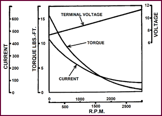 You can see that the torque curve falls
from the maximum as the speed of the starter increases. It is this character-istic
which renders the series type of motor particularly suitable as an engine
starting motor.
You can see that the torque curve falls
from the maximum as the speed of the starter increases. It is this character-istic
which renders the series type of motor particularly suitable as an engine
starting motor.
Figure 30. Torque, speed, current
curves.
And furthermore, when the starter armature rotates
in the magnetic field, a voltage known as a 'back EMF' will be induced into the windings, which is proportional
to the speed of rotation. As this induced voltage is in an opposite
direc-tion to the supply voltage, it opposes
the latter. The current drawn from the battery therefore decreases as
the speed of the motor increases. You can see this from the current curve. The
starter terminal voltage will rise as the load decreases; and as the current
drops, so the torque de-creases; in other words, the least torque is produced
when the starting load is at a minimum.
One further characteristic of the series
motor is that its speed varies appreciably with load variation. Particularly is
this so with light loads, where the speed increases at a very rapid rate, so
that under no-load conditions the motor may attain really dangerous speeds. These
series motors should therefore never be allowed to run con-tinuously without
load.
PART TWO –
LUCAS STARTERS'
SYMBOLS AND MODEL INTERPRETATION
Current
Production Starters
Having discussed the theory of the starter
motor and explained several terms essential to the understanding of engine
starting, we shall now show you the practical application of all this theory,
dealing with the various types of Lucas Starters.
The power developed by our Light Car
Starter Motors today may be as high as 22 lbs. ft. Lock Torque, (or the
equivalent of 1½ B.H.P. at 1,000 r.p.m.). And the currents required to produce
such high torques can be in the order of 400 amperes or more.
Symbols
We produce three main types of starters:
the M35G.; the M418G., and the M45G.
The letter 'M' means in all cases starter
motor: the number refers to the diameter of the yoke, and indicates that it is
either 3·5", 4·125" or 4·5" in diameter. The final letter, as
you can see, usually indicates some special feature, either a particular type
of end bracket, a water-proofed machine etc.
Starter Symbols
Prefix M – Starter Motor
35 – 3½" Diameter
418 – 4⅛" Diameter
45 – 4½" Diameter
Suffix A – Pressed Metal C.E. Bracket
G – Die Cast C.E. Bracket
L – Long Type Machine
w – Waterproofed
The M35G. Starter
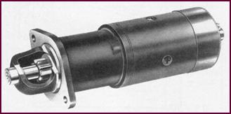 This machine is a 4-pole, 4-brush, series
motor. It is produced either with the field coils wired in series or in
series-parallel. The plain series arrangement is usually employed for the 12-volt
machine, and the series-parallel for the 6-volt.
This machine is a 4-pole, 4-brush, series
motor. It is produced either with the field coils wired in series or in
series-parallel. The plain series arrangement is usually employed for the 12-volt
machine, and the series-parallel for the 6-volt.
Figure 31. Illustration of the M 35 G
starter motor.
The highest torque available from these 3½"
models is approximately 9·3 lbs. ft. Lock Torque at 380 amps. for the 12-volt
machine, and 6 lbs. ft. at 400 amps. for the 6-volt machine.
The M418G. And
M45G. Starters
Both these starters are 4-pole, 4-brush
machines with series-parallel fields. This arrangement of the field coils produces an overall increase in the torque developed.
The maximum Lock Torque figures for the M4l8G. type are:
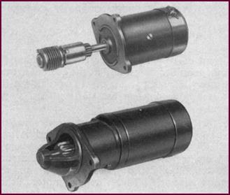 17 lbs. ft. at 450 amps. for the 12-volt
machine and 9·25 lbs. ft. at 520 amps. for the 6-volt machine.
17 lbs. ft. at 450 amps. for the 12-volt
machine and 9·25 lbs. ft. at 520 amps. for the 6-volt machine.
Figure 32. Upper – M418G starter; lower
– M45G starter.
For the M45G. i.e. the 4½ inch machine,
the 12-volt range have a maximum Lock Torque of 22 lbs. ft. at 440 amps. and
the 6-volt range of 14 lbs. ft. at 550 ampéres.
In the next part we shall deal with the
different types of drives used with the above range of starter motors.
PART THREE –
STARTER DRIVES
Main Types Of
Starter Drive
We have told you how the turning effort
produced by the starter motor is transmitted to the engine flywheel by means of
a starter drive and we shall now classify the various types, explaining the differences,
both in con-struction and operation.
As far as the method of engagement is
concerned, starter drives fall into three main groups: the inertia or 'crash'
type, the pre-engaged type and the axial type.
For our purposes we shall deal mainly with
the inertia drive, this being the type normally employed for cars and light commercial
vehicles.
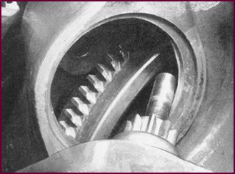
The 'Inertia'
Or Crash Type Drive
Here you see a simple 'Inertia' or
'Crash-Type' drive. As the starter armature rotates, quickly reaching a high
speed, the pinion, lagging behind the movement due 1o inertia, slides along a
screwed sleeve into mesh with the flywheel teeth.
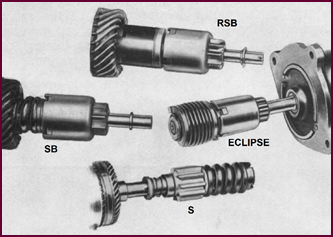 Figure 33. The Lucas inertia type of
drive.
Figure 33. The Lucas inertia type of
drive.
The pinion and sleeve assembly is carried
on splines on the armature shaft, this arrangement allowing the sleeve to move
along the shaft against the action of a heavy compression spring, thus
absorbing the initial shock of engagement. The pinion is thrown back into the
diseng-aged position when the speed of the flywheel is relatively greater than
that of the pinion, that is when the engine speed exceeds the motor speed.
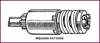
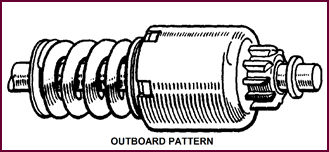
Inboard And
Outboard Operation
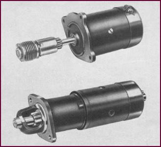 According to the method of mounting, the
pinion may be arranged to move towards the starter motor to engage the flywheel
or away from the motor. The former arrangement is known as the inboard drive –
that's the one you see at the top; the latter is the outboard drive.
According to the method of mounting, the
pinion may be arranged to move towards the starter motor to engage the flywheel
or away from the motor. The former arrangement is known as the inboard drive –
that's the one you see at the top; the latter is the outboard drive.
Figure 34. Inboard (upper) and outboard
(lower) types of starter drive units.
You will observe in the bottom picture that
a special housing is necessary for outboard drives in order that an additional
bearing can be provided to support the outer end of the shaft.
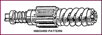
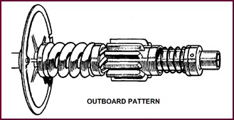
Four Main Types
Of Starter Drives
Lucas make four main types of inertia drive
:
The S, SB, the RSB (rubber coupling) and
the Eclipse, with inboard and outboard models of each type. 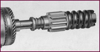 We shall now examine each type
individually.
We shall now examine each type
individually.
Figure 35. Main types of drives on Lucas
starter motors.
The 'S' Type
Drive
 The shock load is here absorbed by the
heavy compres-sion spring. A light retaining spring prevents the pinion from
being vibrated into contact with the flywheel when the engine is running.
The shock load is here absorbed by the
heavy compres-sion spring. A light retaining spring prevents the pinion from
being vibrated into contact with the flywheel when the engine is running.
Figure 36. An example of Lucas 'S' type
inboard drive.
 The pinion of the inboard drive moves in
towards the starter motor, that is from right to left in this picture.
The pinion of the inboard drive moves in
towards the starter motor, that is from right to left in this picture.
Figure 37. An example of Lucas 'S' type
outboard drive.
With the outboard drive the pinion moves
outwards from the motor towards the end of the shaft.
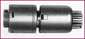
 The 'SB' Type
Drive
The 'SB' Type
Drive
Figure 38. An example of Lucas 'SB'
inboard drive.
Figure 39. An example of Lucas 'SB'
outboard drive.
The 'SB' drive is a later version of the 'S'
type you have just seen. The pinion is here carried on a barrel type assembly
which is mounted on a screwed sleeve. This sleeve is carried on splines on the
armature shaft and moves along the shaft against the action of a compres-sion
spring. The pinion retaining spring is incorporated in the barrel drive.
Rubber Coupling
Drives
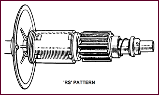 There are three models of this type, the 'RS'
and 'RSB' being for outboard meshing, and the 'RE' for inboard and outboard.
There are three models of this type, the 'RS'
and 'RSB' being for outboard meshing, and the 'RE' for inboard and outboard.
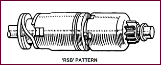 Figure 40. Above, Lucas 'RS' pattern drive.
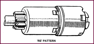 Figure 41. Above, Lucas 'RSB' pattern
drive.
Figure 41. Above, Lucas 'RSB' pattern
drive.
Figure 42. Above, Lucas 'RE' pattern
drive.
All these types of drive embody a
combination of rubber torsion member and friction clutch. These control the
torque transmitted from the starter to the engine flywheel and dissipate the
energy developed in the rotating armat-ure of the starter at the moment when
the pinion engages with the flywheel.
They also embody an overload release which functions
in the case of extreme stress, such as may occur when the starter is
inadvertently meshed into a flywheel rotating in the reverse direction.
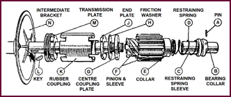
The 'RS' Type
Drive
When the starter is energised, the torque
is transmitted to the pinion by two paths. One, from the transmission plate M, Figure
41, which is keyed on to the shaft, via the outer sleeve of the
rubber coupling, K, and through the friction washer, H, to the screwed sleeve. The
other path: from the transmission plate, M, to the outer sleeve of the rubber
coupling, through the rubber to the inner sleeve and then via the centre coupling
plate, G, to the screwed sleeve and hence to the pinion. The rubber limits the
total torque which the drive transmits and, because the rubber is bonded to the
inner sleeve, slipping can only occur be-tween the rubber bush and the outer
sleeve of the coupling. This slipping acts as a safety device against overload.
Under normal conditions, the rubber will act as a spring and there will be no
slip.
Figure 43. Components of the Lucas RS
type drive.
In all these drives, a pinion restraining
spring D, is fitted, and this prevents the pinion from vibrating into mesh when
the engine is running.
 This particular drive is the RS pattern,
but the principle of operation applies equally well to the other two types, the
RSB and the RE.
This particular drive is the RS pattern,
but the principle of operation applies equally well to the other two types, the
RSB and the RE.
 'RS' Drive –
Outboard
'RS' Drive –
Outboard
Figure 44. Lucas RS drive of outboard
type.
This is another picture of the RS drive and
you'll notice that it is for outboard meshing.
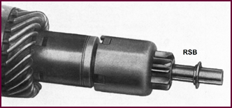 'RSB' Drive
Figure 45. Lucas RSB type drive.
The RSB drive is again an outboard type. In
this drive, a pinion and barrel assembly is used.
 'RE' Drive
Figure 46. Lucas RE type drive.
The RE drive is the only one of the rubber
coupling types built for both inboard and outboard operation. Again you'll
remark that the pinion and barrel assembly is used.
'Eclipse' Drive
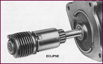 The last main group of drives we have to
deal with contains the 'Eclipse' pattern. Here you have a general view of this
drive, which is used for both inboard and outboard operation.
The last main group of drives we have to
deal with contains the 'Eclipse' pattern. Here you have a general view of this
drive, which is used for both inboard and outboard operation.
Figure 47. An example of the Lucas
Eclipse type drive.
Basically it is a modified form of the 'RE'
drive, a main torsion spring, however, taking the place of the rubber.
'Eclipse'
Pattern Drive – Exploded View
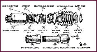 A meshing spring 'A' (top left) and
friction washer, R, (bottom centre) allow for slip under overload conditions.
A meshing spring 'A' (top left) and
friction washer, R, (bottom centre) allow for slip under overload conditions.
Figure 48. Lucas Eclipse drive –
exploded view.
The pinion is carried on a barrel type
assembly which is mounted on a screwed sleeve, M, (bottom left). This sleeve is
carried on a centre sleeve, N, and is secured to the armature shaft by means of
a pin and key, P, and O. The barrel assembly
is so arranged that it can move along the shaft against the action of
the 'torsion' spring, K, to reduce the shock loading at the moment of
engagement. A pinion restraining spring, C, is incorporated in the drive.
Pinion
Engagement
Before leaving the subject of starter
drives, some refer-ence should be made to the difficulties which sometimes
arise with starter engagement.
You can be assured that before any engine
goes into general production, the engine manufacturer has satis-fied himself
that the Lucas starter which he has selected – generally in collaboration with
our Sales Engineers – is suitable for that engine.
It sometimes happens however, that the
assembly toler-ances for instance, which finally determine the position of the
leading edge of the flywheel teeth in relation to the starter motor pinion, do
not work out quite as expected, resulting in starting troubles in service. The
starter pinion may have to travel too far, thus developing a high speed before
engaging the flywheel teeth, with the result that 'milling' or 'chipping' of
the teeth takes place.
Comparing A New
And Worn Pinion
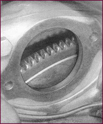
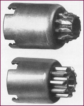 You can see in this picture how badly the
teeth of one of the pinions have been damaged.
You can see in this picture how badly the
teeth of one of the pinions have been damaged.
Figure 49. Starter pinions, upper is
worn, lower is new.
 Flywheel Ring
– Normal Wear
Flywheel Ring
– Normal Wear
Figure 50. Flywheel ring gear, showing
normal wear.
These flywheel teeth show no more than
normal wear after prolonged service.
Out Of Mesh
Clearance
 If the distance between pinion and
flywheel is correct, no abnormal wear of the teeth takes place, the pinion
sliding into mesh with little preliminary rotary movement. This distance, when
the pinion is in the disengaged position, is called the 'out-of-mesh clearance.
If the distance between pinion and
flywheel is correct, no abnormal wear of the teeth takes place, the pinion
sliding into mesh with little preliminary rotary movement. This distance, when
the pinion is in the disengaged position, is called the 'out-of-mesh clearance.
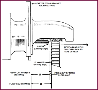
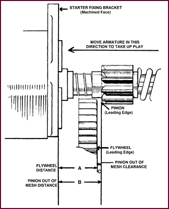 Figure 51.
Showing out of mesh clearance, outboard drive.
Figure 51.
Showing out of mesh clearance, outboard drive.
Figure 52. Showing out of mesh
clearance, inboard drive.
In Figures 51 and 52, we show
both an outboard and in-board type arrangement here, the difference between measurements,
A and B, being in each case the out-of-mesh clearance.
Measuring Out
Of Mesh Clearance
The method of measuring the clearance is
shown in Figure 53.
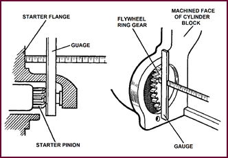 First take the dimension in the left hand
picture, that is the distance between the starter – flange face and the leading
edge of the pinion teeth.
First take the dimension in the left hand
picture, that is the distance between the starter – flange face and the leading
edge of the pinion teeth.
Figure 53. How to measure out of mesh
clearance.
Then, as in the picture on the right,
measure the distance from the machined face on the clutch housing to the
fly-wheel ring gear. A properly calibrated depth gauge should be used to ensure
accurate measurement.
The first measurement should then be
subtracted from the second.
The correct clearances for the various
types of drive are:
Eclipse Type 1/16" to 3/16"
All other types 3/32" to 5/32"
Excessive
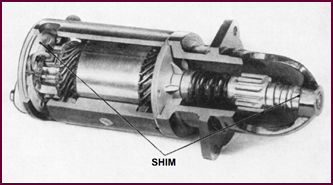
Armature End Float – Shimming
 Even if the clearance was originally
correct, if, in the course of service, excessive end-float is allowed to de-velop
in the armature shaft, the out-of-mesh clearance may be sufficiently increased
to cause trouble.
Even if the clearance was originally
correct, if, in the course of service, excessive end-float is allowed to de-velop
in the armature shaft, the out-of-mesh clearance may be sufficiently increased
to cause trouble.
Figure 54. Shim adjustment of armature.
If noisy starter operation is experienced,
the armature end-float of the starter should be checked, and if found to be
excessive, shims should be inserted to take up the play. In the case of
outboard starters, shims should be inserted at both the commutator and drive
ends. In the case of inboard machines, the drive end only is shimmed.
Ten-thousands (0·010) of an inch end float
is normal, but if more than 0·015", the out-of-mesh clearance may be
affected, and any excess should be taken up.
Faulty
Engagement And Disengagement
Faulty engagement as a general rule is the
result of allowing the screwed sleeve and pinion assembly to be-come rusty or
choked with grease or dirt and this may be easily rectified by a clean-up and
re-lubrication with a light machine oil. It is particularly important to use a
light machine oil under low temperature operating conditions when the motor's
acceleration may be reduced owing to the heavy current taken by the motor.
Other reasons for failure to engage may be
broken or distorted restraining springs, broken or contracted main springs,
faulty re-assembly of the complete drive after servicing, or incorrect
out-of-mesh clearances.
As far as faulty disengagement is
concerned, we will con-tent ourselves with listing the likely causes. Sticking
of the pinion in mesh with the flywheel can be caused by:
1) Bent armature.
2) Worn screwed sleeve, which causes the pinion to stick along the
thread.
3) Dirty or rusty condition of the sleeve and pinion.
4) Slack drive assembly, usually due to the weakening of the
compression spring.
5) Incorrectly adjusted switch operating cable.
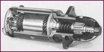
Assembly And
Lubrication Of Drives
 These other points should not be
overlooked if the mech-anical side of the starting operation is in any way
suspect.
These other points should not be
overlooked if the mech-anical side of the starting operation is in any way
suspect.
Figure 55. Section showing starter motor
drive.
First, the assembly of the drive. The unit
may have been dismantled and reassembled incorrectly, in which case the best
results can hardly be expected. And secondly the drive may be dry or dirty. A clean
drive, lightly oiled, will give efficient operation.
PART FOUR –
SERVICE TESTING ON VEHICLE
Starter
Circuits
Having dealt mainly with the mechanical
aspects of starting and starter motors, we shall now discuss the electrical side,
showing you various starter circuits and finishing with a comprehensive series
of tests for proving the electrical system.
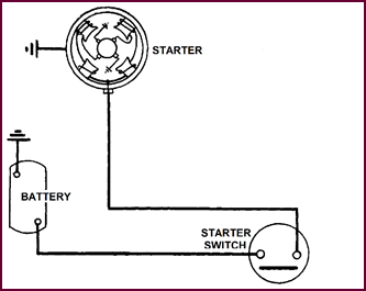 Fundamentally the starter circuit is
extremely simple as you can see, consisting of the feed wire from the battery
to the starter motor, the circuit being controlled by a switch. The return path
is via the chassis.
Fundamentally the starter circuit is
extremely simple as you can see, consisting of the feed wire from the battery
to the starter motor, the circuit being controlled by a switch. The return path
is via the chassis.
Figure 56.
Diagram of basic starter motor electrical circuit.
Lucas produce several types of starter
switch. The one represented here is the simple manually-operated pull or push
type.
Manually
Operated Starter Switches
Several examples of the manually operated
switch are shown here.
Figure 57. Above, right, a selection of
Lucas starter motor switches.
Each type, of course, is capable of passing
the heavy current required by the starter motor, without voltage loss.
The effective life of any of them depends
mainly on two factors: that the contact should be clean and positive; and that
the break should be quick, with sufficient travel.
Switch
Adjustment
Where the switch is operated by Bowden
Cable, it is extremely important that the pull is correctly adjusted. Otherwise
excessive burning of the contacts takes place, with resultant loss of starter
performance. There is a danger also, that with a too close adjustment of the switch
contacts, the starter motor may be vibrated into operat-ion. There should be
about ⅛" free movement in
the cable before the switch lever is moved. See Figure 58.
The push type switches are spring-loaded
and require no adjustment.
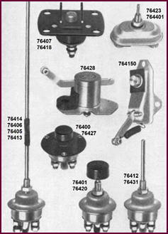
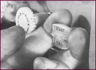 Figure 58. A Lucas pull type starter
switch.
Figure 58. A Lucas pull type starter
switch.
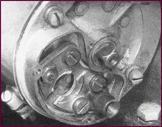 'G' Type End
Bracket
'G' Type End
Bracket
Figure 59.
The 'G' type end bracket, showing the contacts.
For starter motors with inbuilt manual
switch, where this 'G' type end bracket is used, the two fixed contacts, each
with two cheese head screws, must be faced to ensure correct alignment for the
moving contact.
End Bracket
Blanking Plate
 We now mount the starter switch
separately, thus enabl-ing us to produce a standard type of end bracket. Many
starters with 'G' type end brackets are still, however, in service and for
these a 'blanking-off' plate is used which carries a disc contact to bridge the
two fixed contacts.
We now mount the starter switch
separately, thus enabl-ing us to produce a standard type of end bracket. Many
starters with 'G' type end brackets are still, however, in service and for
these a 'blanking-off' plate is used which carries a disc contact to bridge the
two fixed contacts.
Figure 60. The blanking plate in
position on end bracket.
This
arrangement enables the separately mounted switch,
usually of the solenoid type, to be used.
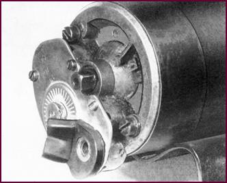
Starter
Solenoid Switch
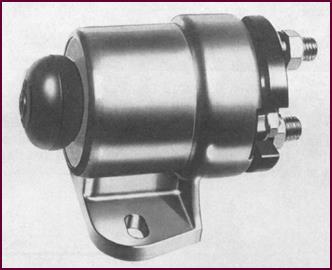
The electrically operated switch or
solenoid is shown here in Figure 61.
 It contains the main starter contacts
which are closed magnetically when the relay winding inside the switch is
energised – that is when the starter push on the dash-board is pressed.
It contains the main starter contacts
which are closed magnetically when the relay winding inside the switch is
energised – that is when the starter push on the dash-board is pressed.
Figure 61. A typical Lucas starter
solenoid switch.
One end of this winding is connected to the
smallest of the three terminals, and the other end to the metal case, which is
earthed when the solenoid is bolted to the metal-work of the vehicle.
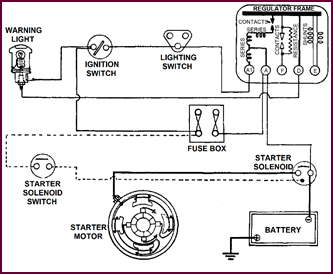
Circuit For
Solenoid Operated Starter
In the normal circuit, the feed to the
solenoid operating push is taken effectively from the ignition switch; A3 on
the fuse board being used here only as a junction point. You'll notice there is
no fuse in circuit. The cable from the negative of the battery is taken direct
to one of the main solenoid terminals, the other main terminal being con-nected
to the starter motor. The circuit is again completed via the starter and
battery earths.
Figure 62. Circuit diagram for solenoid
operated starter.
Testing The
Starter System
From the earlier parts of our talk you may
have gained the impression that starting troubles are mainly mechan-ical in
origin – far from it. Trouble may often be traced to electrical causes: either
to a faulty battery, a bad connect-ion in the circuit or to a poor contact at
the switch. It should never be assumed when faced with total failure or
sluggish operation of a starter motor, that the fault lies necessarily with the
motor itself.
It is
therefore imperative that a systematic series of checks
be first carried out on the electrical circuit so that the fault may be
localised.
Checking Procedure
We shall tackle the job in this order:
1) Battery check.
2) Voltage at the Battery.
3) Voltage at the Starter.
4) Voltage drop on main Line.
5) Checking starter switch.
6) Voltage drop on earth Line.
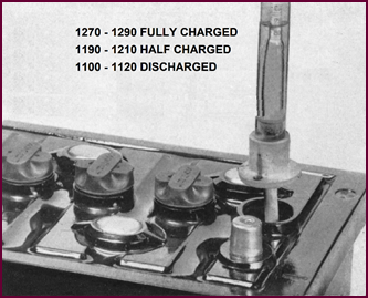 Battery Check – Hydrometer Test
Figure 63. Carrying out the hydrometer
test on battery.
The hydrometer should show an evenly
charged battery, that is, no great variation in cell readings, and at least a
half-charged condition.
Battery Check –
Heavy Discharge Test
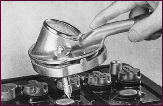 As a further check for the battery, a
heavy discharge tester should be applied for approximately 15 seconds to each
cell.
As a further check for the battery, a
heavy discharge tester should be applied for approximately 15 seconds to each
cell.
Figure 64. The heavy discharge test on
each battery cell.
Steady readings of approximately 1·5-v. per
cell indicate a serviceable battery. A falling reading will be obtained from
any cell which is defective.
We have thus made sure that the battery is
at least cap-able of giving the heavy current required by the starter motor.
Voltage At The
Battery Terminals
And now, the rest of the circuit. The first
check will give us the working voltage or pressure at the battery. The
voltmeter is connected between positive and negative terminals.
When the starter is operated on a cold
engine, the readings should not fall below 10-volts for the 12-volt system and
4·5-volts for the 6-volt system.
Figure 65. Checking the voltage at the
battery terminals.
 Voltage At
Starter Motor Terminal
Voltage At
Starter Motor Terminal
Figure 66. Voltage test at starter motor
terminal.
Assuming the voltage at the battery to be
in order, next check the voltage at the starter terminal. This should be no
more than 0·5-volt lower than the previous reading. The voltmeter is
connected between the starter terminal and the starter yoke. In this
photograph, the bottom volt-meter lead should NOT be connected where it is –
there may be a bad connection between the engine block and the starter yoke
(pinion end bracket) itself.
If a low reading had been obtained, both at
the battery in the previous test and at the starter terminal, the motor is
taking too much current, and the trouble will be found in the starter motor
itself.
A good voltage at the battery and a poor
voltage at the starter i.e. a considerable voltage drop, indicates a high
resistance somewhere in the circuit.
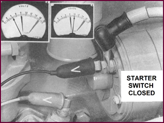
Voltage Drop On
The Insulated Line
For our next test, we connect the voltmeter
between the starter terminal and the main battery post to check the voltage
drop on the insulated or feed line.
Before the starter switch is closed,
battery voltage should be registered. But on closing the switch, the reading
should fall to zero; but readings of up to 0·5-volt are permissible in service.
If a higher voltage is registered, a 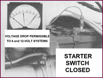 high resistance point somewhere along the
line is indicat-
high resistance point somewhere along the
line is indicat-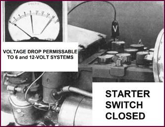 ed. The most likely place is at the switch
contacts.
ed. The most likely place is at the switch
contacts.
Figure 67. Voltage drop test on the
insulated line.
 Checking The
Switch Contacts
Checking The
Switch Contacts
Figure 68. Checking the switch contacts.
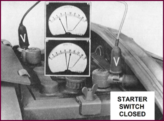
The contacts can be checked by connecting a
voltmeter across them and closing the switch. The reading of bat-tery voltage
should fall immediately to zero or within 0·5-volt of zero.
If the reading
is within this limit, the high resistance deduced in
the last test must be due either to a loose or corroded terminal, either at the
battery or starter switch, or at the starter motor. All of these points can
easily be checked by a visual examination.
Voltage On
Earth Line
In this last test, we are checking for
voltage losses caused by a high resistance point on the earth return side of
the circuit.
The voltmeter is connected between the
battery earth terminal and the starter yoke. If the earth line is in order, the
voltage drop when the starter is operated will be zero.
In service, a voltage drop of 0·5 volt is
permissible.
Figure 69. Checking voltage on earth
line.
The Earth
Connection
 If a substantially higher reading is
obtained, all earth con-nections in the starter circuit must be checked.
If a substantially higher reading is
obtained, all earth con-nections in the starter circuit must be checked.
Figure 70. The earth return connection.
Using the voltmeter as we have shown, each connection
must be proved electrically sound. The most frequent cause of voltage drop on
the earth line is a bad connect-ion where the lug is earthed. Make sure that
any such connection is clean and tight. Be particularly wary if the vehicle has
just been repaired or painted; the connection may have been disturbed.
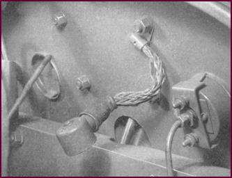
The Bonding
Strip
Another likely trouble spot is at the
'bonding strip' bet-ween the engine block and the chassis. Remember that modern
engines are rubber-mounted, the only good elec-trical connection to the chassis
often being made by means of this strip.
Sluggish operation of the starter and
sometimes complete failure can be caused by such a fault, or by a combination
of minor losses at different points which produce in one circuit a sufficiently
serious voltage drop to affect the performance of the starter motor.
We hope we have proved our point: do not
suspect the starter before you have tested its electrical supply. Like most of
us, it won't work if it's not fed properly.
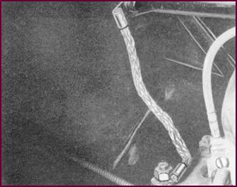 Figure 71. The bonding strip (earth
strap) must be sound.
Figure 71. The bonding strip (earth
strap) must be sound.
SUPPLEMENT ONE – THE LUCAS M45G PRE-ENGAGED STARTER
General View – Manually Operated Pre-Engaged Starter
 The majority of Lucas starters are
equipped with the inertia or 'crash-type' drive. In this arrangement, the
starter motor is first energised, the revolving armature then forcing the
pinion along a screwed sleeve into mesh with the engine flywheel.
The majority of Lucas starters are
equipped with the inertia or 'crash-type' drive. In this arrangement, the
starter motor is first energised, the revolving armature then forcing the
pinion along a screwed sleeve into mesh with the engine flywheel.
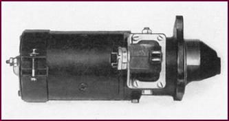
Figure 72. A Lucas pre-engaged starter
motor.
The pre-engaged starter we feature here
employs a different method of engagement: as its name implies, the pinion is
actually in mesh with the flywheel ring gear prior to the torque being applied.
This type of engagement is more suitable
for heavier engines of the diesel type, where large flywheels, high compression
ratios and generally higher cranking speeds are usual. A normal inertia drive
would quickly be dam-aged when operating under these conditions; the mesh-ing
impact of the driven-pinion on a comparatively solid flywheel would be far too great
to give an adequate service life for the starter motor.
The
pre-engaged starter is basically similar to the Standard M45G motor, with a different drive assembly, and a pilot switch.
Cross Section
Of Starter And Fly-Wheel
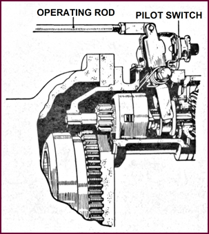 The position of the pilot switch in
relation to the drive assembly is visible in Figure 73.
The position of the pilot switch in
relation to the drive assembly is visible in Figure 73.
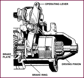
Figure 73. Sectioned view of starter and
bell-housing, showing starter operating rod in position.
When the starter operating rod is moved
into the starting position, the operating lever attached to the end of it
slides the pinion along the armature shaft into mesh with the flywheel ring
gear. In Figure 70, the movement is just beginning. When the pinion has travelled
the correct dist-ance, the operating lever will close the pilot switch
contacts. This completes the circuit for the energising winding of the starter solenoid, thus closing the main starter
contacts. The starter armature revolves, transmitting the cranking torque via the pre-engaged pinion to the
fly wheel.
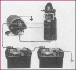 The
Components Connected In Circuit
The
Components Connected In Circuit
Figure
74. The components that make up the circuit.
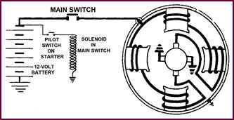
We have connected the components in circuit
here to give a general idea of the layout. Note the pilot switch on the
starter motor.
We will assume
that the starter pinion has just been pushed into mesh
with the flywheel. The pilot switch contacts will thus be made and the
circuit for the energising winding of the
solenoid completed. Commencing at the battery earth, this circuit is as follows:
through the two 6-volt batteries to one of the main solenoid terminals which is
connected to one side of the pilot switch. Current passes across the switch
contacts to the small solenoid terminal. The energising winding is connected
between this terminal and the case which, as you can see, is earthed. The
circuit is thus returned to the battery.
When the solenoid operates, the plunger
closes the main contacts in the starter supply line, thus energising the
starter in the normal way.
 The Wiring
Circuit
The Wiring
Circuit
 The internal and external connections can
be seen from this circuit.
The internal and external connections can
be seen from this circuit.
Figure 75. Wiring circuit for a
pre-engaged starter motor.
The study of this diagram will be
simplified if you divide the circuit into two: first, the relay operating circuit;
secondly, the main current circuit.
The Pilot
Switch And Rubber Shroud
This close-up shows the pilot switch with
its two grub screw connections, at left. The switch plunger is actuated by the
operating lever when the starter rod is moved.
Figure 76. The pilot switch and the
rubber cover for the pinion engagement mechanism.
The switch assembly is fixed to the starter
body by four set screws, which also serve to fasten the water-proofing rubber
shroud in position.
The switch bracket is slotted so as to
allow adjustment of the switch in relation to the operating lever. We shall be referring
to this adjustment more fully later on.
The Armature
Brake
Let us now make a more detailed examination
of the mechanical operation of this starter.
In the rest position, the bottom of the operating
lever holds a brake plate hard against a brake lining. You can see the coiled
springs which provide the tension. The plate is carried on the splines of the armature
shaft and the brake lining riveted to the intermediate bracket. The armature is
thus prevented from rotating when the plate and lining come into contact.
Figure 77. Sectioned view of the
armature brake system.
Consider for instance a case where the
starter is oper-ated and the engine fires, but then stops; the starter pinion
could possibly still be revolving when it was again meshed into the flywheel.
The coiled springs prevent this by returning the operating lever to the rest
position and in so doing, a braking effect is applied to the armature.
 The Operating
Lever
The Operating
Lever
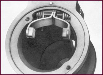
Figure 78. The operating lever.
 The stirrup shaped end of the operating
lever is visible here so are the coiled springs holding it under tension. The
two toggles actually form the bearing member that acts on the brake plate.
The stirrup shaped end of the operating
lever is visible here so are the coiled springs holding it under tension. The
two toggles actually form the bearing member that acts on the brake plate.
The Brake
Lining And Brake Plate
 And here you see, on the left, the brake
lining attached to the starter intermediate bracket.
And here you see, on the left, the brake
lining attached to the starter intermediate bracket.
Figure 79. Components that make up the
armature brake.
On the right, we have photographed the
brake plate in position at the end of the drive assembly.
The Compression
Spring
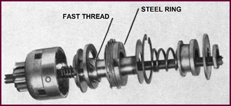
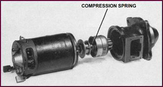 The next feature of the drive assembly we
wish to discuss is the compression spring. This is situated immediately behind
the pinion and barrel assembly.
The next feature of the drive assembly we
wish to discuss is the compression spring. This is situated immediately behind
the pinion and barrel assembly.
Figure 80. The location of the
compression spring.
Usually, the pinion and flywheel mesh
without any difficulty, the teeth being chamfered at the leading edges to ease
the engagement. It can happen however that the teeth butt against one another –
this is known generally as 'tooth to tooth' engagement. When this occurs, the
pinion will not slide into mesh but remains tight against the flywheel teeth. Increased
pressure must be applied to the starter operating rod. This compresses the
heavy spring behind the pinion and barrel, the compression continuing until the
pilot switch contacts are closed by the operating lever. The spring can be more
clearly seen in the exploded view in Figure 81. The armature then begins
to turn and immediately the pinion is sprung into mesh.
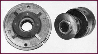
The Clutch
A clutch mechanism is incorporated in the
drive to avoid overloading the starter. It is housed in the barrel of the
pinion and barrel assembly.
Immediately the armature begins to turn, a
heavy steel ring slides along a fast thread compressing the clutch plates and
transmitting the drive to the pinion and barrel.
Figure 81. The components that make up
the clutch.
If the pinion sticks in mesh and the
flywheel attempts to drive the starter motor, the steel compression ring
returns along the fast thread to the rest position,
leaving the clutch plates slack so that no drive can be transmitted
through them.
If, to take another case, the engine load
is too great, such as when the vehicle is in gear and the starter motor
attempts to turn over the engine, the clutch is arranged to slip, thus relieving
any abnormal strain on the motor. This slipping will also protect the starter
should the engine backfire. The clutch is set during manufacture to slip in the
driving direction at two to three times the normal full load torque and should
never normally need re-adjust-ment in service.
Pilot Switch
Adjustment
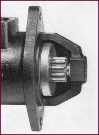
 You will appreciate that the position at
which the operat-ing lever closes the switch contacts is rather critical if the
pinion engagement is to be trouble free. Provision is therefore made for
adjusting the position of the switch plunger with respect to this lever.
You will appreciate that the position at
which the operat-ing lever closes the switch contacts is rather critical if the
pinion engagement is to be trouble free. Provision is therefore made for
adjusting the position of the switch plunger with respect to this lever.
Figure 82. Location of pilot switch
adjustment screws.
The four set
screws, visible in the picture secure the cover plate
and at the same time lock the adjusted switch in position.
The Adjusting
Holes
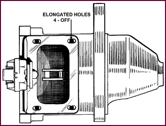 This shows the elongated adjusting holes
when the cover has been removed.
This shows the elongated adjusting holes
when the cover has been removed.
Figure 83. Elongated holes in pilot
switch mount plate.
Procedure For
Adjusting Switch
In service, the adjustment of the switch
should be carried out with the starter motor removed from the vehicle.
 The pilot switch should then be set to make electrical contact when
the leading edge of the starter pinion is from 1⅝" to 1¾",
as specified for individual vehicles, from the machined face of the drive end bracket.
The switch fixing screws should be temporarily loosened and the operating lever
pressed until the correct distance is reached. The switch can then be moved
forward so that the plunger engages with the operating lever.
The pilot switch should then be set to make electrical contact when
the leading edge of the starter pinion is from 1⅝" to 1¾",
as specified for individual vehicles, from the machined face of the drive end bracket.
The switch fixing screws should be temporarily loosened and the operating lever
pressed until the correct distance is reached. The switch can then be moved
forward so that the plunger engages with the operating lever.
We suggest that a test lamp and battery be
connected in series with the switch so as to facilitate finding the exact
position at which the plunger closes the contacts.
Figure 84. Adjusting the pilot switch
using pinion position.
When the motor is re-fitted, care must be
taken to see that the starter operating linkage on the vehicle is correct-ly
adjusted. There should be no slack in the movement; on the other hand, full
travel of the operating lever must be assured.
Maintenance
The pre-engaged starter needs no further
attention in service beyond that given to normal starter motors.
An inspection of the brush gear and
commutator, together with a check of the external electrical connections and
cabling, should form part of the normal maintenance.
Document Restorer's Note
Some of the electrical system tests can
be carried out with a multi-meter set to 'Continuity'. If a multi-meter is
used, be sure that the currents are not excessive.
In the diagnostic section, on Page 24,
mention is made of the 'Bonding Strip'. This component is now commonly
identified as an 'Earth Strap' – it is, emphatically, one of the most important
components in a vehicle's wiring system. Sound contact between the engine block
and the body/chassis structure is essential. Low quality earthing contacts at
this point can, on engagement of the starter, be the cause choke and throttle
cables to glow red hot, and could start outbreaks of fire.