The Battery
The Lead Acid Battery is simply a device
for storing electrical energy in a chemical form. This energy can be released
as electricity when needed.
Electrical energy is converted into
chemical energy during the charging of the battery.
During discharge, the energy stored in the
chemicals is released as electricity.
 Let us assume that our battery is discharged. By this we mean that
it is no longer capable of releasing electricity at a usable voltage or
pressure. The electro-chemical energy built up in the plates of each cell
during the charging process has been exhausted, and the chem-icals themselves,
instead of being active storers of electrical energy, have become inactive or inert.
Let us assume that our battery is discharged. By this we mean that
it is no longer capable of releasing electricity at a usable voltage or
pressure. The electro-chemical energy built up in the plates of each cell
during the charging process has been exhausted, and the chem-icals themselves,
instead of being active storers of electrical energy, have become inactive or inert.
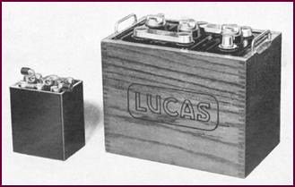
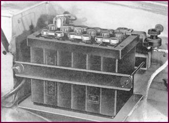
Figure
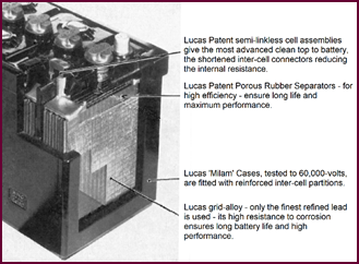
1. A typical Lucas Battery.
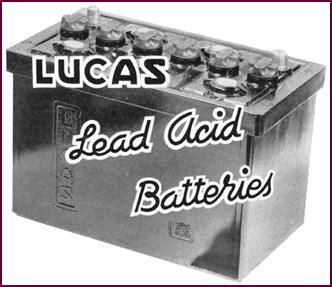
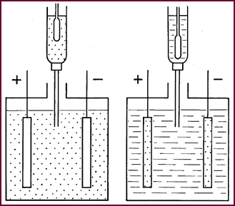
Cell On Charge
It is the function of the charging current
to break down these inactive chemicals on the battery plates, converting them
once more into active materials.
Both positive and negative plates in the
discharged con-dition are covered by a film of Lead Sulphate. During charging
this is converted, at the positive plate to active Lead Peroxide, at the
negative plate to active 'spongy lead'. The chemicals in this form are once
more capable of storing energy and delivering electricity. The sulphate from
the Lead Sulphate compound we've just broken down, cannot just disappear of
course: it combines with the electrolyte surrounding the plates, thus concen-trating
the dilute sulphuric acid solution.
At the same time, a mixture of gases is
given off from the battery. Hydrogen gas first appears in the form of bubbles
on the surface of the negative plate; oxygen gas is attracted in the same form
to the positive. The gases not used in the chemical reaction are then liberated
from the battery as the plates become fully charged.
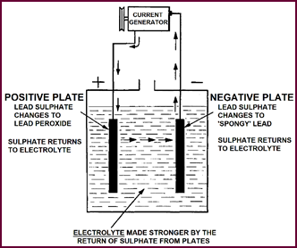
Figure 2. A cell on charge.
Discharge Of
Cell
 We can now regain the energy we have just put into the plates by
connecting them externally – a bulb is shown here completing the circuit. The electric
current thus re-leased flows through this circuit in the opposite direction to
that of the charging current, and the active materials of both positive and negative
plates gradually return to their inactive state, that is to inert lead
sulphate. The sulphate part of this compound comes of course from the sulphuric
acid of the electrolyte, thus leaving a weaker solution.
We can now regain the energy we have just put into the plates by
connecting them externally – a bulb is shown here completing the circuit. The electric
current thus re-leased flows through this circuit in the opposite direction to
that of the charging current, and the active materials of both positive and negative
plates gradually return to their inactive state, that is to inert lead
sulphate. The sulphate part of this compound comes of course from the sulphuric
acid of the electrolyte, thus leaving a weaker solution.
Figure
3. Discharge of a cell.
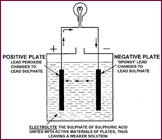
Charged And
Discharged Condition.
In this
diagram the sulphate group is represented by dots. You
can see that in the charged condition the sulphate has disappeared from the
plates and is concentrated in the electrolyte: in the discharged state the sulphate
group leaves the acid, becoming concentrated in the plates.
The electrolyte, which as you know, is a
solution of sul-phuric acid, is thus strong when the battery is charged and
weak when the battery is discharged. This gradual weakening of the electrolyte
is directly proportional to the amount of electricity delivered. If now we
could measure the amount of the sulphate group remaining in the electrolyte, we
should be able to judge how much elec-trical energy is left in the cell.
 The 'Hydrometer' is the instrument which enables us to take this
measurement, the measurement of density.
The 'Hydrometer' is the instrument which enables us to take this
measurement, the measurement of density.
Figure
4. Shows Charged and Discharged conditions.
 Density
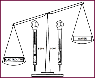
Figure 5.
Electrolyte for fully charged battery is 1·28 times
heavier than water.
Water is taken as the standard basic unit
and given a density of 1. Thus in effect we are weighing the elec-trolyte acid
against water. The denser or heavier the electrolyte, the higher will be the
hydrometer float, and consequently the reading. Thus for a fully-charged
battery, when the electrolyte is most concentrated, we shall have a hydrometer
reading of approximately 1280 – this is the everyday method of saying that our
acid is 1·280 times heavier than water. This density is usually referred to as
the SPECIFIC GRAVITY or 'S.G.' of the acid. And, as the battery cell loses its
energy in the form of electricity, so the hydrometer float will sink and the
density reading or 'S.G.' fall. You can see how, in the right of the picture,
the float has sunk just about as low as a float can sink.
Thus the hydrometer reflects fairly
accurately the state of charge of the cell, always providing that the cell is
in a normal condition.
Grids And
Plates
We have attempted to show you so far how
the Lead-Acid Battery stores and delivers electricity and in so doing we have
dealt a little with the chemical processes involved.
The basic idea of immersing two dissimilar
plates in a liquid capable of conducting an electric current still remains
today, but the method of constructing and assembling these plates has
progressed.
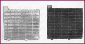 We start with a lead frame work or grid, strong enough mechanically
to withstand vibration; and conductive enough
electrically to offer little resistance to the passage of current. These grids
are filled with the active materials, and the plates so formed, built into
positive and negative groups.
We start with a lead frame work or grid, strong enough mechanically
to withstand vibration; and conductive enough
electrically to offer little resistance to the passage of current. These grids
are filled with the active materials, and the plates so formed, built into
positive and negative groups.
Figure 6. Typical grids and plates.
Groups Of
Plates And Separators
The plates of the positive and negative
groups are then interleaved and separators added between the plates, thus forming
a complete cell unit.
These separators are an essential part of
the battery, as their name implies they separate the negative from the positive
plates. An effective separator must: prevent short-circuits between the plates;
offer no resistance to the electro-chemical action and what's more be reason-ably
immune from the corrosive effect of the acid electrolyte.
All these demands have been met adequately
for many years by wood. The thin sheets used are suitably porous and
sufficiently resistant to acid of normal battery strength.
For all normal purposes, wood separators
give excellent service. An alternative now being widely used is the Porous
Rubber Separator as fitted in the latest models of Lucas Car and Motor Cycle
Batteries.
 These rubber separators have even greater mechanical strength and
decrease even further the possibility of internal short circuits.
These rubber separators have even greater mechanical strength and
decrease even further the possibility of internal short circuits.
For batteries, which are at times subjected
to severe vibration stresses, sheets of compressed glass fibre are now being
used as a further reinforcement of the separ-ation, in addition to the porous
rubber.
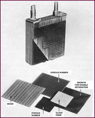 Ebonite is another material used, particularly for the heavier
batteries.
Ebonite is another material used, particularly for the heavier
batteries.
Figure
7. Battery cell components.
External
Features
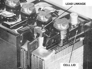
The Internal Construction of vehicle
batteries has devel-oped steadily 'unseen' but until quite recently external
features have not altered greatly until the introduction of the 'Linkless' type
of construction used on the GT range of batteries which are now so popular. One
of the advantages in this simple and workmanlike assembly, is the saving in
weight whilst retaining an ample cross section of metal to carry the maximum
currents required together with perfect sealing between the cells.
In the case of the larger commercial
batteries, used on heavy diesel and petrol engines, heavier inter-cell con-nectors
and posts are used to offer as little resistance as possible to the extremely
high currents. The lead linkages of these batteries are cored with copper.
We have also made modifications to the cell
lids of the car type battery. The overall result is an increase both in the
life and in the efficiency of the modern battery.
Figure 8. Illustrating the 'linkless'
type of construction.
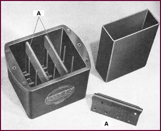
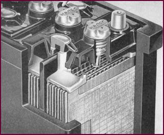
Containers
Lucas have developed a battery container
with the trade-name 'MILAM (made in Lucas Acid-Proof Material). This signifies
the moulded 'monobloc' container you see in the illustration. You will notice that
the inter-cell partitions are reinforced (A on illustration), a feature which
lessens the chance of current leakage between cells.
 There is one further point which must be mentioned in connection
with containers. The separators usually rest on ribs at the bottom of the
container, thus leaving space for sediment between the bottom of the plates and
the container. If this space were not present, sediment dis-lodged from the
plates would fall to the bottom of the container and cause internal short
circuits.
There is one further point which must be mentioned in connection
with containers. The separators usually rest on ribs at the bottom of the
container, thus leaving space for sediment between the bottom of the plates and
the container. If this space were not present, sediment dis-lodged from the
plates would fall to the bottom of the container and cause internal short
circuits.
Figure 9. Lucas containers
Testing The
Containers
In order to make sure that the 'Milam'
container is elec-trically sound, it is first given an electrical Pressure Test
at 40,000 to 60,000 volts before being put into service. Any minute flaw in the
walls or partitions is indicated by an electrical breakdown in the form of a
flash-over which burns a visible hole or crack at the weak spot.
This is an extremely severe test which
ensures that no leakage of current is possible through the container. Any
container which breaks down under this test is immed-iately rejected.
Figure 10.
Testing containers.
PART TWO – BATTERY TYPES AND CONSTRUCTION
The Lucas
Battery Range
 Having briefly outlined the working
principles and external features of modern lead acid
battery we can now deal with them in more detail, showing you various types,
pointing out differences in construction and discussing factors which govern
the selection of a battery for a given purpose.
Having briefly outlined the working
principles and external features of modern lead acid
battery we can now deal with them in more detail, showing you various types,
pointing out differences in construction and discussing factors which govern
the selection of a battery for a given purpose.
Figure 11. An example of the wide range
of Lucas bat-teries. At left the PUW5E to the heavy C.V. type, right.
Lucas manufacture a wide range of
batteries, varying in size and shape from the small PUW5E Motor Cycle battery
to the heavy 'C.V.' commercial type.
These batteries differ both in design and
construction according to the work they will have to perform.
The Containers and Cell linkages vary. So
does the material used for the separators and the Plates vary both in size,
shape and thickness.
The 'T' Type
Plate
Two of the main factors which concern us
when selecting a battery for a particular purpose are:
a) The thickness and number of plates per cell.
 b) The capacity.
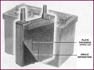
Figure 12. The 'T' type plate.
We will first deal with plate thickness,
upon which the durability of the battery depends, by showing a picture of our 'T'
type plate. This is approximately 3/32" thick and is normally
standardised for use in batteries suitable for light or medium-weight petrol vehicles.
You will notice that single separators are used. By that, we mean that adjacent
positive and negative plates are separated by a single layer of separating
material.
The 'X' Type
Plate
 For exceptionally heavy work on petrol vehicles where a longer life
is required from the battery, thicker and there-fore stronger plates are used.
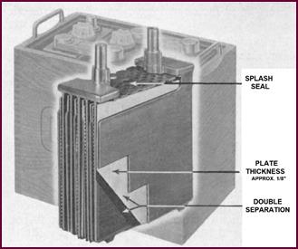
The illustration shows the 'X' type plate, which is ⅛" thick, i.e. 1/32" of an inch thicker
than the 'T' type plate shown in Figure 12.
For exceptionally heavy work on petrol vehicles where a longer life
is required from the battery, thicker and there-fore stronger plates are used.
The illustration shows the 'X' type plate, which is ⅛" thick, i.e. 1/32" of an inch thicker
than the 'T' type plate shown in Figure 12.
Figure 13. The 'X' type plate.
You will see that double separators are
used between these plates. An additional feature not yet mentioned is the 'splash
seal' or 'splash plate' – which, as the name implies, prevents splashing of the
electrolyte from the cell. This is an additional feature of these heavy duty
Lucas batteries.
The 'CX' Plate
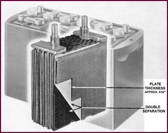 To obtain even longer life and still
greater robustness, it is necessary to use still thicker plates. The ones you
see in Figure 14 are 5/32" thick, and known as
the 'CX' plates.
To obtain even longer life and still
greater robustness, it is necessary to use still thicker plates. The ones you
see in Figure 14 are 5/32" thick, and known as
the 'CX' plates.
Figure 14. The 'CX' type plate.
The 'CF' Type
Plate
We manufacture a further type of plate, the
'CF' which is ¼" thick. This is produced specially for passenger-carrying
vehicles.
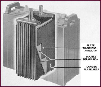 You will have gathered from the last four pictures that the idea
behind all this is simple enough: The thicker the plate, the longer the life. In
much the same way we get greater mileage from a heavy-duty tyre.
You will have gathered from the last four pictures that the idea
behind all this is simple enough: The thicker the plate, the longer the life. In
much the same way we get greater mileage from a heavy-duty tyre.
Figure 15. The 'CF' type plate.
Batteries with large numbers of the thinner
type of plates are capable of providing very heavy current discharges for short
periods, but where continuous heavy discharges are required the thicker plate batteries
are more suitable.
Comparison Of
Capacity
The second factor which governs battery
selection is capacity. The capacity of a battery is roughly pro-portional to the
area and thickness of the plates. It is the usual practice to get the largest
surface area possible, that is the maximum capacity, by using the greatest
number of thin plates per cell. This also allows easy access for the acid to
the active material of the plates.
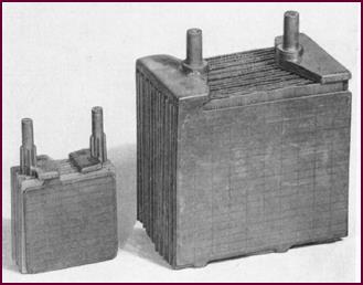
Figure 16. Battery cell comparison.
From this you can see that the capacity of
the battery is also influenced by the amount of acid in each cell. It also
follows that the capacity may often be increased by a more plentiful allowance
of acid – that is to say, by the use of wider separation and larger containers.
Thus, if some of the active material is uncovered, as when the electrolyte
level falls, the extent to which chemical action takes place is obviously
reduced and hence the capacity lessened. By this we mean that the ability of
the battery to deliver an electric current over a given period of time is
reduced.
Definition Of
Capacity
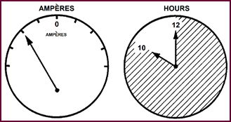 Defining this phrase: 'The ability to deliver an electric current
over a given period of time', a little more closely, we can say that here
'current' is expressed in ampéres
and 'time' in hours. This gives us then the measurement of capacity in 'Ampére-Hours', A battery can therefore be
stated to have a certain ampére-hour
capacity if it is capable of delivering a given number of ampéres over a stated number of hours.
Defining this phrase: 'The ability to deliver an electric current
over a given period of time', a little more closely, we can say that here
'current' is expressed in ampéres
and 'time' in hours. This gives us then the measurement of capacity in 'Ampére-Hours', A battery can therefore be
stated to have a certain ampére-hour
capacity if it is capable of delivering a given number of ampéres over a stated number of hours.
Figure 17. AMPÉRE – HOURS 10 amp discharge for 10 hours =
100 a/h capacity.
The 10 Hour
Rating
For the purpose of classifying batteries
according to their capacity, the time in hours must be stated. A certain amount
of agreement has been reached among battery manufacturers, this time being generally
fixed at either 10 or 20 hours. We therefore obtain the expression 'The 10 or
20 hour rating'. In England, the most generally ac-cepted principle is that the
declared ampére-hour capacity
of a car or commercial vehicle battery is: 'the total number of ampére hours obtainable in a uniform continuous
discharge lasting 10 hours, starting from a fully charged condition and
stopping at the discharged condition of 1·8 volts per cell'.
Thus the following method is normally
adopted for testing the capacity of a battery which is suspect.
The battery is first fully charged. Then it
is discharged at 1/10th of the rated capacity (10 hour rate) for 10
hours. At the end of this period the cell voltage should not have dropped below
1·8-volts.
If the voltage is below 1·8-volts in less
than the 10 hours, the battery is not giving its stated capacity.
If on the other hand the voltage remains at
this or a slightly higher figure we can be sure that the battery is up to or
above specification.
EXAMPLE 1. (CAPACITY)
A BATTERY IS STATED TO HAVE A CAPACITY OF 100
A.H. AT THE 10 HOUR RATE. AS SUCH, IT IS CAPABLE OF DELIVERING 10 AMPS. FOR 10 HRS.
(═100) BEFORE THE TERMINAL VOLTAGE
PER CELL DROPS BELOW 1·8-v.
EXAMPLE 2. (CAPACITY)
THE SAME BATTERY COULD HAVE A CAPACITY
RATING OF 114 A.H. AT THE 20 HOUR RATE. i.e. IT COULD BE DISCHARGED 5.7 AMPS.
FOR 20 HOURS BEFORE ITS TERMINAL VOLTAGE DROPPED TO 1·8- VOLTS PER CELL.
5·7
x 20 ═ 114 A.H.
Capacity
Example one (above) shows you quite simply
how the Amp./hr. capacity of a battery is determined.
This limiting of the minimum voltage to 1·8-volts
is ex-tremely important. From this you will
realise that 'capacity' is understood to express the USEFUL output of a
battery.
The second example shows just why discharge
times must be standardised and quoted when stating capacity.
Thus you will find batteries catalogued as
for example:
CX13 – 116 A/H at the
10 hour rate
and 133 A/H at
the 20 hour rate
The 10 hour
rating is however the more severe test for the battery and is the one we use in
the Lucas Organisation.
How Acid
Strength Affects Capacity
We have told you that capacity is dependent
on plate area and also on the volume of acid in each cell.
In addition, it has already been shown that
the perform-ance of a lead-acid battery depends as much on the acid-electrolyte
as on the plates themselves, bearing in mind that the electrical output can
only be maintained so long as the normal chemical reactions continue between
the acid and the active materials.
It is therefore not surprising that the
strength of the acid used for filling each cell also affects the output. The
strength of the acid not only influences the output available, but also helps
to determine what the cell voltage shall be. Within certain specific limits,
both capacity and cell voltage are affected by the strength of acid.
INFLUENCE
OF ACID STRENGTH
ON
CAPACITY
We shall deal with the normally specified
acid strengths in Part 3 of this section of the course.
The Effect Of Temperature On Battery Output.
Besides plate area and the volume and
strength of the acid, one further factor influences the capacity and hence the
output of a battery: that is, its temperature. Broadly stated: the lower the
temperature, the lower the output, the higher the temperature, the higher the
output.
There are however limits to this rule in
practice.
Let us take an actual example from discharge tests
carried out on a given battery in a fully charged condition:
|
Temperature
|
Discharge
Current
|
Volts
|
|
80 °F (26·7 °C)
|
217
amps.
|
at
10-V.
|
|
40 °F (4·44 °C)
|
178 amps.
|
at 10-V.
|
|
10 °F (–12.2 °C)
|
153
amps.
|
at 10-V.
|
The main reason
why temperature affects the output of the battery, stated simply, is that the
chemical reactions are accelerated by increasing the temperature of the
electrolyte. The acid is then more able to search into the pores of the plates,
that is, make more immediate and intimate contact with the active materials.
In cold weather the density of acid, its
viscosity if you like, increases and slows
down diffusion, thus slowing down the rate of chemical action, and hence affecting
the output.
Apart from this mainly chemical reason, at
higher temp-eratures porous separators often transmit the acid more freely than
at lower temperatures. This effectively decreases the internal resistance of
the cell, still further improving the reaction.
 Additionally, at low temperatures, the
negative plate tends to lose some of its sponginess, thus restricting the
action of the cell, limiting its output.
Additionally, at low temperatures, the
negative plate tends to lose some of its sponginess, thus restricting the
action of the cell, limiting its output.
Figure
18. Effect of temperature on battery output.
We shall now discuss further how
temperature affects our battery, particularly in relation to engine starting.
Starting
Currents
In general terms, to obtain easy starting
from cold minimum engine cranking speeds of about 90–110 r.p.m. are required.
To turn the engine over at this speed we
must have a battery capable of delivering the required current to the starter
motors down to temperatures of 20–25 °F (–6·7 – –3·9 °C).
What is more this current must be delivered
at a minimum pressure of 8·5-volts on the 12-volt system or 16-volts on the 24-volt
system.
The Tables shown for both systems give a
fair idea of the currents required for average engines of between 2 and 4
Litres which generally use the 12-volt system, and which will require from
200-300 ampéres and for engines
of 4 to 8 Litres which generally use the 24-volt system.
For the larger engines, the current would
rise very con-siderably if we did not increase the operating voltage of the
vehicle system to 24-volts.
At these voltages the current drawn from the
battery is generally limited to between 300 and 450 ampéres.
|
12-Volt
System
|
|
2 to
3 litre Engines
|
|
250 to
300 amps. at 8·5-volts
|
|
3 to
4 litre Engines
|
|
300 to
325 amps. at 8·5-volts
|
|
24-Volt
System
|
|
4 to
5 litre Engines
|
|
300
to 350 amps. at 16-volts
|
|
6 to
8 litre Engines
|
|
350
to 400 amps. at 16-volts
|
|
8 to
10 litre Engines
|
|
400
to 450 amps. at 16-volts
|
B.H.P. And
Torque
To develop full power from the starter
motor down to temperature as low as 20 °F (–6·7 °C) you will
appreciate that the battery size and capacity must be carefully chosen. Using,
for example, a 12-volt 110 A.H. battery we can obtain with a given starter
motor a turning effort or torque of 30 lb.ft. at normal temperature (approx-imately
60 °F {15·6 °C}).
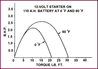 If now the same battery were used at 0 °F (–17·8 °C), the current
available would be seriously reduced and the maximum torque no more than 20 lb.
ft. That is, our battery is approximately one third less effective at the lower
temperature.
If now the same battery were used at 0 °F (–17·8 °C), the current
available would be seriously reduced and the maximum torque no more than 20 lb.
ft. That is, our battery is approximately one third less effective at the lower
temperature.
Figure 19. A 12-volt starter on 110 A.H.
battery at 0 °F (–17·8 °C) and 60 °F (15·6 °C).
Cold Weather
And The Battery
Let us consider the practical application
of all this. It is a fact that in mild summer weather we can obtain the
required cranking speed of 100 r.p.m. by using, say, an ordinary car-type
battery for a heavy commercial vehicle. But in cold weather, this battery, with
its thin plates and general light construction, would rapidly fail. Added to
the effect of low temperature on the battery, there would be increased oil
resistance, combustion difficulties and so on, until finally the work would be
outside the scope of the car-type battery. A heavier, larger capacity battery would
have to be used.
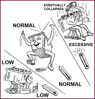
Figure 20. Battery capacity required.
In our illustration, the top battery would
be capable of cranking the engine at 60 °F (15·6 °C); but the
same battery would not be big enough for the job at the low
temperature of 20 °F (–6·7 °C). For
this application, a much larger battery would have to be used.
Conditions For
Battery Selection
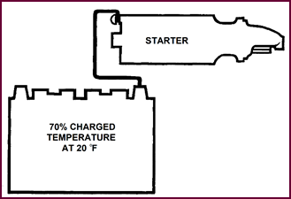 Do not forget that in cold weather, with early lighting-up time, the
battery will seldom be fully-charged in the mornings.
Do not forget that in cold weather, with early lighting-up time, the
battery will seldom be fully-charged in the mornings.
Figure 21. Battery capacity required.
It has therefore become the usual practice
for vehicle manufacturers to select a battery capable of providing the required
minimum cranking speed when in a 70% charged condition at approximately 20 °F (–6·7 °C). You will note that this temperature is considerably lower than
the freezing point of water.
Volt/Amp Curves
As a convenient and easy guide to the
selection of a battery for any specified application Volt-Ampére Curves are prepared which show
graphically the performance of a battery over any desired temperature range at
any particular state of charge.
As will be seen from the illustration the
battery voltage is plotted on the vertical ordinate and the ampéres output horizontally.
The 'Solid' line curve shows the discharge
performance of a CX 13 plate battery, 70% fully charged, and the 'Broken' line curve
the performance for a similar 7 plate battery. In both examples the discharge
readings are plotted at temperatures of 65
and 20 °F (18·3 and –6·7 °C).
Figure 22. Volt/Amp curves.
Now say for example that we require a
starting current of 275 ampéres at 8·5-volts at a temperature of 20 °F (–6·7 °C).
By following the horizontal line from 8·5-volts
to the point of intersection with the curve for the 13 plate battery, it will
be seen that well over 275 ampéres
are obtainable at the minimum temperature of 20 °F (–6·7 °C), whereas
the comparable current from the 7 plate battery would only be about 150 ampéres, as shown at the intersection with the
broken line, and whilst it might start the engine in warm weather, it would be quite
unsatisfactory under colder conditions.
The specification of Ampéres, Voltage and Temperature is generally
decided at the design stage of the engine or vehicle and governs the type and
size of battery fitted as standard equipment.
On medium and heavy goods vehicles, cold
starter currents govern the capacity of batteries used.
Cold Starting
Current
ON MEDIUM
AND
HEAVY GOODS
VEHICLES, COLD
STARTER
CURRENTS
GOVERN THE
CAPACITY OF BATTERIES USED
Now we have seen how the capacity of a
battery for a vehicle is determined by the current required for cold starting.
This applies generally to all cars and commercial vehicles. in addition the
lighting load when the vehicle is parked should be taken into consideration as
this does, of course constitute a drain on the battery, particularly if
sustained over a number of hours.
Passenger
Service Vehicles
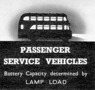 Most rules however, have their exception, and in this case the
exception is the 'public service' or 'passenger carrying' vehicle. Here the
lighting-load during normal running is very heavy, and experience has shown us
that the capacity for a battery under such service conditions can best be
calculated by multiplying the 'lighting-load' by 6. That is, for a total
lighting load of 25 amps., the minimum satisfactory capacity would be 150 Amp./hours
at the 10 hour rate. Generally this capacity would be more than sufficient to
meet the starter requirements.
Most rules however, have their exception, and in this case the
exception is the 'public service' or 'passenger carrying' vehicle. Here the
lighting-load during normal running is very heavy, and experience has shown us
that the capacity for a battery under such service conditions can best be
calculated by multiplying the 'lighting-load' by 6. That is, for a total
lighting load of 25 amps., the minimum satisfactory capacity would be 150 Amp./hours
at the 10 hour rate. Generally this capacity would be more than sufficient to
meet the starter requirements.
Figure 23. Passenger service vehicles.
Summary Of Factors Governing Battery Selection
Finally we can summarise these factors with
which we are concerned when selecting a battery for a particular vehicle.
The thickness of the plates – upon which the durability of our battery depends. And in this connection
we must not forget the separators.
The Capacity
– which determines the battery output. Remember here how the output depends on the
size and number of plates, and on the strength and volume of the acid
electrolyte.
The cold
starting current –
here, temperature, the type of starter and engine etc., must be taken into consideration.
Lamp Load –
you will remember that this applied only to Passenger Service vehicles.
All the above factors have been taken into
account by our battery technicians, and charts have been prepared which enables
us, in practice, to see at a glance which battery is suitable for a particular purpose.
We also issue publications which show the
interchange-ability of Lucas batteries with other makes, including those fitted
to American vehicles.
SUMMARY
THICKNESS
OF PLATES
TYPE
OF SEPARATION USED
CAPACITY
COLD
STARTING CURRENT
LAMP
LOAD
(PASSENGER
SERVICE VEHICLES)
We can further summarise this part by
giving you a list of battery symbols. By referring
to these symbols, a Lucas agent knows immediately the type of battery he is
dealing with. If we take for example the 'GTW9A' battery you can see
what type of container and cell connectors are used; the type and size of
plates; that it has wood separators, 9 plates per cell and a nominal voltage of
12-volts.
Symbols are used to cover the whole of
Lucas battery productions. However, we have given here only those symbols
commonly encountered.
Lucas Battery
Symbols
|
B.
|
Square ended case with completely sunken
cell connectors.
|
|
F.
|
Square ended case with provision for holding
rods.
|
|
G.
|
Square ended case with semi-linkless cell connectors.
|
|
M.
|
Monobloc container.
|
|
P.
|
Platform mounted. (motorcycle battery)
|
|
R.
|
Anchored in rubber.
(motorcycle battery)
|
|
CX.
|
Type of plate.
|
|
CF.
|
Type of plate.
|
|
T.
|
Type of plate.
|
|
X.
|
Type of plate.
|
|
U.
|
Type of plate. (for motorcycle use)
|
|
l.
|
Type of plate. (low type plate or
light-weight battery)
|
|
W.
|
Wood separators.
|
|
7, 9,
|
11, 13 etc. Number of plates per cell.
|
|
A.
|
Terminal layout, 12-volt
|
|
E.
|
Terminal layout, 6-volt
|
|
|
Example – GTW9A
|
|
Special Batteries
|
|
/F.
|
Special container.
|
|
/L.
|
Special assembly.
|
|
/T.
|
Handles moulded
integral with container.
|
|
/6,
/8.
|
Special assembly.
|
|
FR.
|
Ferguson.
|
|
Z.
|
Dry charged.
|
|
SAY.
|
Special South African.
|
|
SALY.
|
Superceded by saf. S. African.
|
|
SFLY.
|
American replacement.
|
|
SVFR.
|
American replacement.
|
|
SVWT.
|
American replacement.
|
|
SAFW.
|
American replacement.
|
|
SVWM.
|
American replacement.
|
PART THREE – PUTTING BATTERIES INTO SERVICE
We shall assume, in this part of the
course, that the batteries to be put into service have arrived in what we might
term 'factory condition'. By this, we do not mean that they have luckily
survived the rigours of transit, but that chemically they are conditioned to receive
their initial charge.
To give you an idea of the significance of
this charge, it is first essential to survey briefly the manufacturing pro-cesses
and the resultant chemical changes the battery has undergone before it reaches
you.
Plate Formation
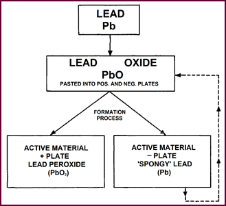 We have limited the chemistry to an absolute minimum as you can see,
giving only the essentials; and you are already familiar with some of the terms
from the first part of the course – the Active materials. Lead peroxide and 'spongy
lead' for instance. But we must start at the beginning.
We have limited the chemistry to an absolute minimum as you can see,
giving only the essentials; and you are already familiar with some of the terms
from the first part of the course – the Active materials. Lead peroxide and 'spongy
lead' for instance. But we must start at the beginning.
Figure 24. Plate formation.
Pure lead is converted into Lead oxide by
combining with the oxygen of the air. This lead oxide is the essential
ingredient of both positive and negative plates. During the 'formation process',
in which the plates are immersed in dilute sulphuric acid and an electric
current passed, the chemicals on the plates are converted into their active
form i.e., Lead Peroxide at the positive plate and 'spongy Lead' at the
negative. At this the plates are fully charged. Normal, plates are finished at
this stage, dried and ready for building batteries.
Unfortunately,
however, during the normal drying process, although the
positive plate is unaffected, the 'spongy lead' of the negative plate
inevitably combines with the oxygen of the air and reverts to Lead Oxide, thus
losing its charge.
Thus a battery fitted with these plates
leaves the factory termed 'DRY UN-CHARGED'.
Hence the necessity for the further charging process, known as 'first' or
'initial' charging.
Figure 24
shows the progressive change which takes place during formation and how after completion
the neg-ative plates return to the lead oxide form upon being exposed to the
atmosphere.
Breaking Down
The Acid
We can now set about this initial charging
with a little knowledge at our finger-tips, hoping that it won't prove a
dangerous thing.
 If you remember that, when preparing acid for filling the battery,
you dilute by adding ACID TO WATER, there will be no danger.
If you remember that, when preparing acid for filling the battery,
you dilute by adding ACID TO WATER, there will be no danger.
Figure 25. Always add acid to water
slowly.
Start with a large earthenware, glass or
lead-lined vessel; partially fill with distilled water and pour the concentrated
acid slowly into the distilled water. If, by the way, you are impulsive enough
to pour quickly, we can dissuade you by saying that hot, spitting acid is not
considered bene-ficial either to the skin or to the clothing.
Mixing
Proportions
The S.G. of the concentrated sulphuric acid
for com-mercial purposes is 1·835. The gravity of the 'filling acid' varies
between 1·350 to 1·215, and to get the correct electrolyte strength, the
proportion of acid to water should be as shown in the table above right.
|
to obtain specific gravity (when cooled to
60 °F (15.6 °C)
|
add one part by volume of acid (1·85 S.G.)
to distilled water by volume as below
|
|
1·215
|
3·9 parts
|
|
1·245
|
3·3 parts
|
|
1·260
|
3·0 parts
|
|
1·275
|
2·8 parts
|
|
1·290
|
2·6 parts
|
|
1·320
|
2·3 parts
|
|
1·350
|
1·8 parts
|
Temperature
Correction
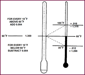 When using a hydrometer to test the electrolyte strength during or
after mixing, it must be borne in mind that all readings are to be corrected to
60 °F (15·6 °C), as, due to expansion, the gravity
varies with temperature. To correct the hydrometer reading to 'true' reading,
add 0·004 for every 10 degrees over 60 °F and subtract 0·004 for every 10 degrees under 60 °F. If, for instance, we obtained a gravity
reading of 1·300 at the mean temperature of 60 °F, no correction would be necessary. However, with a temperature of 100
°F (37·8 °C), the 'true' gravity reading would be 1·316
when the hyd-rometer indicates 1·300. Likewise at 30 °F (–1·1 °C) the 'true'
reading would be 1·288 when the hydrometer reads 1·300.
When using a hydrometer to test the electrolyte strength during or
after mixing, it must be borne in mind that all readings are to be corrected to
60 °F (15·6 °C), as, due to expansion, the gravity
varies with temperature. To correct the hydrometer reading to 'true' reading,
add 0·004 for every 10 degrees over 60 °F and subtract 0·004 for every 10 degrees under 60 °F. If, for instance, we obtained a gravity
reading of 1·300 at the mean temperature of 60 °F, no correction would be necessary. However, with a temperature of 100
°F (37·8 °C), the 'true' gravity reading would be 1·316
when the hyd-rometer indicates 1·300. Likewise at 30 °F (–1·1 °C) the 'true'
reading would be 1·288 when the hydrometer reads 1·300.
Figure 26. The effect of temperature on
hydrometer readings.
The same temperature correction must also
be obser-ved during charging, when the
battery temperature rises.
Filling The
Battery
The specific gravity of the filling-acid
varies with the type of battery, being
mainly dependent on the separator used.
In the case of WET WOOD separators for instance,
the electrolyte would be diluted by the moisture in the separators. In
batteries where our new porous rubber separators are used, the electrolyte strength
is again dif-ferent from that used in batteries with wood separators.
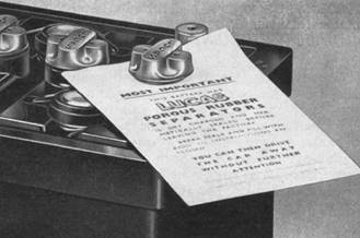
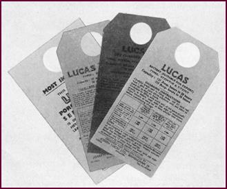 In this respect, therefore, the instructions printed on labels
attached to all Lucas batteries should be closely followed, the final
electrical output of the battery being dependent on the electrolyte strength used.
In this respect, therefore, the instructions printed on labels
attached to all Lucas batteries should be closely followed, the final
electrical output of the battery being dependent on the electrolyte strength used.
Figure 27. Different fill instruction
labels.
We will also point out that acid that is
much too strong can quite easily char the wood of the separators, apart from shortening
the life of the active materials in the plates.
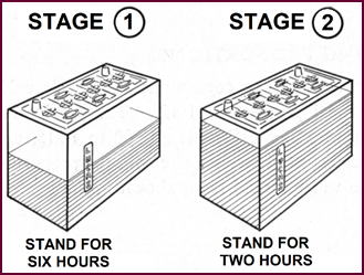 Single And Two Stage Filling
Figure 28. Two-stage filling.
Another factor too must be considered: when
batteries with wet separators are filled, a great amount of heat is generated
from the mixing of the acid and the water. Further heat too is generated as the
result of chemical action in the negative plate. This heat is likely to cause
cracks in the moulded battery container. Thus batteries with wet separators and
moulded containers must be filled in two stages. The battery should at first be
half-filled and then an interval of six hours for cooling allowed between
stages. A further two hours. should be allowed after the second stage.
This two-stage filling also applies to
DRY-UNCHARGED batteries with porous rubber separators and moulded containers.
Heat will still be generated, remember, from the negatives.
One-stage filling is however permissible
for all motor-cycle batteries.
Filling And Soaking For Wood Crated Batteries
The cells of these batteries consist of
separate ebonite jars and may be filled to the level of the separators in ONE operation.
These batteries must then be allowed to
stand for TWELVE hours before commencing the initial charge.
FILLING
AND SOAKING WOOD CRATED BATTERIES
Specific
gravity of filling acid 1·320, at 60 °F. Fill to
top of separators in ONE operation. Stand for twelve hours before commencing
charge.
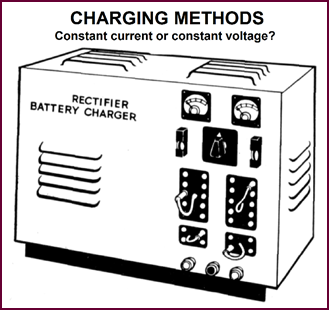 Charging Systems
Figure 29. For first charging work use
constant current charging only.
There are two charging systems in use, the
constant current and the constant voltage method.
For initial charging we strongly recommend
that only the constant current method be used. By this we mean that the
batteries are connected in series and the current flowing through them kept
constant.
If there is no alternative the 'constant
voltage' method may be used, but resistances and ammeters must be inserted in
the circuit, so that the current flowing through each battery can be
continuously supervised.
On no account should 'Rapid Chargers' or 'Boosters'
be used for initial charging.
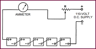
Constant
Current Charging
Note: A
maximum voltage of 110-volts has been found the most satisfactory. We must
stress here that only a DIRECT CURRENT Source can be used for battery charging.
Whenever possible, batteries of the same
capacity should be initially charged together and, for efficient work, no more
than five 12-volt batteries, or ten 6-volt batteries should be in one bank. The
number of banks depends of course on the current output available from the generator
or supply used. Variable resistances can be employed for adjusting the current flow
in each bank. The actual method of connecting the batteries in series can be
seen in Figure 30.
 Remember that a loose connection makes for an in-efficient charging
system and that any sparking is likely to fire the explosive gases released
during charging. If a battery has to be taken off charge do not forget to
switch off the charging current first.
Remember that a loose connection makes for an in-efficient charging
system and that any sparking is likely to fire the explosive gases released
during charging. If a battery has to be taken off charge do not forget to
switch off the charging current first.
Figure 30. Constant current system.
Further details of charging methods will be
dealt with in Part 4 of this section of the course, 'Batteries In Service'.
Duration And
Rate Of Initial Charge
Our label instructions giving the duration
and rate of the initial charge MUST be followed if the best performance and the
longest life are to be obtained from the battery.
DURATION
AND RATE OF CHARGE
Flat
Plate Batteries:
up
to 80 hours.
Armoured
Plate Batteries:
100
hours actual.
Maximum
allowable temperature when on charge:
Temperate
climates 100 °F.
Hot
climates 110 °F.
In general the initial charging rate of
approximately 1/15 of the nominal capacity at the 10 hour rating. Charge at
this constant current for 80 hours, or until voltage read-ings and temperature –
corrected S.G. readings show no increase over five successive hourly readings.
Throughout the charge, the acid must be kept
level with the top of the separators in each cell by the addition of acid
solution of the same gravity as the original filling-in acid. If for any reason
the charge has to be continued beyond the point where S.G. and voltage readings
remain constant for five consecutive hours, distilled water should be used for topping
up.
As far as possible, the initial charge
should not be interrupted, but if the temperature of the electrolyte in any
cell reaches 100 °F (37·8 °C), the charging should be stopped and the
temperature allowed to fall at least 10 °F (0·56 °C) before
charging is resumed.
Adjustment Of
Acid Strength
At the end of the charge, i.e. when S.G.
and Voltage measurements remain substantially constant, carefully check the
S.G. in each cell to ensure that it lies within the limits specified by the
manufacturers' instructions. If any cell requires adjustment, some electrolyte
must be syphoned off and replaced with a corresponding quantity of either acid
of the strength used for the original filling or distilled water, according to
whether the S.G. is too low or too high. After such adjustment, the gassing
charge should be continued for one to two hours to ensure adequate mixing of
the electrolyte.
The Dry-Charged
Battery
Obviously a great amount of time and
trouble would be saved if this business of initial charging were not neces-sary.
With this thought in mind, our battery technicians set about producing a
battery which could be put directly into service without initial charging.
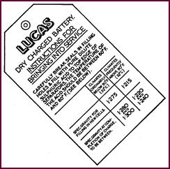
 The result of their labours is the Lucas 'DRY CHARGED' battery –
recognisable by the RED instruction label.
The result of their labours is the Lucas 'DRY CHARGED' battery –
recognisable by the RED instruction label.
Figure 31. The dry-charged battery
label.
In the absence of the label, the
Dry-Charged Batteries can always be distinguished by the letter 'Z' appearing
in the type symbol. For example the lettering GTZ7A will appear on one of the
cell connectors - The 'Former'.
No Initial
Charging
 You will remember that before dealing with initial charg-ing, we
explained why this was necessary. During the normal drying process after the
formation charge, the negative plate loses its charge, the 'spongy lead' active
material combining with the oxygen of the air. A method of drying the plates in
an oxygen-free atmosphere has been perfected, the result being that both
positive and negative plates remain charged. The sets of plates are then
assembled, the separators inserted and the cells hermetically sealed. Thus we have
a battery which can truly be termed 'DRY-CHARGED'. This battery can be put into
service immediately without initial charging.
You will remember that before dealing with initial charg-ing, we
explained why this was necessary. During the normal drying process after the
formation charge, the negative plate loses its charge, the 'spongy lead' active
material combining with the oxygen of the air. A method of drying the plates in
an oxygen-free atmosphere has been perfected, the result being that both
positive and negative plates remain charged. The sets of plates are then
assembled, the separators inserted and the cells hermetically sealed. Thus we have
a battery which can truly be termed 'DRY-CHARGED'. This battery can be put into
service immediately without initial charging.
 Putting The Dry
Charged Battery Into Service
Putting The Dry
Charged Battery Into Service
Figure
32. Lucas dry-charged battery label.
After breaking the seals each cell should
be filled with electrolyte of the correct S.G. The battery MUST be filled to
the top of the separators in one operation. After this 'one-stage' filling,
the battery will be up to 90% charged, and may immediately be fitted to a
vehicle. When time permits however, a short 'freshening charge' will ensure
that the battery is completely charged. Such a freshening charge should last no
more than 4 hours at the normal recharge rate of the battery. During this
charge, the electrolyte must be maintained at the level of the sep-arators by
the addition of distilled water.
Our instructions should again be referred
to for elect-rolyte strengths and recharge rates. We emphasise here that the 'dry-charged'
battery can be treated in service in exactly the same manner as normal
batteries.
PART FOUR – BATTERIES IN SERVICE
Batteries In
Service
This section of the Battery Course deals
mainly with practical points concerning the maintenance of batteries in
service, remembering that without proper attention, even the best product is
doomed to early failure.
Battery Stowage
Let us first make a check on the
installation of the battery. By this we mean the battery stowage and all metal
parts in the immediate proximity of the battery, including the lugs and the
earth cable or braid.
Figure 33. A typical battery
installation in a vehicle.
The battery should be kept clean and dry
and any traces of acid spillage removed by ammonia, or hot water if this is not
available. Otherwise corrosion and extensive dam-age to the metal work will
result.
Battery Lug
(Old Clamp Type)
Battery lug corrosion is a more serious
matter than is generally realised. Heavy corrosion on the battery lugs and
posts results in considerable voltage drop when a heavy current is passing, for
example, when the starter is operated voltage drop will usually be noticeable
by sluggish operation of the starter motor.
 The rate of corrosion is dependent on two factors: The thickness of
the lead covering the cast brass of the lug and the amount of acid allowed to
accumulate on the battery top.
The rate of corrosion is dependent on two factors: The thickness of
the lead covering the cast brass of the lug and the amount of acid allowed to
accumulate on the battery top.
Figure 34. Corrosion at a clamp-type
battery lug.
This latter is your responsibility: we, on
our part, as manufacturers, produce a special alloy which is far in advance of
the normal lead-coated brass lug, and reduces corrosion to an absolute minimum.
This alloy lug is now used mainly for commercial vehicles, with a new diecast
lead lug superseding the old clamp type on normal cars.
Battery Lug (Die
Cast)
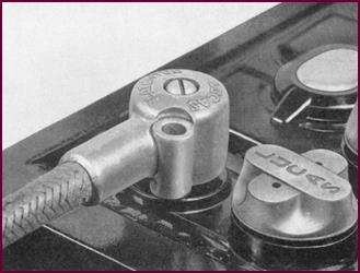 Here we give an illustration of the die-cast battery lug fitted
almost exclusively on present-day British cars. This lug further reduces
corrosion.
Here we give an illustration of the die-cast battery lug fitted
almost exclusively on present-day British cars. This lug further reduces
corrosion.
Figure 35. The Lucas die-cast battery
lug.
The following points should be observed
when refitting these lugs.
Clean off any oxidation from the battery
post and smear the post and lug with commercial Vaseline. Grease must
not be used for this purpose.
When fitting the lug, make sure that the
two surfaces marry together properly. Insert the 'Parker-Kalon' locking screw
after pressing home the lug on to the tapered battery post.
If these precautions are observed, no bad
connections can develop and removal of the lug is always easy.
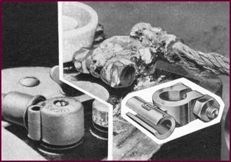
Replacement Kit
 A standard Lucas replacement kit is available for repairing either a
corroded brass lug, or a damaged length of battery cable. As you can see in
this photo-graph, the new die-cast lug is used. This, coupled with a length of
starter cable, a brass connector- sleeve, a self-tapping screw, and, in the
case of the insulated cable, a piece of rubber sleeving, constitutes the kit.
A standard Lucas replacement kit is available for repairing either a
corroded brass lug, or a damaged length of battery cable. As you can see in
this photo-graph, the new die-cast lug is used. This, coupled with a length of
starter cable, a brass connector- sleeve, a self-tapping screw, and, in the
case of the insulated cable, a piece of rubber sleeving, constitutes the kit.
Figure 36. Battery lug repair kit.
In the top picture the old battery lug has
been cut off; half an inch of the existing
cable outer-covering stripped back; the rubber sleeve pulled over the
new section of cable; the bare end of the existing cable pushed into the brass
connector-sleeve, and the joint soldered.
Insulating The
Joint
After allowing the joint to cool, it should
be bound with a few turns of insulation tape and the rubber sleeving pulled
over.
After smearing the battery post with
commercial Vaseline, the lug can be pushed firmly into position and the
self-tapping screw inserted.
The replacement kit for the non-insulated
battery lead, the positive earth cable on the modern car, consists of a braided
earth cable with a die-cast lug, a brass connector and a self-tapping screw.
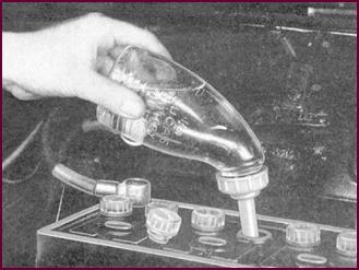
Hydrometer
Testing
 We shall now concentrate more on the inside of the battery, dealing
first with acid and voltage testing, and then with the electrolyte level.
We shall now concentrate more on the inside of the battery, dealing
first with acid and voltage testing, and then with the electrolyte level.
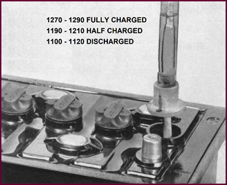
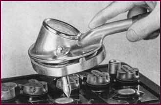
Figure 37. Specific gravity test with a
hydrometer.
We have already explained the meaning of specific
gravity in Part 1 of this section of the course and will now merely quote
approximate gravity readings for our batteries:
Fully Charged 1270-1290
Half Charged 1190-1210
Discharged 1100-1120
 The Heavy Discharge Test
Figure 38. Making a heavy-discharge test
on a battery.
The hydrometer test gives us a fairly
accurate account of the state of charge of each cell, but a further test must
be made to make sure that each cell will supply heavy cur-rents at the required
voltage, the heavy starting currents for instance. For this purpose, we use a 'heavy
discharge tester' which puts an electrical load on each cell. The load, or resistance,
takes at least 150 ampéres from
the cell in the case of a car battery, thus reproducing condi-tions similar to
those existing when the starter motor is operated. If the hydrometer test
showed the cell to be charged, and if, under these test conditions, the cell
voltage remains constant at approximately 1·5 to 1·6-volts, we can be sure the
cell is serviceable. A rapidly falling voltage reading indicates a weak cell. The
drop tests should be held in position for about 15 seconds for each cell in the
battery.
We use the same type of tester for
motorcycle batteries, but a smaller load, this time 12 ampéres is adequate.
For a commercial vehicle batteries a drop
tester with a load of 300 ampéres
must be used.
The Importance Of Charging From An External Source
If the heavy discharge test proves the
battery to be serviceable, but the gravity reading indicates that it is only
half charged, i.e. between 1190-1210, the battery must be re-charged from an
external source. It should not be put back into normal service until it is at
least 80% charged. Care must be taken that this minimum figure is reached, particularly in winter-time when heavier
currents are needed for starting.
DISCHARGED
BATTERIES
BATTERIES
BELOW HALF CHARGE IN SERVICE SHOULD BE RECHARGED BY AN EXTERNAL SUPPLY 80% FULL
CHARGE MINIMUM.
Recharging In
Service
 Generally, recharging presents no
problems if the charging rates quoted on our instruction labels are adhered to.
Generally, recharging presents no
problems if the charging rates quoted on our instruction labels are adhered to.
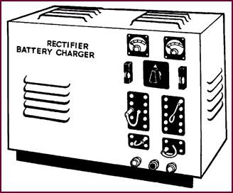
Figure 39. A typical battery charger.
The normal charging rate is usually
approximately 1/10 of the Amp./Hour capacity of the battery at the 10 hour
rate. The charge must be continued until voltage and specific gravity readings
show no increase over three successive hourly readings.
Charging
Methods
Either the constant current method, which
we advocated for initial charging, or the constant voltage method may be
employed for recharging. In either case a DIRECT CURRENT supply must be used. The
connections to be made differ with the method and can be seen from the Figure
40. You will see that, using the constant current method, the batteries are
in series. Thus a limit is set to the number of batteries that may be charged
in series, since the voltage of the batteries when fully charged must not
exceed the supply voltage. It is found in practice that the most suitable arrangement is ten 6-volt batteries or five 12-volt
batteries when charging from a 110-volt supply.
Figure 40. Method of connecting
batteries for charging.
With the constant voltage system, the
batteries are con-nected in parallel, usually to a low voltage motor-gener-ator
set. The number of batteries that can be charged on one generator is here
limited by the rated current output of the generator, and the total of the charging
currents required for all the batteries must not exceed this output.
The supply voltage can again be regulated
by a rheostat, and, if necessary, a rheostat or resistance can be in-cluded in
the supply line to an individual battery, where a lower charging rate is
required for this battery.
Boost Charging
Rapid chargers or 'boosters' should only be
used for charging if there is any real urgency. They must always be supervised
and should never normally be used to replace the standard charging method. No harm will be done through rapid charging if the
battery is in a healthy discharged condition, although obviously rather more
intel-ligent supervision will be needed than for ordinary charging.
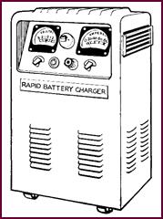
Figure
41. A typical rapid battery charger.
A battery can be substantially recharged,
i.e., to bet-ween 70%–80% of its fully-charged state, in anything between 30–60
minutes, dependent upon the state of discharge and the battery temperature.
And temperature is here the controlling
factor. On no account should a temperature of 110 °F (43·3 °C) be exceeded,
or the battery will be ruined.
Judge for yourselves: at 140 °F (60 °C) the paste starts leaving the grids.
Thermostat For Temperature Control During Boost
Charging
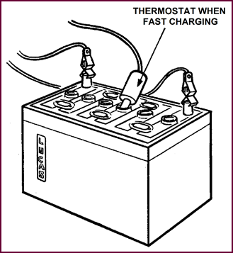 For the purpose of controlling temperature, a thermostat switch must
be employed. This should be placed in the middle cell of 6-volt batteries, and
either of the two centre cells of 12-volt batteries.
For the purpose of controlling temperature, a thermostat switch must
be employed. This should be placed in the middle cell of 6-volt batteries, and
either of the two centre cells of 12-volt batteries.
Figure 42.
Temperature to be kept below 110 °F (43·3 °C).
While we are discussing this subject of
temperature, we will remind you once more of the necessity for temp-erature correction of gravity readings if variations
from the mean temperature of 60 °F (15·6 °C) are encountered.
The importance of correct charging cannot
be over-estimated as far as the life of the battery is concerned. If, at any
time, particularly in winter, a battery should become completely discharged, it
is very bad practice to leave it in the hope that it will become fully
recharged by the vehicle dynamo. Unless the battery is charged by an external
source, it will probably never become more than half-charged, and, even though
it appears to be working satisfactorily, the plates harden and the life of the
battery will be considerably shortened.
Effect Of Temperature On
Discharged Batteries
When left in a low state of charge ,
batteries can freeze easily. You can see from the figures given that a battery
with a gravity of 1100 will freeze at 18 °F (–7·8 °C), that is
14° (–10 °C) of frost, a condition by no means im-possible
even in the mild climate of the British Isles.
Freezing
Point Of Water
(i.e. 1·000) – +32
°F (0 °C).
Freezing
Point Of Electrolyte At
1·100 – +18 °F (–7·8 °C).
Freezing
Point Of Electrolyte At
1·200 – –17 °F (–27·2 °C).
Freezing
Point Of Electrolyte At
1·300 – –95 °F (–70.6 °C).
The Electrolyte
Level
 We must deal with one further point as far as main-tenance of
batteries in service is concerned, that is, topping up.
We must deal with one further point as far as main-tenance of
batteries in service is concerned, that is, topping up.
Figure 43. Showing the correct
electrolyte level.
We have already touched on this subject at
various times in this section of the course and will now give a short summary.
The electrolyte level should be maintained at the top of the separators by
topping-up with distilled water. Underfilling will harm the battery plates;
overfilling can only result in acid spillage, probably all over the engine
compartment. Topping-up to the correct level leaves ample room for the charging
gases to expand without flooding the Vent Plugs and causing external
lug-corrosion and damage to sur-rounding metal work and upholstery.
During the normal service life of the
battery it should never be necessary to top up with acid electrolyte.
Of course if an appreciable amount of acid has been spilled from the battery, it may be replaced by acid of
the same S.G.
We also strongly disagree with the practice
of changing the battery acid. It should never normally be necessary and, when
the battery is turned upside down, sediment from the bottom of the container falls
between the plates, becomes wedged and inevitably causes short circuit.
Battery Filler
 This business of 'topping-up' is often neglected simply because in
some cases it requires a contortionist to see into the top of the battery
tucked away somewhere at the back of the engine compartment.
This business of 'topping-up' is often neglected simply because in
some cases it requires a contortionist to see into the top of the battery
tucked away somewhere at the back of the engine compartment.
Figure 44. Lucas Battery filler in use.
Lucas have simplified the process by
patenting this battery filler. The device ensures that filling automatic-ally ceases
at the separator level.
Current Losses
Having set-out to discuss the maintenance
of batteries in service, we must mention current losses which occur when the
battery is standing.
Any charged battery that is left standing
will discharge itself over a period of time. This self-discharge is inevit-able,
taking place even under the best conditions. The diagram (Figure 45)
shows exactly at what rate this takes place. You can see quite clearly how higher
temperature increases the rate.
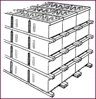
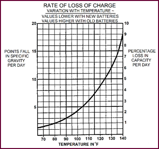 Figure 45. Rate of loss of charge.
You will realise now why it is so important
to keep the surface of the battery clean and dry and thus minimise
self-discharge.
Current leakage can also occur internally
between two adjacent cells, when for some reason the cell partition is
defective or the sealing compound cracked.
PART FIVE – BATTERIES IN STORAGE AND SERVICE
Storage Conditions Temperature
And Stacking
We shall now attempt to deal with a very
large Subject very briefly, in that we shall give you a clear idea of the
conditions necessary for battery storage, without going into details of actual
storage rooms, etc.
We shall deal separately with dry
batteries, (that is with batteries that have not been filled and charged): with
charged batteries and with the latest dry-charged batteries.
All batteries, whatever their breed, should
be stored in as dry an atmosphere as possible, within temperature limits of 32
°F and 90 °F (0 °C and 32·2 °C). They should be kept out of the direct rays of
the sun.
Dry batteries can be stacked, provided that
they are placed the correct way up and not on their sides. Car types and X and
CX commercial type batteries should be stacked not more than four high, wooden spacers
being placed lengthwise between layers. If the batteries are cartoned, they may be stacked six high. CV and CF
types, the heavier batteries, should not be stacked more than one
battery high, either in storage or transit.
If the above conditions are observed, dry
batteries need no further supervision and, providing the cell seals are not
damaged, may be stored more or less indefinitely. However, generally speaking
the sooner a new battery is charged the better; prolonged storage usually neces-sitates
longer first charging.
Figure 46. Temperature 32 °F (0 °C) to 90 °F
(32·2 °C).
Storing New
'Charged' Batteries
To retain new 'charged' batteries in first
class condition each battery should receive a 'freshening charge' of four hours
every month at the recommended recharge rate. Care should be taken to see that
the cells are topped-up with distilled water to the level of the separators.
And we repeat that the surface of the batteries must be kept clean and dry. This
precaution minimises self-discharge, the reason for the 'freshening-charge', of
course, you remember from the graph shown above in Figure 45 how the self-discharge
increased with temperature. This is the reason why the temperature of the
storage room must be controlled. Too-high a temperature, will mean that the
freshening charge must be-given more frequently than once a month.
Storing 'King Of The Road' And Dry Charged Batteries
Our latest batteries, both the normal dry
uncharged and the 'dry-charged' types lend
themselves ideally to storage, due to their being fitted with porous rubber separators.
In fact, in the case of the dry uncharged
battery, our engineers have proved that with these new separators, the usual
hermetic sealing ('flash seal') is no longer necessary.
It will be appreciated however from what we
have said earlier concerning the method of production of the 'dry-charged'
battery, that the sealing must still be retained. The vent plugs are provided
with small plastic stoppers and then taped over.
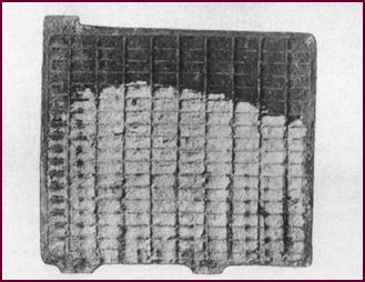 Figure 47. Illustrating Lucas King Of The Road battery features.
In-Service
Battery Problems
The illustrations which follow will show
you just what is likely to happen to the inside and outside of a battery if it
is not properly looked after.
 If these batteries had been properly maintained, that is: kept clean
and dry, topped-up, and correctly charged, these faults would not have
occurred.
If these batteries had been properly maintained, that is: kept clean
and dry, topped-up, and correctly charged, these faults would not have
occurred.
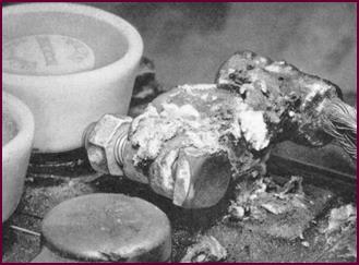
Corroded Battery
Lugs
 The result of neglect. Keeping the battery top dry, and the lugs
clean and coated with Vaseline would have avoided this. Even our new die-cast lug,
although limiting corrosion to an absolute minimum, must still be efficiently
maintained.
The result of neglect. Keeping the battery top dry, and the lugs
clean and coated with Vaseline would have avoided this. Even our new die-cast lug,
although limiting corrosion to an absolute minimum, must still be efficiently
maintained.
Figure 48. Corroded battery lug.
Acid Level
Neglect
This cell had not been topped up. You can
see that the acid level was only halfway up the plates instead of at the top of
the separators. The plates are divided into upper and lower areas of different colour
and texture. It is clear too that the battery had been standing idle in a badly
discharged condition. In this photograph of the positive plate, the white of the
inert Lead Sulphate is very obvious against the chocolate-coloured active lead
peroxide at the top.
Figure 49. Effect of acid level neglect.
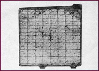
Over-Discharged
Negative Plate
Here we have over-discharging as it affects
the negative. The paste on this negative plate is hard and light in colour –
Lead Sulphate again.
Figure 50. An over-discharged negative
plate.
This can be the result of either over-discharging,
persistent undercharging, or long standing without charging.
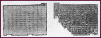
Over-Charged
Negative And Positive Plates
The result of over-charging. These negative
and positive plates were taken from the same cell. The negative material was
spongy and soft and you can see how, in the right hand illustration, the
positive material is leaving the grid. See Figure 51 on Page 24.
 This lifting of the active material pellets on the positive plate
could equally well have been caused by freezing when the battery was in a low
state of charge.
This lifting of the active material pellets on the positive plate
could equally well have been caused by freezing when the battery was in a low
state of charge.
Over-Charged
Negative Plate
This negative plate shows even more clearly
the
result of overcharging. You can see that
the active
material surface is covered with small
blisters.
See Figure 52 on Page 24.
 Figure 51. Over-charged negative and positive plates.
Figure 52. Example of an over-charged
negative plate.
Much
Over-Charged Negative Plate
Carrying this over-charging of the battery
a little further, the negative plate would have this appearance. The grid, as
you can see is weak and broken and the paste conspicuous in many places by its
absence.
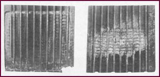
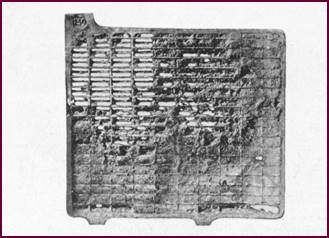
Figure 53. A much over-charged negative
plate.
Buckling Due To
Over-Charging
Heavy over-charging
can also cause buckling of the plates. These negative
and positive plates come from the same cell. The over-charging had forced the active
material from the Positive plate, on the right of the illustration, and the
sediment caused an internal short circuit which led to increased buckling of
the positive plate and disintegration of the negative.
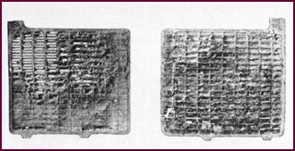 Figure 54. Examples of buckled plates, not easy to see.
We hope this buckling is evident from the photograph.
If you look closely at the two inside edges of the plates you will notice that
the positive is bent away from the straight edge of the negative.
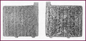
Buckling Due To
Over-Discharging
 Buckling of battery plates can also be caused by a heavy
over-discharge. The negative plate on the left is hard, and as you would
expect, badly sulphated. The positive grid has been broken up by the buckling or
expansion.
Buckling of battery plates can also be caused by a heavy
over-discharge. The negative plate on the left is hard, and as you would
expect, badly sulphated. The positive grid has been broken up by the buckling or
expansion.
Figure 55. Severe buckling due to
over-discharging.
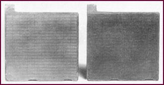
Buckling, The
Effect On Separators
 These wood separators were taken from a cell having buckled plates
due to over-discharge. Note the impres-sion of the plates, made when they were expanded
and particularly the wear at the bottom and centre.
These wood separators were taken from a cell having buckled plates
due to over-discharge. Note the impres-sion of the plates, made when they were expanded
and particularly the wear at the bottom and centre.
Figure 56. The effect of buckling on
separators.
Healthy Plates
 When in a healthy condition and normally charged, the negative plate
should be slate grey in colour with a soft surface – soft enough to mark easily
with the finger nail, but in no way 'soggy' or blistered.
When in a healthy condition and normally charged, the negative plate
should be slate grey in colour with a soft surface – soft enough to mark easily
with the finger nail, but in no way 'soggy' or blistered.
Figure 57. A pair of healthy plates.
The positive plate should be chocolate
brown with a relatively hard surface.
In both cases the grids should show no
signs of wear, nor should the paste pellets be lifting.
Postscript
Perhaps, after studying all this
information on the various phases of battery construction, repair and service,
the student may have gained the impression that this is a highly complex
subject. It certainly is, when considered from the manufacturing point of view,
but we have given you an insight into some of the deeper technical prob-lems
merely in the hope that you will appreciate how important it is that a battery is
correctly selected for its work and intelligently serviced throughout its life.
One essential fact stands out in connection
with a battery that does not apply to any other electrical component, and that
is – that being an electro-chemical unit – it commences its effective life from
the day of its assembly, and whether it is put into active use on a vehicle or
kept on a shelf in the stores, its life has started and regular maintenance in
one form or another is of the utmost importance.
If the advice and instructions given in
this book are understood and closely followed, we are confident that your
efforts will be amply repaid in the form of satisfied customers.