OWNER’S INSTRUCTION BOOK
For the operation and maintenance
of the 1½-litre 4-cylinder
JAVELIN JUPITER
Issued September 1950
A copy of this book is issued with every car.
Extra copies may be obtained from Main Agents, three shillings each, net.
JOWETT CARS LIMITED
IDLE, BRADFORD, YORKSHIRE, ENGLAND
and 48 ALBEMARLE STREET, LONDON, WC1
Telephone Telegrams Cables
341 Idle, Bradford Jowcars, Bradford Jowcars, Bradford
In the interests of quick service, will you please observe the following:
Written communications should be addressed to
JOWETT CARS LTD., IDLE, BRADFORD
If telephoning please ring: Queensbury 2381
Telegrams and Cables: JOWLIM, BRADFORD
FOREWORD
 ln preparing this
instruction book, it has been our aim to present in a simple and concise
manner, the information necessary for the operation, care and general
maintenance of the 1½-litre JAVELIN-JUPITER car. This vehicle will give you many
years of enjoyable motoring if it is driven with reasonable care, and is
properly and regularly lubricated and serviced. Hints and instructions to this
end will be found in the ensuing pages.
ln preparing this
instruction book, it has been our aim to present in a simple and concise
manner, the information necessary for the operation, care and general
maintenance of the 1½-litre JAVELIN-JUPITER car. This vehicle will give you many
years of enjoyable motoring if it is driven with reasonable care, and is
properly and regularly lubricated and serviced. Hints and instructions to this
end will be found in the ensuing pages.
The owner is recommended to become thoroughly acquainted with the construction and mechanical details of the car, and by reading this book to know where all points requiring lubrication are located. Only in this way can the servicing of them, at the regular recom-mended mileages, be attended to rapidly and efficiently, in the manner of a well-rehearsed drill.
It will be noted that reference to body interior, etc., in this book refer only to the factory-built bodywork. In cases where special bodywork has been fitted, the owner is advised to discuss the appropriate points with his supplier, so that he is fully acquainted with these details when taking delivery of the car.
For the more detailed repair and overhaul operations, owners are strongly recommended to take their cars to the nearest Jowett Main Agents.
Registration And Servicing Data
|
Engine Dimensions |
Bore |
2.85” (72.5 mm) |
|
|
Stroke |
3.54” (90 mm) |
|
|
Number of Cylinders |
4 |
|
|
Piston Displacement |
90.9 cu. in. (1,486 cc) |
|
|
RAC and SAE Rating |
13.05 |
|
|
Firing Order |
1, 4, 2, 3 |
|
|
Brake Horsepower |
60 at 4,500 rpm |
|
|
Compression Ratio |
8.0:1 |
|
Alternative Compression Ratio for Low-Grade Fuel 7.6:1 |
||
|
Car Dimensions |
Overall Length |
168 in. (4.140 metres) |
|
And Weights |
Overall Width |
62 in. (1.570 metres) |
|
|
Overall Height U/L |
56 in. (1.422 metres) |
|
|
Wheelbase |
93 in. (2.362 metres) |
|
|
Track – Front |
51 in. (1.295 metres) |
|
|
Track – Rear |
49 in. (1.244 metres) |
|
|
Ground Clearance |
8 in. (20.32 cm) |
|
|
Dry Weight |
16 cwt. (812 Kgs) |
|
Capacities |
Fuel Tank |
10 gals. (45.336 litres) |
|
|
Cooling System |
2 gals. (9.092 litres) |
|
|
Engine Sump |
10 pints (5.7 litres) |
|
|
Gearbox |
1½ pints (0.85 litre) |
|
|
Rear Axle |
2 pints (1.13 litres) |
|
Tyre Size & Pressures |
5.50 x 16 |
26 psi Front and Rear |
|
Sparking Plugs |
Champion |
L10-S |
|
Carburettors |
Zenith |
30 V.I.G.5 |
|
Distributor |
Contact Breaker Point Gap Set 0.010 to 0.012 in. |
|
|
|
Ignition Timing Set at T.D.C. to ⅜ in. A.T.D.C. on Flywheel Diameter. |
|
|
Valve Tappets |
Hydraulic automatically adjusting type, requiring no adjustment after initial setting. Valve clearance with tappets ‘deflated’ set at 0.060 – 0.085 in. (1.5 to 2.2 mm). |
|
|
Lamp Bulbs |
Headlamps R.H.D. |
Lucas 12/48 Pre-Focus Number 302 |
|
|
Headlamps L.H.D. |
Lucas 12/48 Pre-Focus Number 303 |
|
|
Side Lamp |
Lucas 12-volt 6-W Miniature Bayonet Cap |
|
|
Tail and Stop Lamp |
Lucas 24/6 W., D.C. Indexed Bayonet Cap. |
|
|
Instrument Panel |
12-V., 2.4-W. Screw Cap 11 mm Envelope. |
|
|
Ignition Warning Lamp |
12-V., 2.4-W. Screw Cap 11 mm Envelope. |
|
|
Direction Indicators |
Lucas No. 256. 12-V. 3-W. Festoon Type. |
|
|
Screen Wiper Warning Lamp |
12-V., 2.4-W. Screw Cap 11 mm Envelope. |
|
|
Number Plate Lamp |
Lucas 12-volt 6-W Miniature Bayonet Cap |
|
|
Headlamp Main Beam Warning Lamp |
12-V., 2.4-W. Screw Cap 11 mm Envelope. |
|
Battery |
2 – 6-Volt 50 Amp. Hour, Lucas Type |
|
|
Gear Ratios |
Top Gear |
4.56 to 1 |
|
|
3rd Gear |
6.25 to 1 |
|
|
2nd Gear |
9.90 to 1 |
|
|
1st and Reverse Gear |
16.25 to 1 |
|
Front Wheel Alignment |
Parallel to ⅛” toe-out (measured on line of hubs at wheel rim diameter). |
|
|
Engine Number |
Stamped on L.H. front of engine. |
|
|
Chassis Number |
Stamped on both top corners of front chassis cross tube. May also be beside radiator mountings. |
|
|
Body Number |
Stamped on plate, engine side of dash panel. |
|
CONTROLS AND INSTRUMENTS
![]() All body details quoted in the following section on
controls and instruments refer only to the factory-built body. The owner who is
taking delivery of a car with a body built to his individual requirements is advised
to obtain the information he needs from the Main Agent supplying the car, as
this will not necessarily be identical with the details given below.
All body details quoted in the following section on
controls and instruments refer only to the factory-built body. The owner who is
taking delivery of a car with a body built to his individual requirements is advised
to obtain the information he needs from the Main Agent supplying the car, as
this will not necessarily be identical with the details given below.
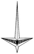
A view of the driving compartment of the car is shown in Figure 1 (Page 9), which illustrates all the main controls. These may be classed as driving controls, electric and lighting controls, and instruments. A new owner should make himself thoroughly familiar with these so that he is able to operate them automatically even in the dark.
Driving Controls
Accelerator. The pedal is connected through a short Bowden Cable to the interconnected throttle controls. Do not depress the pedal when starting the engine from cold.
Brake Pedal. Operates on all four wheels through an hydraulic system to the front, and mechanical linkage to the rear wheels.
Clutch Pedal. Depress the pedal to disengage the drive from the engine to the gearbox. Do not rest your foot on the clutch pedal when driving, as this will cause rapid wear to the clutch and thrust race.
Gear Lever. The position of the gear lever for the four forward speeds and reverse is shown in Figure 1. Before attempting to engage the reverse position the press button at the end of the gear lever must be depressed.
Handbrake. The handbrake lever operates on the rear wheels, through the mechanical linkage.
Electrical And Lighting Controls
These are situated on the centre part of the Instrument Panel.
The Ignition Switch is operated by the key, also used for locking the car door, and is in the centre of the lighting switch.
The Lighting Switch when turned clockwise progressively takes up two positions. In the first, the side and tail lamps and number plate lights are on. In the second, the headlights, side, tail, and number plate lights are on.
The Starter Switch operates the engine starter only after the ignition is switched on.
The Panel Light Switch, Windscreen Wiper Switch and Heater Switch are of the ‘pull-out’ type. When pulled out the respective components named are switched on, and when pushed in again the components are switched off. The panel lights cannot be illuminated unless either the side or headlamps are switched on.
An additional switch marked ‘F’ is also fitted for operating a Fog Light if required.
The Trafficator Switch raises the left or right hand direction indicator arms when moved to the left or right respectively; it reverts to the central position auto-matically after a lapse of about a quarter of a minute.
The Carburettor Choke Control (marked CHOKE) should be pulled out when starting the engine from cold (see Page 11). The control will hold in any desired position if turned slightly left or right.
The Horn Button is in the centre of the steering wheel.
The Dipper Switch, when depressed, dips the beams of both headlamps.
This arrangement can be varied if so desired, by disconnecting the ‘dipped position’ lead to either of the lamps, so that the lamp is extinguished in the dipped position.
Instruments
The Speedometer and Time Clock, Tachometer and Head Lamp Warning Light, Petrol Gauge, Oil Pressure and Temperature Gauge, Water Thermometer and Ammeter are grouped on the Main Panel in front of the driver.
The Speedometer is provided with a ‘trip’ figure, which can be returned to zero by pressing and turning the control which will be found immediately below the instrument.
The Tachometer, which indicates the engine speed in revs. per min., is driven through a 3 to 1 reduction ratio from the rear of the dynamo shaft. The engine should not normally be run at speed exceeding 5,500 R.P.M. This figure is indicated on the Tachometer by a broad red line.
The Oil Pressure Gauge should normally show a reading of 55-60 lbs. per sq. inch at 2,000 R.P.M.
The Oil Temperature Gauge, which is incorporated with the Pressure Gauge, should not indicate a temperature exceeding 100 °C., even under the most arduous conditions.
The Water Temperature Gauge shows the temperature of the Radiator Header Tank, which is thermostatically controlled. The gauge should read about 75 °C. under average conditions.
The Ammeter indicates the charge going into or being taken from the battery. The dynamo output is automatically adjusted to the state of the battery by the regulator in the control box on the engine side of the dash.
The Electric Clock, fitted below the speedometer, can be reset in a similar manner to the speedometer trip reset.
The Ignition Warning Light (Red), which is fitted above and to the left of the lighting switch, glows when the ignition switch is ‘on’ and is extinguished when the dynamo commences to charge.
The Wiper Warning Light. This is on the right of the headlamp switch and shows a blue light when the wiper motor is in operation. Under no circumstances must the wiper motor be left switched on if the wiper arms fail to operate. In a case of this nature the Main Agent or Service Station should be contacted.
 The Headlamp Warning Light is the small red
light in the lower face of the tacho-meter which is illuminated when the
headlamps are being used in the main beam position.
The Headlamp Warning Light is the small red
light in the lower face of the tacho-meter which is illuminated when the
headlamps are being used in the main beam position.
Figure 1. Driving Controls
|
A |
Cigar Lighter |
N |
Tachometer |
|
B |
Heater Switch |
O |
Headlamp Warning Light |
|
C |
Fog Lamp Switch |
P |
Speedometer |
|
D |
Ignition Warning Light |
Q |
Time Clock |
|
E |
Ignition Switch |
R |
Water Temperature Gauge |
|
F |
Direction Indicator Switch |
S |
Oil Pressure and Temp. Gauge |
|
G |
Lighting Switch |
T |
Horn Button |
|
H |
Wiper Warning Light |
U |
Choke Control |
|
I |
Wiper Switch |
V |
Handbrake Lever |
|
J |
Panel Light Switch |
W |
Accelerator Pedal |
|
K |
Starter Switch |
X |
Brake Pedal |
|
L |
Ammeter |
Y |
Clutch Pedal |
|
M |
Fuel Gauge |
Z |
Dipper Switch |
Heater Controls
Heater Fan Switch. This switch, to which reference has already been made, is mounted on the dash panel, and is of the ‘pull-out’ type.
Air Flow. This lever controls the flow of air from the heater into the car, through shutters at the bottom of the heater unit. Closing the shutters with the heater fan in operation will cause the whole of the air flow to be directed to the demisters.
Temperature. The temperature control is connected to the water inlet of the heater. By varying the position of this control, the degree of heating of the air can be varied from nil to the maximum heater output.
Operating The Heater
A) For heating in cold weather. On starting from cold, wait until the water in the cooling system begins to reach its normal running temperature before switching on the heater and opening the temperature control lever. The lever can then be set. to give the degree of heating which is found comfortable.
B) Warm weather. The system may be used in warm weather for ventilation with the temperature control turned off completely, and the air flow lever set so that the heater shutters are fully open. If required under these conditions, the ventilation can be boosted by switching on the heater motor.
C) De-misting and De-icing. A supply of air to the windscreen is automatically provided, and this can be increased by setting the air flow control lever so that the heating shutters are closed. In cold weather when the heater is on, this air will naturally be warm, but on days when humidity is high with temperatures which are not sufficiently low to justify the use of the heater, mist on the inside of the screen can often be prevented by the supply of fresh cold air with the temperature control in the ‘off’ position.
D) Draining in cold weather. In the design of heater fitted, no provision is made for draining the heater radiator, nor is this normally necessary. If, however, a car is to be left out under exceptionally cold conditions, the use of an anti-freeze solution in the car’s cooling system is recommended.
GENERAL DRIVING HINTS
 On starting the car from cold, be quite sure that
the gear lever is in central position. Pull out the choke control to its full
extent and switch on the ignition. Do not depress the accelerator pedal, as the
choke, when out, also opens the throttle to the best position for starting.
Press the starter switch and keep it pressed until the engine fires, then
release it at once.
On starting the car from cold, be quite sure that
the gear lever is in central position. Pull out the choke control to its full
extent and switch on the ignition. Do not depress the accelerator pedal, as the
choke, when out, also opens the throttle to the best position for starting.
Press the starter switch and keep it pressed until the engine fires, then
release it at once.
It is necessary to use the choke control only when the engine is cold, and even then the control should be pushed back as soon as the engine is warm enough to run without faltering. Running with the choke out results in waste of petrol, sluggish performance and dilution of engine lubricating oil, with consequent excessive wear. It is sometimes convenient if manoeuvring with a cold engine, to leave the choke control pulled out ½ in. This keeps the engine idling at a slightly faster speed than normal.
Very little, if any, use of the choke should be necessary in warm weather, and great care should be taken to avoid ‘over-choking’ the engine. This means that the cylinders will become full of an over-rich mixture which is difficult to ignite. Should this occur, and you are sure the ignition is ‘on’, push in the choke control and depress the accelerator pedal to its full extent, but do not move it backwards and forwards as this will only pump further petrol into an already over-rich mixture. With the pedal in this position, press the starter switch-the first few revolutions should clear away the rich mixture, until it is just right to fire, and the engine should start.
Should any further difficulty be experienced refer to the information given on Page 35.
Running-In
The performance of a car throughout its life depends to a very large extent on the manner in which it is handled during the first few hundred miles running. The engine, during the ‘running-in’ period, should not be allowed to labour in any gear. When conditions call for more than half throttle, a change should be made to the next lower gear, but the engine speeds shown in the panel on Page 12 should not be exceeded.
After 1,000 miles have been covered, gradually work up the car to its maximum speed, if you so desire, but long periods of driving at an engine speed exceeding 4,000 r.p.m. should be avoided until after 2,000 miles have been covered.
|
‘Running-In’ Speeds |
|
|
First 200 Miles |
2,250 r.p.m. Top Gear Road Speed 40 mph (65 kph) |
|
200 to 400 Miles |
3,000 r.p.m. Top Gear Road Speed 50 mph (80 kph) |
|
400 to 1,000 Miles |
3,500 r.p.m. Top Gear Road Speed 65 mph (105 kph) |
|
Note: Road speeds are quoted in round figures so that the owner may remember them easily. |
|
The Cooling System
During cold weather, precautions must be taken to prevent the cooling water freezing, as this is likely to result in damage to the cylinder blocks, radiator, etc.
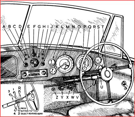
If the car is to be left outsider or in an unheated garage, the water must be drained from the system by opening the taps immediately under each cylinder head, and removing the radiator cap. When the cooling system has drained off completely, the engine should run for 3 or 4 seconds to ensure that all water has been expelled from the water chambers in the cylinder head and the water pump.
Figure 2. Position of the drain tap (L.H.) and sump plug.
As an alternative to this procedure, or if a heater is fitted, an Anti-Freeze (inhibited Ethylene Glycol) should be used to protect the cooling system during frosty weather. We recommend the use of Smith’s Bluecol non-corrosive Anti-Freeze to reduce corrosion to the minimum.
When changing over to Anti-Freeze, drain away sufficient water and replace by Bluecol. If the Anti-Freeze is added when the weather has already become cold, all the water should be drained from the cooling system, and the Anti-Freeze should be mixed with the correct proportion of water in a suitable container. If the Anti-Freeze is put directly into the radiator, it may take some time to mix with the water in the cylinder jackets, as the thermostat prevents circulation until the water in the jackets are hot.
The recommended proportions of Bluecol to water for your car are quoted below. With this Anti-Freeze in the cooling water, it is unnecessary to drain the system, even in the coldest weather, and one filling normally lasts the whole winter. Bluecol does not evaporate and it is, therefore, only necessary to top up with water in the usual manner.
Before adding the Anti-Freeze solution, make sure that all water hose clips are securely fitted and that the cylinder head nuts are tight. A label should also be fastened in a prominent position under the bonnet so that anyone who may have occasion to drain the radiator will be aware of the presence of the Anti-Freeze mixture.
|
Recommended Proportions Of Bluecol Anti-Freeze For Protection Against Various Degrees Of Frost. |
|||
|
Degrees Of Frost |
15 °F of Frost |
25 °F of Frost |
35 °F of Frost |
|
Proportion |
10% |
15% |
20% |
|
Quantity Of Bluecol |
2-pints |
3-pints |
4-pints |
|
Note: We recommend that you provide ample protection against sudden falls in temperature by using in your car the 20% proportion of Bluecol anti-freeze. |
|||
Lubrication
The importance of proper and regular lubrication of the car cannot be over-emphasised. In the design of a modern car, as much reliance is placed upon the presence and quality of the lubricating oils as is placed upon the quality and temper of the steels used. for its components. The manufacturer provides the latter – the owner is relied upon to provide the former. The properties of the lubricants used have been assessed and made full use of by the designers. If inferior grades are used they will not possess these properties, and breakdown will result – rapid wear and possible seizure of parts will follow, incurring heavy replacement expenses. Owners are, therefore, urged to use only the oils and greases recommended.
Regular lubrication is as important as proper lubrication, and it is suggested to owners that they develop the habit of carrying out a well-rehearsed drill, as detailed on Page 14 – at the intervals shown. This should be learned in connection with the lubricating chart which shows where the various filling plugs and grease nipples are located.
Lubrication Schedule
|
Every 200 Miles Or Weekly* |
|
|
Check Level Of Oil In Sump |
|
|
Check Level Of Water In Radiator |
|
|
Every 500 Miles Or Half-Monthly* |
|
|
(B) |
Grease steering connections and front suspension nipples |
|
|
Grease steering pinion universal joint |
|
|
Check tyre pressures |
|
|
Check acid level in battery |
|
Every 2,500 Miles Or Quarterly* |
|
|
(C) |
Change engine oil |
|
(D) |
Check level of oil in gearbox |
|
(E) |
Check level of oil in rear axle |
|
(F) |
Check level of fluid in brake fluid reservoir |
|
(G) |
Grease steering pinion shaft |
|
(H) |
Check level of oil in front suspension reservoirs |
|
(J) |
Grease steering column bearings |
|
(K) |
Grease gear control column |
|
(L) |
Grease brake and clutch pedals |
|
(M) |
Grease brake cable and linkage |
|
(N) |
Grease water pump bearing and oil fan spindle |
|
(O) |
Oil distributor and throttle linkage |
|
(P) |
Clean oil filter element |
|
|
Oil direction indicators |
|
(Q) |
oil gear control linkage |
|
Every 5,000 Miles Or Half-Yearly* |
|
|
(R) |
Grease front and rear hubs |
|
(S) |
Grease propellor shaft, universal joints and spline |
|
|
Grease tachometer drive gear |
|
|
Clean and reset sparking plugs |
|
|
Adjust brakes. Adjust clutch pedal. |
|
Every 10,000 Miles Or Yearly |
|
|
(T) |
Change oil in gearbox |
|
(U) |
Change oil in rear axle |
|
(V) |
Replace engine oil filter element |
|
(X) |
Grease dynamo rear bearing |
|
(Y) |
Remove sump and clean oil pump strainer |
|
(Z) |
Remove/replace, or clean, the tappet cover air vent filter felts |
|
* Or more frequently if necessary. |
|
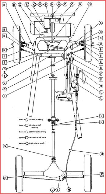
Figure 3. Lubrication Chart.
Recommended Lubricants
Engine 20 – 70 °F Wakefield – Castrol XL; Anglo – Essolube 30; Prices – Energol SAE30; Shell – Double Shell; Vacuum – Mobiloil A; Duckhams – Adcol NP30.
Engine Over 70 °F Wakefield – Castrol XXL; Anglo – Essolube 40; Prices – Energol SAE40; Shell – Triple Shell; Vacuum – Mobiloil BB; Duckhams – Adcol NP40.
Gearbox 20 – 70 °F Wakefield – Castrol XL; Anglo – Essolube 30; Prices – Energol SAE30; Shell – Double Shell; Vacuum – Mobiloil A; Duckhams – Adcol NP30.
Gearbox Over 70 °F Wakefield – Castrol XXL; Anglo – Essolube 40; Prices – Energol SAE40; Shell – Triple Shell; Vacuum – Mobiloil BB; Duckhams – Adcol NP40.
Rear Axle Over 20° Wakefield – Castrol Hypoy; Anglo – Essolube EXPEE Compound 90; Prices – Energol EP SAE90; Shell – Shell Spirax EP90; Vacuum – Mobilube GX90; Duckhams – Adcol Hypoid 90.
Grease Fittings* Wakefield – Castrolease Medium; Anglo – Esso Grease; Prices – Belmoline D; Shell – Shell Retinax C; Vacuum – Mobilgrease No. 4; Duckhams – Adcol H.F.G.
Suspension Reservoirs Wakefield – Castrol XXL; Anglo – Essolube 40; Prices – Energol SAE40; Shell – Shell Triple; Vacuum – Mobiloil BB; Duckhams – Adcol NP40.
Grease Fittings** Wakefield – Castrolease Heavy; Anglo – Esso Grease; Prices – Belmoline C; Shell – Shell BB Grease; Vacuum – Mobilgrease No. 4; Duckhams – Adcol H.B.B.
Brake Cables Wakefield – Castrol Brake Cable Grease; Anglo – Esso Graphite Grease; Prices – Rangraphine; Shell – ; Vacuum – Mobile Graphite No. 3 Grease; Duckhams – Adcol Z.N.Q.L. K.G. 16.
Brake Fluid Girling Crimson Brake Fluid.
Universal Joints Wakefield – Castrol D; Anglo – Essolube Gear Oil 200; Prices – Energol 140; Shell – Shell Spirex C; Vacuum – Mobiloil C Oiline N.J.O. 160 or, Mobilube 2300 or 300; Duckhams – Adcol C.G.1 H2 Gear Oil.
General Lubrication^ Wakefield – Castrol XL; Anglo – Essolube 30; Prices – Energol SAE30; Shell – Double Shell; Vacuum – Mobiloil A; Duckhams – Adcol NP30.
* Suspension, Tacho. Drive, Steering Gear; ** Hubs, Water Pump, Chassis Etc.
^ Oil Can Use – Fan Spindle Bearings, Door Hinges Etc. (See Page 23).
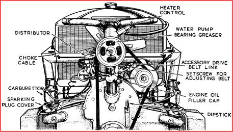 Engine Lubrication
Figure 4. Front view of engine.
The engine oil filler cap and the dipstick are at the front of the engine, and are easily accessible when the bonnet is lifted.
Check the engine oil level before starting the engine and always with the car standing on level ground. Remove the dipstick, wipe it on a piece of clean cloth, and then measure the level by pushing it right home again, withdrawing it and noting the level to which it is ‘wetted’ by oil. Add sufficient oil to keep the level up to the ‘F’ or full mark. As a general guide it can be taken that ¼ in. on the dipstick is equivalent to 1 pint of oil.
The low mark on the dipstick indicates the safety point below which the oil level should not be allowed to fall.
It should be particularly noted that if the oil level is checked immediately after the engine has been run, a false reading will be obtained, as a certain amount of oil is ‘splashed’ about the crankcase and is carried in the full flow filter and oil cooler. Topping up in these circumstances will, of course, result in overfilling.
Take extra care to see that any containers used to fill the sump are scrupulously clean. Although an oil filter is fitted the exclusion of dirt from this engine is particularly important, as it may find its way into the hydraulic tappet units and impair their efficient and noiseless operation.
Changing the Engine Oil is preferably done after a good run, when the oil is warm and flows freely. The sump plug is on the left hand side, easily accessible from the front of the car. Make certain that all the old oil has drained away before replacing the plug and refilling with oil. If the oil filter has been removed for cleaning at the same time, refill the sump to a level of about ¼- in. above the ‘F’ mark on the dipstick, to compensate for oil drained from the filter.
Cleaning the Oil Filter is best done at the same time as the engine oil is being changed. First unscrew the drain plug ‘A’ (see Figure 5) until about ¼-in.of thread is showing which will allow oil in the filter to drain back into the sump. Remove the filter body and element by unscrewing the central bolt – this cannot be removed but is lifted away with filter element and body. In lifting these away take care to tilt the body (open end highest) slightly to prevent any oil remaining inside from spilling on to the top of the engine. Clean these parts thoroughly in petrol and let them dry.
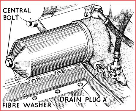 In replacing the filter, make sure that the rubber sealing
ring for the body is in good condition (replace if not) and that the body seats
squarely upon it, before screwing home the central bolt tightly. Then screw
home the drain plug ( A).
In replacing the filter, make sure that the rubber sealing
ring for the body is in good condition (replace if not) and that the body seats
squarely upon it, before screwing home the central bolt tightly. Then screw
home the drain plug ( A).
Figure 5. Oil filter
Gearbox Lubrication
Access to the gearbox filler and dipstick is obtained behind the radiator when the bonnet is lifted. Remove the dipstick and measure the oil level in the usual way. If necessary, add sufficient oil to restore the level to the ‘F’ or full mark. The use of a funnel will be found helpful for this purpose.
Changing the gearbox oil is best done after a run when the oil is warm and flows freely. The drain plug is in a horizontal position on the left-hand side of the gearbox, and there is a key in the tool kit for removing it.
Leave the car with plug removed, allowing adequate time for the oil to drain thoroughly before replacing and refilling the gearbox to the correct level.
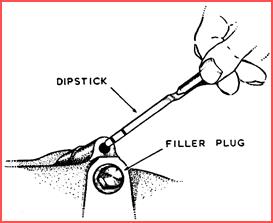
Figure 6. Gearbox filler plug and dipstick.
Rear Axle Lubrication
The correct lubrication of the hypoid rear axle is of the utmost importance. On no account must oils other than those recommended by us be used, and these oils must not be mixed one with the other. AFTER THE FIRST 2,000 MILES DRAIN THE AXLE, and refill with the brand of oil you intend to use. Thereafter replenish ONLY WITH THIS BRAND OF OIL – if a change is desired. the axle must again be drained and refilled with the new brand. The combined filler and level plug is in the rear cover of the axle and can be removed by a special square key, provided in the tool kit. Drain the axle after a run, when the oil is warm, and allow adequate drainage time before refilling. The filling and changing of oil in the rear axle is, under the best conditions, an awkward and dirty job for an owner to undertake. He is well advised to allow a service station to do it, but should insist on the aforesaid instructions being carried out, and should make sure that one of the recommended HYPOID OILS, where possible from a sealed container, is used.
Steering Connection Lubrication
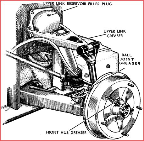 Greasers are provided for the lubrication of the
steering connections at the two ball joints of each steering rod. Access to
these can be gained when the bonnet is lifted (Figure 7). Give two or
three strokes of the grease gun to each greaser.
Greasers are provided for the lubrication of the
steering connections at the two ball joints of each steering rod. Access to
these can be gained when the bonnet is lifted (Figure 7). Give two or
three strokes of the grease gun to each greaser.
Figure 7. Front suspension
Steering Rack And Pinion
Two grease nipples are provided on the outer case of the rack and pinion. It is very important that the rack and pinion are well lubricated at all times, as any dryness between the teeth will tend to cause heavy steering,
Brake Fluid Reservoir
This is mounted on the right-hand side of the chassis behind the radiator, and is accessible on lifting the bonnet. The level of the fluid should be inspected at the recommended mileage and restored to about one inch from the top of the container. On no account use any fluid other than that recommended.
Brake Gear Lubrication
There are four greasers provided for the lubrication of the brake operating gear. They are mounted on the pedal, the rear axle compensator, the rear brake cable, and the hand brake cable (see Lubrication Chart, Figure 3). The last of these can be reached on opening the bonnet, but the other three are only accessible from below the car. It is a good plan when lubricating these points to jack up the right-hand side of the car, as it greatly improves access to them. Particular importance is attached to the regular and thorough greasing of the rear brake cable and the rear axle compensator – neglect of these items will impair the efficiency of the braking system. As a special graphited grease is required for the cables (see Recommended Lubricants) which means cleaning out the grease gun and refilling with this grease, owners may prefer to allow their service station to attend to these two points.
Water Pump Bearing
Access to the greaser for the water pump bearing is obtained through one of the four holes in the drive pulley (see Figure 4). One or two strokes with the grease gun at the recommended mileages should be given.
Tachometer Gearbox
This is situated at the rear of the dynamo where the drive for the tachometer is taken from the dynamo spindle gear. It is important that the gearbox is kept filled with grease to ensure that the drive gear receives adequate lubrication.
Rear Hub Bearings
The greaser for each rear hub is situated at the end of the axle tube and is accessible from underneath the car (see Figure 8). Give each two or three strokes with the grease gun at the recommended mileage. Grease issuing from the small hole above the nipple indicates that there is sufficient grease in the bearings.
Greasing Front Hubs
In the case of both front and rear hubs, great care should also be exercised when greasing, to avoid injecting too much grease, as there is a danger that any excess may exude on to the brake linings, and impair their efficiency. The front hub greasers are easily reached by removing the front hub caps.
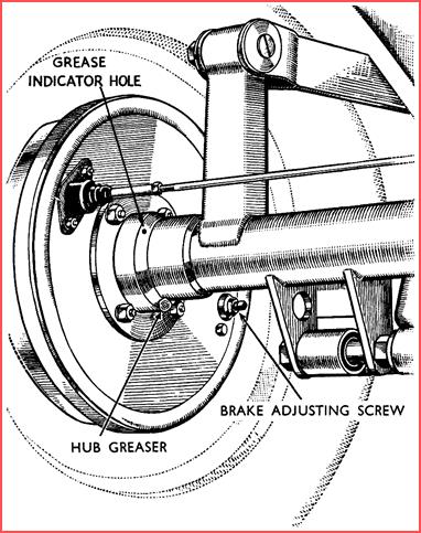
Figure 8 Rear hub and brake adjuster.
Propellor Shaft
Greasers are provided on the centre and rear universal joints and on the centre joint spline (see Figure 9). These should be lubricated every 5,000 miles, or more frequently if necessary.
Grease must not be used for this purpose, and attention is drawn to the correct grade of lubricant as indicated on Page 16.
The front universal joint, which is a Layrub coupling, needs no lubrication.
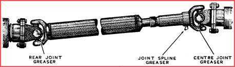
Figure 9. Transmission.
Minor Lubrication Points
Periodic lubrication with an oil can of various items of the car will be well repaid in that these items will remain sweet and quiet in operation.
Chief among these is the throttle linkage, follow this through from the pedal to the carburettors, oiling each pin and sliding surface, not forgetting the moving joints of the carburettors themselves. The inner member of the Bowden cable should also be oiled. At the engine end oil the cable for about 1½- in. where it emerges from the conduit and at the pedal end; with the pedal pressed hard down, similarly oil the cable where it emerges.
Then operate the pedal up and down two or three times to help the oil work into the conduit at each end. The ball joints at each end of the control rods between the gearbox and the steering column gear lever also require lubricating occasionally.
Occasional attention should be given to various hinges on the body in order to keep them operating smoothly. The door hinges, which are the most important, are easily accessible from outside the car. Squirt a few drops of oil on to each end and move the door to and fro so that the oil works in, then wipe off any surplus from the outside. Treat the bonnet hinges in the same way.
MAINTENANCE
 After the first 500 miles, and subsequently at the
recommended mileages, the four sparking plugs should be removed for cleaning
and re-setting the electrode gaps. Each one is enclosed by a plastic cover
attached to the end of the lead: this is removed by turning it in an
anti-clockwise direction until it springs out of the metal cover enclosing the
sparking plug: then withdraw it completely.
After the first 500 miles, and subsequently at the
recommended mileages, the four sparking plugs should be removed for cleaning
and re-setting the electrode gaps. Each one is enclosed by a plastic cover
attached to the end of the lead: this is removed by turning it in an
anti-clockwise direction until it springs out of the metal cover enclosing the
sparking plug: then withdraw it completely.
Using the box spanner provided in the tool kit, unscrew the sparking plug. When lifting the sparking plug clear from the engine, take care not to lose the copper asbestos washer. When the four plugs are out, examine them. The hard carbon deposit should be removed from each plug by brushing it with a wire brush, or scraping it with a penknife or other similar tool. Finally, check the electrode gap with your feeler gauge. This should be 0.020 to 0.025 in. Adjustment should be made by bending the side electrode towards the centre one.
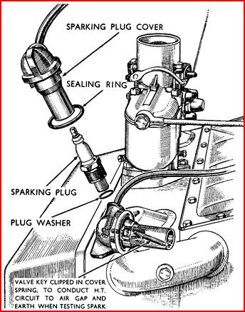
Figure 10. Sparking plugs.
In replacing the sparking plugs, screw them home as far as possible with the fingers, having made sure that the copper asbestos washer is in position. Then tighten up with the box spanner. Before replacing the plastic cover make sure its rubber seal is correctly in position; lower the cover carefully over the plug, holding it centrally in the hole aligning the two lugs on its side with the mating slots. Finally, press it home and turn about one-eighth of a turn in a clockwise direction.
Adjustment Of Brakes
Adjustment of the brake shoes will be necessary as wear takes place. This will be indicated by the ‘free’ movement of the brake pedal becoming excessive.
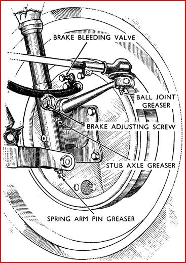
Figure 11. Front brakes.
Shoe adjustment is done individually at each wheel by the single adjusting screw on each brake carrier plate. Jack the car up at one side until front and rear wheels are free of the ground. The adjusting screw of the front brake is located as shown in Figure 11 and is turned with the use of a ⅜-in. Whitworth spanner. Spin the wheel in the rotation of FORWARD movement of the car, and at the same time tighten the adjusting screw until the brake shoe rubs and stops the wheel (turn clockwise for left-hand brake and anti-clockwise for right-hand brake). Then slacken back the screw until the wheel just spins freely. In the case of the rear brakes, the adjusting screw is located as shown in Figure 8, and is turned with the use of a ⅛-in. Whitworth open-end spanner. It clicks over notches as it is tightened in a clockwise direction: do this as far as it will go without forcing, until the shoes are binding on the drum. Then slacken off the adjusting screw for two notches when the drum should revolve without binding on the brake shoes.
Jack the car up at the other side and repeat the above procedure. Brake shoe adjustment should only be done with the drums cold.
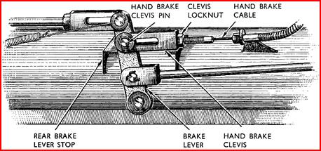
Adjustment Of Handbrake
 The handbrake normally requires no adjustment, as
the setting should be restored by the adjustment of the rear shoes. However, if
the handbrake lever can be pulled over seven notches, it will be necessary to
adjust its setting. As the efficiency of the footbrake can be effected by
incorrect adjustment of the handbrake we would ask the owner to note the
following instructions very carefully when carrying out this operation. The brake
mechanism (see Figure 12) is located at the right-hand side of the chassis
just to the rear of the centre cross member.
The handbrake normally requires no adjustment, as
the setting should be restored by the adjustment of the rear shoes. However, if
the handbrake lever can be pulled over seven notches, it will be necessary to
adjust its setting. As the efficiency of the footbrake can be effected by
incorrect adjustment of the handbrake we would ask the owner to note the
following instructions very carefully when carrying out this operation. The brake
mechanism (see Figure 12) is located at the right-hand side of the chassis
just to the rear of the centre cross member.
Figure 12. Handbrake adjustment.
The handbrake cable which emerges from its conduit at this point, is fastened to the upright lever by a clevis pin and locknut. Release the locknut and remove the split pin and clevis pin. Make certain that the brake lever is resting against the rear brake stop. Keeping the lever in this position, screw the handbrake clevis on to the cable until the rear of the elongated holes in the clevis mate with the hole in the lever. Replace the clevis pin and test. The handbrake lever should ‘click’ over four to five notches at this setting. Replace split pin and tighten the clevis locknut.
Adjustment Of Clutch Pedal
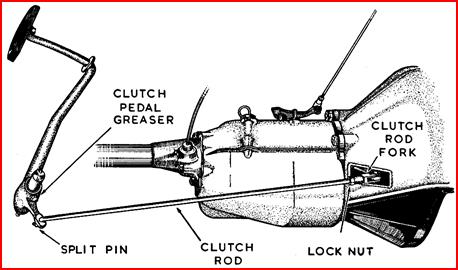 When depressing the clutch pedal, it should move
approximately 1-in. before the resistance of the springs is felt. Should this ‘free
movement’ become less or more than this, adjustment of the pedal is necessary.
This is effected by shortening or lengthening the link between the clutch pedal
and the clutch itself, access to which is obtained underneath the car.
When depressing the clutch pedal, it should move
approximately 1-in. before the resistance of the springs is felt. Should this ‘free
movement’ become less or more than this, adjustment of the pedal is necessary.
This is effected by shortening or lengthening the link between the clutch pedal
and the clutch itself, access to which is obtained underneath the car.
Figure 13. Clutch pedal adjustment.
Remove the split pin from the rod at the rear end of this link, and after having slackened off the locknut, screw the rod either in or out of the fork, depending on whether the free movement of the pedal has been excessive or insufficient. Screwing in will reduce the ‘free movement’ on the pedal and screwing out will increase it. The rod should be adjusted until the pedal movement is approximately the desired 1-in. Then replace the rod and the split pin, and tighten the locknut on the rod.
Shock Absorbers
The Woodhead-Monroe shock absorbers are factory sealed units, and no topping up is required. The occasional application of a preservative oil to the surface of the lower cylinders of the shock absorbers is recommended.
TYRES
 Tyres should be maintained at the correct pressure of
26 lbs. per sq. in. and should be cheeked every week, This should, of course, be
done when they are at normal temperature.
Tyres should be maintained at the correct pressure of
26 lbs. per sq. in. and should be cheeked every week, This should, of course, be
done when they are at normal temperature.
The tyres should be examined occasionally for flints or other road material, tacks, etc., which may become embedded in the tread. Oil should not be allowed to get on the tyres. If any should accidentally do so this should be cleaned off by using petrol sparingly.
Causes Of Premature Tyre Wear
Speed. Car owners vary greatly in the speed at which they habitually drive. The rate of tread wear at 70 m.p.h. is more than double that at 40 m.p.h.
Rapid Acceleration. During wheel slip caused by rapid acceleration excessive tread wear takes place, due to the abrasion of the tyre against the road surface.
Braking. Some owners habitually ‘drive on’ the brakes. It is established that when this practice is adopted, and especially if stops are frequent, the rate of tyre wear increases considerably.
Steering Out Of Track. This will cause the front tyres to wear rapidly. The steering track should be set at parallel, though up to ⅛-in. TOE OUT is permissible (measured on line of hubs at rim diameter).
Cornering. Driving round a curve even at 35 miles per hour can create a centrifugal force equal to twice the normal load carried by the tyres. This is in-clined to cause tyre side wall stretch which will, in time, weaken the tyre walls.
Under-Inflation. Ascertain that the correct pressure is maintained in your tyres, Running for a considerable distance with soft tyres will result in the cording on the tyre walls being overstressed. Remember that even under normal driving conditions a tyre will lose 2 to 3 lbs. pressure per week.
Over-Inflation. If a tyre is over-inflated the centre of the tyre tread only contacts the road surface. Road friction is concentrated on this part of the tread and rapid wear takes place.
SERVICE INFORMATION
Decarbonising
 The only sure indication of the need for
decarbonising, is the performance of the engine, and the mileage covered before
this becomes necessary varies considerably, depending upon the conditions under
which the car is used.
The only sure indication of the need for
decarbonising, is the performance of the engine, and the mileage covered before
this becomes necessary varies considerably, depending upon the conditions under
which the car is used.
The normal symptoms which indicate that decarbonising is necessary are excessive pinking and loss of performance, often coupled with lack of compression which results from valves failing to seat correctly. As a general guide, we would recommend that as long as the engine performance is satisfactory, you leave well alone. There are, however, several authorities who consider that early decarbonising after, say, the first 2,500 miles of the engine life is advantageous. The question is, therefore, left open for the owner to act as he thinks fit, and we would respectfully suggest that the guidance of the Jowett Main Agent, with knowledge of local conditions, quality of petrol available, etc., is sought.
It is appreciated that most owners will prefer to have the work carried out by specialist mechanics, and we would strongly recommend that the work should be done by a Jowett Main Agent, but for those who wish to carry out the work themselves, the method is outlined as follows:–
Drain off the cooling system, remove the front road wheels, dynamo, carburettor petrol pipe, throttle controls, and carburettors.
Remove the rocker covers, tappet covers, and rocker assemblies, withdraw the push rods and tappets and place them in a suitably marked container so that they can be refitted in their original positions again. It is particularly important that the tappets are placed in a clean container away from other parts, and that the tappet pistons are stored with the appropriate hydraulic unit, as these must not in any circumstances be ‘crossed’.
Remove the water transfers. Remove the cylinder heads.
Valve springs are held in position by split cones and collars, which can be removed once the valve springs are compressed. Turn the crankshaft until two of the pistons are at T.D.C. position, then fill the remaining cylinders with clean cloth to prevent any chips of carbon from falling into them. Scrape the piston crown and the carboned portion of the cylinder liner flanges using a blunt screwdriver or similar tool, and taking care to prevent carbon from falling between the liners into the cylinder block.
Remove the cloth from the cylinder bores, and turn the crankshaft until the two remaining pistons are at T.D.C. Treat these in the same way as for the first two pistons dealt with.
Remove the sparking plugs from the cylinder heads, scrape the combustion chambers, and wipe clean as soon as the operation is completed. Scrape clean the valve ports, but be careful to avoid scratching the valve seats. When completed, wipe clean with a petrol-damped cloth. Do not polish any parts with an abrasive or emery cloth, as particles of these may during assembly, enter the cylinder bores.
When finally cleaning the head, make sure that all stud holes, push rod tubes, etc., are thoroughly clean.
Clean the carbon from the underside of the valve head as well as from the top: using a blunt knife and finishing with a petrol-damped cloth. If the cylinder head gasket is suitable for refitting both sides should be carefully cleaned.
Valve Grinding
The purpose of valve grinding is to ensure that the bevelled surfaces of the valve, and the valve seat in the cylinder head make perfect contact, so that the valve is gastight when seated. This is achieved by grinding the two surfaces together, taking care that each valve is ground into its appropriate seat. The valves should not be scratched or marked in any way to indicate the valve number.
Valve grinding consists of coating the bevelled face with grinding paste and refitting the valve in its guide, then, using a suction cup grinding tool spin the valve first in one direction, then in the other, using only a light pressure. From time to time lift the valve off its seat and re-seat it in a slightly different position. If the valve seats are only slightly pitted, only a fine abrasive compound will be needed but if badly pitted commence with a coarse paste, finishing off with a fine paste. When correctly ground the mating surfaces of the valve and seat should present an even clean grey matt appearance. Before replacing the valves care should be taken to see that every particle of grinding compound has been removed both from the valves and the seats and valve ports.
Re-Assembty
When re-assembling, enter the valve into its guide, place the valve spring and collar in position, lightly oil the valve stems, and push the valve home. Hold the valve in position and press down the spring and collar using a standard compression tool, insert the split cones into the valve groove and ease off the tension on the spring, locking the collar into position.
Replace cylinder head using a gasket sealed with gasket cement and tighten the cylinder head nuts, in rotation, in the order shown in Figure 14.
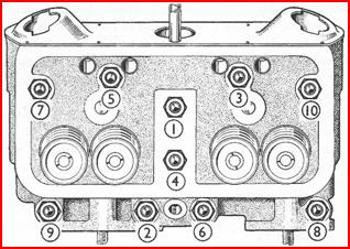 The torque loading for the cylinder head nuts is 42 lb.
ft.
The torque loading for the cylinder head nuts is 42 lb.
ft.
Figure 14. Tightening order cylinder head nuts.
Wash the hydraulic tap-pets thoroughly in clean petrol, allow them to dry in air, and refit into the crankcase. Fit the push rods and rocker shafts. While the tappets are still dry of oil, set the push rod adjustment so that, with the spring in the tappet piston fully compressed there is between 0.060-0.080-in. (1.5 mm.) clearance between the face of the rocker and the valve stem. Note: When turning the engine to set the tappets turn in an anti-clockwise direction, otherwise the tappet will fill with oil and cause incorrect setting.
Now remove the sump and thoroughly clean the oil pump filter gauze and the interior of the sump itself. Under no circumstances must cloth be used for cleaning internal engine parts as loose threads or fluff adhering to the various surfaces tend to collect and cause a blockage in the lubrication system.
Replace sump and refill with engine oil.
Run the engine until the thermometer registers a temperature of approximately 75 °C., check the flow of oil from the rocker shaft assembly, which should be approximately 60 drops per minute then, again, tighten up the cylinder head nuts. Finally refit the rocker covers, and check for possible oil leaks.
Engine Tuning
The following notes on tuning the engine may be helpful to the owner who wishes to carry out this work himself.
 The contact breaker gap should be checked and set at
0.010-0.012-in. (0.25-0.30 mm.).
The contact breaker gap should be checked and set at
0.010-0.012-in. (0.25-0.30 mm.).
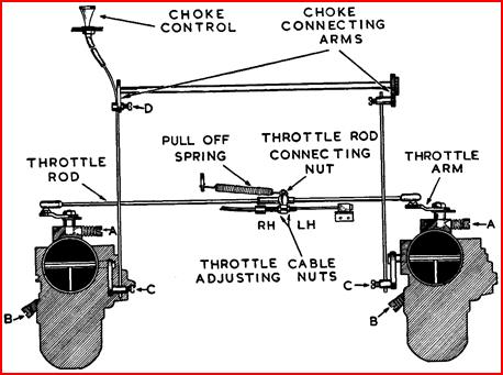
Figure 15. Carburettor adjustment.
The plug point gaps should be checked and set at 0.020-0.025- in. (0.5-0.6 mm).
The Suction and Centrifugal Ignition Advance Mechanism must work perfectly freely. This point should be very carefully checked.
Ignition timing should be set at T.D.C. to ⅜-in. A.T.D.C. on the flywheel subject, of course, to final adjustment on road test, and to the type of fuel available. Slight pinking on part throttle, at low speeds, is permissible, but if full throttle pinking occurs the ignition timing should be retarded slightly. It should not normally be necessary to retard the ignition later than ⅜-in. A.T.D.C.
Two Zenith 30 V.I.G.5 carburettors are fitted. All adjustments on these are made at the time of manufacture, other than the idling adjustment. After the first 500 miles, when the engine begins to lose its initial stiffness it may tend to idle at too fast a speed. This may be adjusted by means of the throttle stop screw ‘A’ (see Figure 15) and the air regulating screw ‘B’ on each carburettor, the latter enriches the mixture when turned clockwise and weakens it when turned anti-clockwise.
If, with the engine warm, it idles too fast, slightly unscrew screw A on each carburettor an equal amount until a slower speed is reached. Do not t y to make the engine idle too slowly or it may easily stall in traffic. It may now be necessary to readjust the air regulating screw B slightly. If the engine is inclined to ‘hunt’ the mixture is too rich and must be weakened by turning the air regulating screw anti-clockwise until a regular ‘beat’ is achieved. It is most important that the screw on each carburettor is adjusted an equal amount.
Should, for any reason, the carburettors become out of adjustment and cause engine idling to be uneven, it may be necessary to reset the throttle and slow running, and to ensure that the carburettors are perfectly synchronised, which is of the utmost importance we recommend the following method of resetting be adopted:–
1. Remove pull-offspring (Figure 15).
2. Slacken off throttle cable adjusting nuts
3. Loosen throttle rod connecting nut allowing rods to slide freely in rod connector.
4. Turn out throttle stop screws ‘A’ until throttle arms are in the fully-closed position.
5. Now holding throttle arms in this closed position turn adjusting screws ‘A’ until they just contact the arms and then turn a further full turn. This ensures that both throttle plates are open exactly the same amount.
6. Again ensuring that the throttle arms are resting on screws ‘A’, re-clamp the throttle connecting rod by tightening carefully the throttle rod con-necting nut.
7. Turn the right-hand throttle cable adjusting nut until the throttle arms just start opening. Slacken nut back approximately one and a half turns and lock up left hand throttle cable adjusting nut.
Replace pull-off spring.
8. Screw in fully the air regulating screws without forcing and loosen out three-quarters of a turn which is the approximate slow running position.
9. Switch on and start the engine and allow to warm. If the engine speed is too slow turn screws ‘A’ equally in clockwise direction until the desired speed is obtained. If the engine refuses to run for any length of time and gradually dies, it indicates that the mixture is too weak. To enrich, turn screws ‘B’ inwards equally. If engine tends to ‘hunt’, the mixture is too rich, and screws ‘B’ should be turned outwards equally.
Choke Adjustment
It is essential that the choke mechanism is adjusted correctly if good starting from cold and a good petrol consumption figure is to be obtained.
To adjust:–
1. Slacken off screws ‘C’ (Figure 15), allowing choke wires to move freely in the strangler flap arms.
2. Ensuring the choke control knob is pushed in fully, slacken off screw ‘D’ on right hand side, and move choke connecting arms until maximum fulcrum position is obtained, which is approximately ⅛-in. above parallel with ground level.
Retighten screw ‘D’ in this position.
3. Holding the strangler flap levers forward ensuring that strangler flap is in full open position, tighten screws ‘C’.
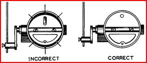
Figure 16, Chokes.
Finally, release air cleaner tube clip from top of carburettor and move tube to one side so that strangler flap is visible. Pull choke control knob out fully and ensure that strangler butterfly is seating correctly on fully closed position as shown in Figure 16.
Fast Idling Adjustment
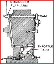 This mechanism, operated by a cam on the right-hand
carburettor, works in conjunction with the choke (see Figure 17) and increases
the engine speed when the choke is operated by opening the throttle plate
slightly.
This mechanism, operated by a cam on the right-hand
carburettor, works in conjunction with the choke (see Figure 17) and increases
the engine speed when the choke is operated by opening the throttle plate
slightly.
Right: Figure 17. Fast idle adjustment.
To adjust:–
1. Slacken off screw ‘E’ and move lever’ ‘F’ upward until the lever contact opens the throttle plate slightly when the choke is operated, holding arm in this position tighten screw ‘E’. It is essential that the engine speed is not excessive when the choke is operated.
Cleaning Fuel System
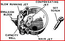 To clean carburettor bowls and jets, unscrew the set
screws (see Figure 18) holding the bowls to the carburettor body and
lift the bowls away. Remove the float, screw out the main and compensator jets
using the square end tip of the set screw illustrated. Remove remaining jets
with screwdriver.
To clean carburettor bowls and jets, unscrew the set
screws (see Figure 18) holding the bowls to the carburettor body and
lift the bowls away. Remove the float, screw out the main and compensator jets
using the square end tip of the set screw illustrated. Remove remaining jets
with screwdriver.
Figure 18. Cleaning carburettor jets.
Remove emulsion block by unscrewing the five holding screws taking care not to damage the gasket. If damaged in any way replace the gasket. Wash out jets and bowl and emulsion block in petrol and blow out thoroughly. Reverse above procedure to reassemble.
Cleaning Petrol Filter
All petrol entering the carburettors must go through the Zenith plate type filter and it is essential that it is kept in a clean condition. To carry out the cleaning operation, remove the glass bowl by unscrewing the bowl retaining nut (see Figure 19). Take care that the cork sealing washer does not get damaged in any way. If damaged replace. Unscrew plate filter knurled nut and slide the filter downwards off the centre stud. Wash filter and bowl out thoroughly in petrol, blow out and replace.
Petrol Tap .
A two-way petrol tap controls the petrol feed from the main and auxiliary tank and also cuts off the petrol supply completely if required. To turn off the petrol supply completely move lever to the straight down position as shown in Figure 20.
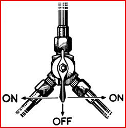
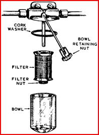
Figure 19. Petrol filter Figure 20. Petrol tap.
Tracing Starter Trouble
Failure of the engine to start is usually due to a fault in the petrol feed or ignition system. After having made quite certain that the ignition has been properly switched on and that there is petrol in the tank, we would suggest that the systems are checked in the following manner, starting first with the ignition.
Ignition System
Remove a plug cover and, into the spring within its open end, clip the brass tyre valve key (which is provided in the tool kit) so that its end is flush with the open end, of the cover. Lay the cover on a metallic part of the engine as shown in Figure 10. Crank the engine when a spark should jump across the skirt of the cover between the key and, the metallic surface. If a spark does occur, the ignition system is in order and the fault may be in the sparking plugs. Remove these and clean and adjust to the correct gap. If, however, no spark occurs, the ignition system is at fault and further investigation is required.
Remove the wire marked (S.W.) from the bottom of the coil and with the ignition switched on touch the terminal end to a metallic part of the engine. If a spark does not occur it indicates a faulty wire or connection between the coil and switch, or the switch and the battery and these should be examined carefully to locate the trouble. If a spark did occur on the above test remove distributor cover and examine the contact breaker points. If they are worn or pitted, clean and adjust to correct gaps.
Petrol System
Check that the choke mechanism is working correctly and that both strangler flaps are closing fully when the choke control is pulled out. Remove one of the carburettor bowls and switch on the ignition. The pump should then start to operate (indicated by a repeated ‘click’ inside the pump) and pump petrol past the open needle valve at the carburettor from which the bowl has been removed.
If the pump operates but no petrol appears at the carburettor remove the petrol filter bowl and clean out the filter element as shown in Figure19, and also the petrol pump filter as shown in Figure 22. If, however, the pump fails to operate when the ignition is switched on, remove the pump cover and clean the points.
After carrying out this operation, and the pump still fails to operate the owner would be well advised to contact his Main Agent or Service Station.
CARE OF BODYWORK
 Constant attention to the paintwork of a car is well
repaid – it will retain its freshness for years if it is kept clean and
occasionally polished. Cleaning is best done with a clean sponge and a copious
supply of water, especially when mud has been allowed to dry on the surface, it
should be washed and not rubbed off. After washing finish with a leather.
Constant attention to the paintwork of a car is well
repaid – it will retain its freshness for years if it is kept clean and
occasionally polished. Cleaning is best done with a clean sponge and a copious
supply of water, especially when mud has been allowed to dry on the surface, it
should be washed and not rubbed off. After washing finish with a leather.
Periodical polishing with a good cellulose polish will restore that fresh lustre to the surface. Do not be alarmed if some of the colour comes off on the cloth – it does no harm to the finish. After polishing, the surface should be protected by the application of a good wax polish – this wilt seal the surface for some time until further polishing is necessary. Grease and oil, and even tar, can be removed with a little petrol on a clean rag.
Chromium Plating
This is best cleaned by merely rubbing with a soft rag. If it is badly marked with tar, mud, or dead insects, use a little petrol or wash with warm soapy water. Do not use ordinary metal polish. as it contains abrasive matter which will ruin the plating.
Body Paintwork
If this should accidentally get chipped or scraped unsealed edges of paintwork will be left exposed to the atmosphere. To reseal the edges and prevent the damage spreading, touch in with cellulose. Small tins of cellulose of the same colour and grade used on works bodies can be supplied by your Jowett Agent.
Upholstery
Saddle soap may be used sparingly on leather upholstery or, alternatively, a good brand of furniture polish.
Hood Cloth
To remove any marks from the hood cloth brush over gently with a cloth damped in Trico-ethylene. Although petrol would probably remove the marks it is inclined to leave a faint tide mark when dry.
ELECTRICAL SYSTEM MAINTENANCE
 The electrical system is a Lucas l2-volt earth
return system, with compensated voltage control. A diagrammatic drawing of the
wiring system is shown on Page 46. It requires no attention beyond the routine maintenance
duties described below.
The electrical system is a Lucas l2-volt earth
return system, with compensated voltage control. A diagrammatic drawing of the
wiring system is shown on Page 46. It requires no attention beyond the routine maintenance
duties described below.
The Batteries
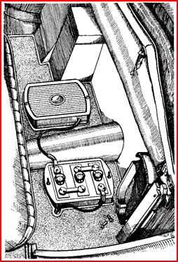 Two 6-volt units are carried behind the front seat. Access
is gained by pulling rear of seat forward (see Figure 21). Remove the
six vent plugs in the batteries so that the electrolyte is visible. This is a
solution of acid and water and it should always just cover the tops of the
plates. Keep the cells topped. up to this level by adding the distilled water –
use of a small glass funnel will greatly help this operation. After replacing
the plugs, wipe the top of the battery dry. Keep the terminals of the battery
clean. If they are corroded, scrape them clean and smear with petroleum jelly.
Occasionally check to see whether the batteries are firmly fixed by trying to move
them with your hands. If there is any move-ment, tighten up the fixing nuts.
Two 6-volt units are carried behind the front seat. Access
is gained by pulling rear of seat forward (see Figure 21). Remove the
six vent plugs in the batteries so that the electrolyte is visible. This is a
solution of acid and water and it should always just cover the tops of the
plates. Keep the cells topped. up to this level by adding the distilled water –
use of a small glass funnel will greatly help this operation. After replacing
the plugs, wipe the top of the battery dry. Keep the terminals of the battery
clean. If they are corroded, scrape them clean and smear with petroleum jelly.
Occasionally check to see whether the batteries are firmly fixed by trying to move
them with your hands. If there is any move-ment, tighten up the fixing nuts.
Figure 21. Batteries in position.
Petrol Pump
 This is an S.U. 12 V.
electric type pump positioned on the left-hand side of the scuttle behind the
radiator. Apart from cleaning the points if the pump tends to work rather
sluggishly after switching on the ignition no maintenance is normally required.
To clean the points, take off front plastic cover by unscrewing terminal screw
and cover nut. With an abrasive card clean points as illustrated in Figure
22. Great care should be taken not to force the outer point too far back
when cleaning as this may tend to bend the point arm. No point adjustment is
necessary.
This is an S.U. 12 V.
electric type pump positioned on the left-hand side of the scuttle behind the
radiator. Apart from cleaning the points if the pump tends to work rather
sluggishly after switching on the ignition no maintenance is normally required.
To clean the points, take off front plastic cover by unscrewing terminal screw
and cover nut. With an abrasive card clean points as illustrated in Figure
22. Great care should be taken not to force the outer point too far back
when cleaning as this may tend to bend the point arm. No point adjustment is
necessary.
Figure 22. Petrol Pump.
Distributor Lubrication And Adjustment
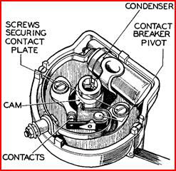 The Distributor is at the front of the engine on the
right-hand side. Re-move the cap by springing back the two securing clips on
the outside, then remove the moulded arm on top of the spindle and carefully
add a few drops of thin machine oil (do not remove the screw in the top of the spindle
as there is an oil way provided). Also put the spout of the oil can through the
central hole in the base plate through which the spindle passes and inject a
few drops of oil on to the governor mechanism. Put a light smear of grease on
the contact breaker cam and a spot of oil on the pivot on which the contact
breaker works.
The Distributor is at the front of the engine on the
right-hand side. Re-move the cap by springing back the two securing clips on
the outside, then remove the moulded arm on top of the spindle and carefully
add a few drops of thin machine oil (do not remove the screw in the top of the spindle
as there is an oil way provided). Also put the spout of the oil can through the
central hole in the base plate through which the spindle passes and inject a
few drops of oil on to the governor mechanism. Put a light smear of grease on
the contact breaker cam and a spot of oil on the pivot on which the contact
breaker works.
Figure 22. Distributor with cap removed.
Do not allow any oil to get on or near the contacts. To check the setting of the contact breaker, turn the engine by hand until the contacts are fully open. insert the gauge provided on the ignition screwdriver between the contacts. It should be a sliding fit when the gap is correct. To make the adjustment, keep the engine in the position giving maximum opening of the contacts and slacken the two screws securing the contact plate. Then move the plate until the gap is set to the thickness of the gauge, tighten the two screws and re-check the setting. If the contact faces are badly worn or pitted, they should be redressed using a fine carborundum stone or very fine emery cloth. Finish off with a cloth moistened with petrol and remove all traces of dirt and metal dust. Dirt between the points can cause misfiring and bad starting.
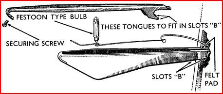 Direction Indicator
Lubrication
Direction Indicator
Lubrication
Figure 24. Direction indicator assembly.
Raise the arm of the direction indicator by operating the indicator switch and then supporting the arm in the horizontal position, move the switch to the ‘off’ position. Apply, by means of a brush or other suitable article, a drop of thin machine oil, such as sewing machine oil, to the catch pin between the arm and the operating mechanism. Also withdraw the screw on the underside of the arm and slide off the arm cover. Place the connecting wire to the bulb on one side, and apply a drop of thin machine oil to the lubricating pad at the top of the arm.
To replace the arm cover, slide it in an upward direction so that the side plates engage with the slots on the underside of the spindle bearing and secure with the screw.
Dynamo Lubrication
Unscrew the lubricator fitted at the rear end, lift out the felt pad and spring, and about half fill the lubricator with H.M.P. grease. Replace the spring and felt pad and screw the lubricator back in position.
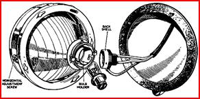
Headlamp Bulb Replacement
Each headlamp incorporates a Lucas light unit, which consists essentially of a reflector and front glass assembly provided with a mounting flange by means of which it is screwed in the body housing. The bulb, which is of pre-focus type, is located accurately in the rear of the light unit and is secured by a bayonet-fixed back-shell which also provides the contact to the bulb.
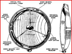
Figure 25. Headlamp rim and reflector.
To replace the bulb, remove front rim of the headlamp by unscrewing the securing screw and lifting off. Slacken off a few turns the four screws securing the light unit rim and turn complete assembly anti-clockwise until the screw heads can be cleared by the round end of the hole, in the unit rim. The assembly can then be lifted away to the extent of the two wires fastened to the bulb holder back shell. The bulb holder back shell, which i.e. held by a bayonet-type fixing, can be removed by turning anti-clockwise and lifting away from the bulb holder.
 Figure
26. Bulb replacement.
Figure
26. Bulb replacement.
The bulb can then be removed. The replacement bulb cannot be positioned incorrectly as a small cutaway on the bulb metal body mates with a key in the bulb holder. Refit bulb holder back shell. Replace light unit assembly rim over securing screws, making certain that dust excluding rubber is not disturbed and turn clockwise until the screws enter the narrow part of the holes in the rim. Tighten screws evenly. Replace front rim and secure.
Stop-Tail Lamp Bulb Replacement
To gain access to the stop-tail lamp bulb
turn back the rubber lip of the rim holder and lever out rim gently. Remove the
glass by turning back the inner rubber lip in the same manner. The bulb which
is of the bayonet-fixing twin filament type can then be removed. The bulb is
clearly marked ‘TOP’ on the stem and thig marking must be, of course, fitted
upper-most. To replace glass 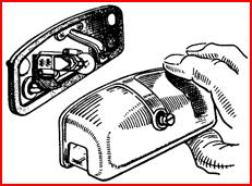 and rim work gently under the rubber lips.
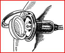 Figure 27. Stop-tail light. Figure
28. Number plate light.
Figure 27. Stop-tail light. Figure
28. Number plate light.
Number Plate Light Bulb Replacement
Remove light chrome cover by unscrewing centre screw. The bulb, which is bayonet-fixing type held in position by the spring contact, can then be removed and replaced without disturbing any other part of the assembly. When replacing the cover, do not over tighten the holding screw as this may tend to force the metal cover inwards and fracture the glass.
Headlamp Beam Setting
The lamps should be set so that the main driving beams are directed straight ahead, parallel with the road surface and with each other. If adjustment is required, remove the rim by removing the securing screw. Adjust the horizontal position of the beam, first by slackening the adjustment screws at each side of the light unit and moving the light unit backwards or forwards within the elongated slots until the correct position is obtained. Then set the vertical position of the beam by screwing in or out the adjustment screw located at the top of the light unit. The setting of the lamps can best be carried out by placing the car in front of a blank wall at the greatest possible distance, taking care of course that the surface on which the car stands is not sloping relative to the wall. It will be found an advantage to cover one lamp while setting the other.
Fuses
The fuses are mounted on the control box which is on the left-hand side of the dash under the bonnet: they are accessible without removing its cover. Two fuses are fitted, that marked ‘Aux’ protects the horn circuit, while that marked ‘Aux Ign’ protects all items wired in the ignition circuit, namely the warning lamps, the windscreen wiper, the direction indicator, the fuel gauge, the heater, and the stop lamp. When a fuse ‘blows’ all the items protected by it become inoperative: confirm this by removing the fuse, if it has ‘blown’, the broken ends of the wire will be visible inside the glass tube. Before replacing a blown fuse, inspect the wiring of the units that have failed for evidence of a short circuit or other fault which may have caused the trouble and repair it.
Spare fuses are provided and it is important to use only the correct replacement fuse, namely, 25-amps.
Tools
The tools provided with the car are stored in a locker immediately behind the driver’s seat. Access to these can be gained by moving the rear of the driver’s seat forward.
THE GUARANTEE
We give the following guarantee with our vehicles instead of the guarantee implied by statute, or otherwise, as to the quality or fitness of such machines for the purpose required; any such implied guarantee being in all cases excluded. In the case of vehicles which have been used for ‘hiring out’ purposes, no guarantee of any kind is given, or is to be implied. We guarantee, subject to the conditions mentioned below, that all precautions which are usual and reason-able have been taken by us to secure excellence of materials and work-manship, but this guarantee is to extend and be in force for six months only from the date of purchase, and damages for which we make ourselves responsible under this guarantee are limited to the supply of a new part to replace that which may have proved defective. In the case of a purchase through agent, the guarantee dates from the day of delivery to the purchaser, providing the vehicle has not been used in the meantime. We undertake, subject to the conditions mentioned below, to make good at any time within six months any defects in these respects. As vehicles are easily liable to derangement by neglect or misuse, this guarantee does not apply to defects caused by wear and tear, misuse, or neglect. We do not guarantee the specialities of other firms, such as tyres, lamps, electrical apparatus, etc., supplied with our, motor vehicles or otherwise.
Conditions Of Guarantee
If an alleged defective part should be found in a vehicle of our manufacture, it must be submitted to the dealer who effected the sale, or to a recognised Jowett agent or dealer. The Jowett agent or dealer will examine the same, and if he considers that there is a prima facie case for a claim he must send it carriage paid to the Works accompanied by an intimation from the sender that he desires to have it repaired free of charge under our guarantee.
If it is impracticable to hand the same to either a Jowett agent or a dealer he must himself send it to us carriage paid, giving the name of the agent from whom he purchased and the date of the purchase, and intimate his desire to have it examined and repaired free of charge under our guarantee. Failing compliance with the above, no notice will be taken of anything which may arrive, but such articles will lie here at the risk of the senders, and this guarantee shall not be enforceable.
The Term ‘Agent’
is used in a complimentary sense only, and those firms whom we style our Agents are not authorised to advertise, incur any debts, or transact any business, whatsoever on our account, other than the sale of goods which they may purchase from us; nor are they authorised to give any warrant or make any representation on our behalf other than those contained in the above guarantee.
JOWETT CARS LIMITED
INDEX
|
|
Page |
|
Page |
|
Anti-freeze, use of |
12 |
Lubrication |
39 |
|
Brakes: |
21 |
Bulb Replacement |
39 |
|
Filling Reservoir |
21 |
Electrical System Maintenance |
37 |
|
Brake Gear Lubrication |
21 |
Engine: |
31 |
|
Brake Adjustment, Foot |
25 |
Tuning |
31 |
|
Brake Adjustment, Hand |
26 |
Checking Oil Level |
17 |
|
Bodywork, care of |
36 |
Changing Engine Oil |
17 |
|
Batteries, care of |
37 |
Cleaning Oil Filter |
18 |
|
Bulb Replacement: |
39 |
Valve Grinding |
30 |
|
Headlamp |
39 |
Tappet Adjustment |
30 |
|
Tail and Stop Lamp |
40 |
Slow Running Adjustment |
32 |
|
Numberplate Lamp |
41 |
Starting |
11 |
|
Direction Indicators |
39 |
Starting Trouble, Tracing |
35 |
|
Carburettors: |
32 |
Fuses |
41 |
|
Slow Running Adjustment |
32 |
Front Suspension Lubrication |
20 |
|
Fast Idling Adjustment |
34 |
Gearbox: |
19 |
|
Choke Adjustment |
33 |
Checking Oil Level |
19 |
|
Cleaning Jets |
34 |
Draining |
19 |
|
Choke Control, use of |
11 |
Gear Change Positions |
9 |
|
Chromium Plating, care of |
36 |
Handbrake Adjustment |
26 |
|
Clock, setting |
8 |
Headlamp Beam, Setting |
41 |
|
Clutch Pedal Adjustment |
27 |
Heater Controls |
10 |
|
Cooling System: |
12 |
Hub Lubrication: |
21 |
|
Draining |
12 |
Front Hub |
21 |
|
Anti-freeze |
12 |
Rear Hub |
21 |
|
Controls: |
7 |
Instruments |
8 |
|
Driving |
7 |
Lubricant Recommendations |
16 |
|
Electrical and Lighting |
7 |
Lubrication Chart |
15 |
|
Decarbonising |
28 |
Lubrication Mileages |
14 |
|
Distributor: |
38 |
Lubrication Section |
16 |
|
Lubrication |
38 |
Oil Can Lubrication |
23 |
|
Adjusting Points |
38 |
Oil Filter |
18 |
|
Dynamo Lubrication |
39 |
Petrol Filter, Cleaning of |
34 |
|
Direction Indicators: |
39 |
Petrol Pump Filter, Cleaning of |
38 |
|
Petrol Pump Maintenance |
38 |
Cleaning and Adjustment |
24 |
|
Petrol Tap |
35 |
Steering: |
5 |
|
Propellor Shaft Lubrication |
22 |
Lubrication |
20 |
|
Rear Axle: |
19 |
Track Measurement |
28 |
|
Checking Oil Level |
19 |
Tachometer Drive Lubrication |
21 |
|
Draining |
19 |
Throttle Linkage Lubrication |
23 |
|
Running-in Period |
11 |
Tools |
42 |
|
Speedometer |
8 |
Tyre Maintenance |
28 |
|
Starting Trouble, Tracing |
35 |
Tyre Pressures |
28 |
|
Shock Absorbers |
27 |
Upholstery, Cleaning of |
37 |
|
Sparking Plugs: |
24 |
Water Pump Lubrication |
21 |
WIRING DIAGRAM
Key To Cable Colours (Figure 29.)
Headlights: 1. Blue Side Light 41. Red
2. Blue/Red Fog Light 42. Red/Yellow
4. Blue/White Panel light 44. Red/White
Ignition: 9. White Earth 57. Black
10. White Windscreen
16. White/Black Wiper 62. Black/Green
Ignition Fused: 17. Green
18. Green/Red
21. Green/White
22. Green/Purple
23. Green/Brown
24. Green/Black
Dynamo: 25. Yellow
29. Yellow/Green
Battery: 33. Brown
36. Brown/Blue
37. Brown/White
38. Brown/Green
38. Brown/Black
Note: In the case of two colours, e.g. Yellow/Green, the first colour is the principal colour, the second is the lesser colour (stripe).
Made and printed in Great Britain by Lund Humphries, Bradford and London.
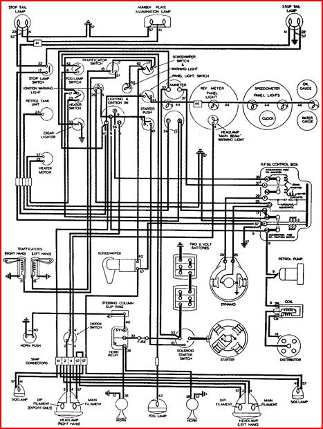 Figure 29. Lucas wiring diagram for
Javelin Jupiter.
Figure 29. Lucas wiring diagram for
Javelin Jupiter.