CHAPTER INDEX
Page No.
Preface 1
Method of Ordering Spares and Replacements 2
Useful Data 2
SECTION 1. Servicing Instructions 2
Driving Hints Running In 2
General Driving Hints 3
Gearbox Synchroniser 4
Guide to Maintenance 5
SECTION 2. Greasing 5
Lubrication Oiling 5
Lubricants 6
Engine 6
Engine Auxiliaries 7
Gearbox 7
Back Axle 7
Front Axle and Steering 8
SECTION 3. Valves – Twin Cylinder 8
Adjustments Valves – Four Cylinder 9
Steering – Twin Cylinder 9
Steering – Four Cylinder 9
Brakes 10
Clutch 11
Back Axle 11
Back Axle – Replacement of Shaft 11
Back Axle – Removal of Differential 12
Timing Chain 12
Ignition 12
Wheel Alignment 12
Gearbox Synchroniser 12
Front Hub 12
Removal of Gearbox 13
Cleaning Out Oil Sump 13
Engine Suspension 13
Removal of Cardan Shaft 13
Clutch Pedal Stop 13
SECTION 4. Decarbonising – Twin Cylinder 13
Overhauling Decarbonising – Four Cylinder 14
Valve Grinding 14
Engine Overhauling – Twin Cylinder 14
Engine Overhauling – Four Cylinder 14
Valve and Ignition Timing – Twin Cylinder 14
Valve and Ignition Timing – Four Cylinder 15
GENERAL CARE OF COACHWORK AND FITTINGS 16
PUBLICATIONS THAT ARE AVAILABLE 17
LIST OF TOOLS 17
THE JOWETT GUARANTEE 17
FIGURE INDEX
Page No.
8 h.p. Car Controls Fig. 1. 3
10 h.p. Car Controls Fig. 2. 3
Gearbox Synchroniser Fig. 3. 4
8 h.p. Lubrication Diagram Fig. 4. 6
10 h.p. Lubrication Diagram Fig. 5. 6
Engine Auxiliaries – 10 h.p. Fig. 6. 7
Gearbox Fig. 7. 7
Details Under Rear Seat Tray Fig. 8. 8
Front Axle Lubrication Fig. 9. 8
Line Drawing of 8 h.p. Steering Box Fig. 10. 8
Line Drawing of Front Axle Fig. 11. 9
Amidships View of Chassis Fig. 12. 10
Clutch Fig. 13. 11
Back Axle Fig. 14. 11
Engine Suspension Fig. 15. 13
10 h.p. Cylinder Head (order of tightening nuts) Fig. 16. 14
10 h.p. Cylinder Numbering Diagram Fig. 17. 15
Engine Timing Diagram to Flywheel Fig. 18. 15
10 h.p. Timing Diagram Fig. 19. 15
8 h.p. Timing Diagram Fig. 20. 16
10 h.p. Timing Illustration Fig. 21. 16
8 h.p. Oiling Chart Fig. 22. 18
8 h.p. Engine & Gearbox Line Drawing Fig. 23. 19
10 h.p. Oiling Chart Fig. 24. 20
10 h.p. Engine & Gearbox Line Drawing Fig. 25. 21
PREFACE
|
I |
n the issuing of this Instruction Book we have endeavoured to deal with the various points of lubrication, adjustment, and maintenance in a conversational manner, omitting, as far as possible, all technicalities, and we hope you will read your Instruction Book and thereby make yourself conversant with the details of your Jowett.
The whole range of Jowett pleasure cars is dealt with in this Book, both the twin and the four cylinder types; commercial models, however, are not referred to herein, but under a separate edition. It should be understood, therefore, that any instruction or advice in the following pages applies equally to either the twin or the four-cylinder car, for with the exception of the engine the two have very much in common. Wherever it has been necessary to differentiate in the text between the twin and the four, a clear indication has been given at the head of the paragraph in question to signify that the paragraph treats only with one type. A detailed chapter and figure index has been prepared for ease of reference.
We are at all times happy to assist Jowett owners with our advice on any matter concerning our products; in fact our Service Department at Idle exists primarily for that purpose.
Never confuse in one letter queries regarding the car and requests for spare parts, since these are dealt with by different departments. In every communication, give your engine number; this, together with the tappet setting, the ignition setting, and the firing order, is stamped on a metal plate riveted to the top of the timing case.
Finally, to obviate delay due to the absence of any member of the staff, always address your communications to the Company and not to individuals.
THE METHOD OF ORDERING SPARES AND
REPLACEMENTS
WE hold in stock, ready for immediate delivery, a complete range of parts of our vehicles that are liable to wear or damage by accident, and always dispatch• replacements same day as requested, if properly ordered and the necessary information given.
In ordering replacements, delay in receipt of same and trouble at these works will be avoided if care is taken in following the appended instructions.
1. ALWAYS QUOTE ENGINE NUMBER which is stamped on a metal plate fixed to the timing case.
2. ALWAYS QUOTE PART OR ASSEMBLY NUMBER printed in Spares List.
3. ALWAYS CONFIRM telegram or telephone Orders by letter immediately.
4. IF YOU CANNOT LOCATE PART NUMBER, adequately describe it in your order, and where possible send damaged part if not too bulky.
5. IN ALL CASES cash must be sent with Order, unless you have a credit on our books or the part weighs less than 15 lb., when it can be sent parcel post and C.O.D. This last does not apply to overseas users of our cars, who must always send cash with Order.
6. PACKING CASES ARE CHARGED, but credited on return. This applies to bulky articles only.
We frequently receive car parts unlabelled, and much delay is occasioned in consequence. When returning parts for repair, examination, or any other reason, be sure to pack them or label them in such a way that the ownership is easily discernible. We need your name, address, and engine number always. Help us to -help you by observing this rule; also, every letter you write, on whatever subject, should be headed — re engine number so-and-so.
REPLACEMENT UNDER OUR GUARANTEE
(Read terms of guarantee on Page 17 of this book).
All replacements claimed under our guarantee will be charged for in the usual way, but credit will be immediately allowed if, on investigation, the part is agreed to be faulty.
The part must be returned to these works, carriage paid, accompanied by an intimation that you desire it to be repaired or replaced under the terms of our guarantee.
Failing compliance with this, parts will lie here at owner’s risk, and our guarantee or any implied guarantee shall not be enforceable.
N 0 T E:
WHETHER YOU WRITE US, TELEPHONE US, OR TELEGRAPH US, ALWAYS GIVE US YOUR ENGINE NUMBER. THANK YOU!
USEFUL DATA
ENGINE Twin Four
Number of Cylinders 2 4
Bore 77 mm 63.5 mm
Stroke 101.5 mm 92 mm
Capacity 946 c.c. 1,166 c.c.
Horsepower 8 10
Maximum Brake Horsepower 17 31
@ 3,250 r.p.m. @ 4,000 r.p.m.
GEARBOX RATIOS
(Including Back Axle: All Models, 4.89 : 1)
Top 4.89 : 1
Third 7.30 : 1
Second 12.30 : 1
First 20.60 : 1
Speed on Top Gear at 1,000 r.p.m. – 15 m.p.h. approx.
CAPACITIES Twin Four
Petrol Tank 7 gallons 7 gallons
Radiator 7 qts 11½ qts
Engine Oil Sump 4½ pts 7 pts
Gearbox 2 pts 2 pts
Back Axle 1 pt 1 pt
STANDARD SETTINGS
Carburettor Jets (Twin) 25 Choke, 80 Main, 80 Comp., 50 Slow Run
Carburettor Jets (Four) 24 Choke, 90 Main, 80 Comp., 50 Slow Run
Valves (Twin) Inlet 0.006” Exhaust 0.006”
Valves (Four) Inlet 0.006” Exhaust 0.006”
Contact Breaker Gap 0.012”
Sparking Plug Point Gap 0.020”
Tyre Pressures (Twin) 22 psi Front 22 psi Rear
Tyre Pressures (Four) 24 psi Front 24 psi Rear
Lamp Bulbs – Head 12 V., 36 Watt, Side & Tail 12 V., 6 Watt
Wheelbase – 8’ 6”, Track – 4’ 0½”, Turning Circle – 36’
SERVICING INSTRUCTIONS FOR A NEW CAR
|
W |
hen you take delivery of your new Jowett, remember that Jowett Cars Limited have done their part to provide you with a trouble-free and economical motor car, and that now, the responsibility to a large degree rests with you to foster by wise treatment the characteristics we have built into your car.
There is no time in the life of a motor car when such careful attention should be given to its treatment as during the running-in period, which approximates to the first 1,000 miles of the car’s life; the particular attention of every owner is, therefore, directed to the chapter which follows these preliminary servicing instructions headed “Running-in.”
As soon as possible after the delivery of your new Jowett, it is a wise plan to give it a careful examination to see that it is complete and in order. Check over the equipment and tools (see Page 17 for details); examine levels of water in radiator, oil in engine, gearbox and back axle, and acid in the accumulator. The radiator should be full, replenish with rain water whenever possible. Oil levels are dealt with under their various headings in the text, see Chapter Index Section 2. The acid level in the accumulator should be maintained with distilled water in accordance with Lucas instructions issued with every car in a separate booklet. Become familiar with the functions of the instruments and controls on the dashboard by a study of illustrations 1 and 2. If you are not already conversant with Jowett cars, we suggest that this Instruction Book be carefully. studied as early as possible after you have become a Jowett owner.
RUNNING IN
|
D |
uring this period, the engine should never be allowed to work at above half-throttle. It is difficult to lay down set speeds which must not be exceeded, because a man may do an engine infinite harm by flogging it at 30 miles an hour on top gear up a fairly stiff rise, and yet not exceed the maker’s instructions of a 30 m.p.h. limit. By the same token, a man may brake down a long descent when he might with safety and advantage use his engine as a brake even though he exceeds considerably the 30 m.p.h. limit, because under such conditions the engine is not working hard, and the stresses which damage it are not imposed. The safest rule to follow is never to allow the engine to labour, but always to change down and use a lower gear when more power is required, thus keeping the throttle pedal never more than half depressed. As a guide, and subject to the limitations stated above, the approximate speeds at which it is safe to run a new car are : — Top gear, 25-30 m.p.h.; Third gear, 20-25 m.p.h.; Second gear, 12-15 m.p.h.; Bottom gear, 8-10 m.p.h., which figures apply to both 8 and 10-H.P. cars.
All owner-drivers who want the best out of their Jowetts will adhere to these rules regarding speed. The slight hardship of reduced speed suffered during the first 1 000 miles is amply compensated for by the sweeter running and the greater reliability and life of an engine carefully run in.
There are, of course, other things to watch besides speed when running-in. Lubrication must receive particular attention, the engine oil should be changed after 500 miles and again at 1,000.
It is advisable to use an upper cylinder lubricant to ensure that oil reaches the cylinder head. All greasing points must be attended to at least once a week, those on the front axle swivel pins once a day. The gearbox and back axle should be emptied of oil, flushed out and refilled at 1,000 miles. All body bolts should be tightened up at this period. Adjustment to the carburettor and the valves may be necessary at 500 miles; this should be attended to by your agent. The liberal use of the oil-can is recommended on clutch and brake pedal bearings, accelerator bearings and links, and the clutch thrust race. Your own agent and our Service Department here at Idle exist to help you over any difficulty you may encounter. Do not hesitate to approach them.
8 H.P. CAR CONTROLS
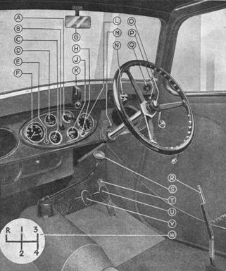
Figure 1.
A. Lighting & Ignition Switch M. Air Strangler
B. Starter Button N. Screen Wiper Motor
C. Petrol Gauge 0. Horn Push
D. Ammeter P. Headlamp Dipping Control
E. Ignition Warning Lamp Q. Trafficator Switch
F. Speedometer R. Handbrake Lever
G. Driving Mirror S. Gear Lever
H. Dash Light Switch T. Accelerator Pedal
J. Oil Pressure Gauge U. Foot Brake Pedal
K. Screen Opening Mechanism V. Clutch Pedal
L. Clock W. Gear Positions
10 H.P. CAR CONTROLS
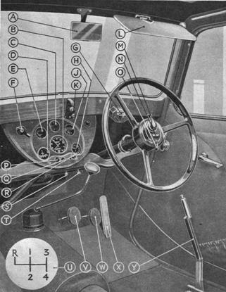
Figure 2.
A. Driving Mirror N. Horn Push
B. Speedometer O. Headlamp Dipping Control
C. Temperature Gauge P. Dash Light Switch
D. Ammeter Q. Ignition Warning Lamp
E. Petrol Gauge R. Air Strangler
F. Lighting & Ignition Switch S. Speedometer Trip Control
G. Screen Wiper Motor T. Clock Winder
H. Clock U. Gear Positions
J. Oil Pressure Gauge V. Clutch Pedal
K. Screen Opening Mechanism W. Brake Pedal
L. Sun Visor X. Accelerator Pedal
M. Trafficator Control Y. Handbrake Lever
GENERAL DRIVING HINTS
Before starting the car, always be sure that there is plenty of water in the radiator and oil in the engine. These two things are even more important than petrol in the tank, since to run out of petrol means at worst a walk, but to run out of oil or water means almost certain bearing seizure and an expensive repair bill.
Being satisfied on these points, to start the car, see that the gear lever is in neutral, pull out the air strangler to its fullest extent if the engine is cold, switch on ignition and depress starter switch. If the engine is hot, do not use the air strangler or the mixture will be too rich to start the hot engine. With everything in order, the engine should fire immediately, and it may be warmed up for a short period with the air strangler button half out, but under no circumstances must the car be run on the road with the button pulled out at all.
Easy starting is assured by the fact that the air strangler works in conjunction with a device which slightly opens the throttle. A helpful hint for cold weather starting is to keep the clutch pedal depressed when starting up, since this relieves the engine of having to turn the transmission gears.
If the engine fails to fire, make sure that there is petrol in the carburettor. Eight H.P. models fitted with A.C. pump feed may run dry in the feed pipe and carburettor float chamber if left for any length of time. It is then necessary to operate the petrol pump by hand. On the 10-H.P. models, the petrol pump is electrically operated and starts to function immediately the ignition is switched on, thereby assuring the presence of petrol in the carburettor float chamber whenever the engine is to be started.
The ignition is controlled automatically, being advanced or retarded pro rata to engine speed by a centrifugal governor mounted inside the distributor casing. Gear changing is simple and perfectly smooth. The positions of the gear lever are — Bottom to the left and up; second, straight back from first position; third, up, across neutral position, to the right and up again; top, right back from third position; reverse is obtained by moving the gear lever to the extreme left against the resistance of the reverse loading spring, then upward. A suggestion for gear changing to obviate any possibility of touching one of’ the other gears when making a change which necessitates crossing neutral position, is to give a diagonal push to the lever in the direction of the required gear position. For example, when changing from second to third on a four-speed gearbox, if three distinct pushes are given to the gear lever (up, across and up again), the first gear teeth may be fouled through the lever going a little too far on the first movement. If a push in a diagonal direction half up and half across to the right is given, this chance will be obviated.
A very effective clutch contributes greatly to the life of transmission parts and back axle. Its efficiency, however, must not be abused. Always stop dead before reversing.
The instrument panel is equipped with a switch controlling dynamo output to accumulator. This switch is combined with the lighting switch and has four positions reading from left to right as follows : — Half charge, a low rate of charge used for summer running when the demand on the battery for lighting and starting is low; medium rate, the winter position of the switch giving a higher charge to compensate for the extra load imposed during winter months; side lamps, a position which puts side and tail lamps into operation and permits full charge from dynamo to accumulator; head lamps, all lamps illuminated, charge rate — full charge. Never leave the ignition switched on when the engine is not running or you will risk burning out the coil and exhausting the battery. A warning lamp is provided on the dash panel which gives a red light if the ignition is not switched off when the engine stops.
The brakes are of the Bendix-Cowdrey balanced servo type, both hand and foot operating on shoes in all four drums. The whole braking system is fully compensated, and adjustment is simple. Full instructions are given under “Brake Adjustment,” see Chapter Index. During the running-in period, when the brake linings are bedding themselves down, more frequent adjustment than normal may be required. It is a wise plan to bear this in mind.
When draining water from the radiator and cooling system, first of all unscrew the radiator filler cap. This is necessary, as a spring-loaded ball valve now closes the overflow pipe and creates an air lock.
Like any other piece of mechanism, a Jowett will amply repay any care bestowed upon it. It is, of course, difficult to tabulate instructions regarding general servicing, since conditions under which particular vehicles work vary enormously. A Guide to Maintenance has, however, been arranged based on the assumption that the average weekly mileage does not exceed five hundred. If this mileage is exceeded the various functions will need to be carried out more frequently.
THE GEARBOX SYNCHRONISER
The last few years have seen big changes in gearbox design, most of which have had some bearing on easy changing. With a desire to maintain the simplicity and robustness of the straightforward gearbox, Jowett Cars Limited have avoided the complications involved by the synchromesh principle, and have solved the problem of easy gear changing without departing from a normal gearbox.
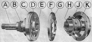
Figure 3.
A. Synchroniser Tail Shaft F. Outer Dog Clutch Member
B. Speedometer Drive Gear G. Spring Ring
C. Freewheel Outer Member H. Centre Driving Sleeve
D. Baulking Dog J. Inner Dog Clutch Member
E. Freewheel Inner Member K. Reverse Driving Dogs
On all 1937 10-H.P. four cylinder models and to special order on 8-H.P. cars, we are fitting a synchronising gear made under Warren Patents which marks another step forward in ease of control, superseding the orthodox freewheel and giving synchronised changes on all forward gears, either up or down, the action being : — Decelerate, declutch, change gear and accelerate without any special timing, pause or skill except one simple instruction — when declutching, press the pedal down to its fullest extent.
The synchroniser itself is a device bolted on to the rear of the gearbox, which operates in conjunction with the clutch pedal and breaks the drive from the propeller shaft to the gearbox when the clutch pedal is depressed. Upon declutching, therefore, both engine drive and over-run drive are isolated from the gearbox, and any change can be made in the forward range of speeds without noise and without pause. Upon releasing the clutch pedal, the engine drive is re-coupled to the gearbox, but the drive from the gearbox tail shaft to the propeller shaft does not engage until. the speeds of the two shafts are synchronised. This action is obtained by the use of a dog clutch controlled by a freewheel. So long as the speed of the propeller shaft is higher than that of the gearbox, the freewheel operates in a normal manner. The freewheel inner member on the gearbox tail shaft is permitted a few degrees of rotational float, which float is influenced one way or the other by the friction of the slipping freewheel outer member on the over-drive, or by the locking of the mechanism on the drive. On the over-drive, baulking dogs carried on the inner member fall in line with similar baulking dogs on the dog clutch proper, thereby preventing the drive being taken up. As soon as the gearbox tail shaft speed synchronises with that of the propeller shaft, the two members of the freewheel will be revolving at the same rate, and there will be, therefore, no friction between the members. The slightest further acceleration will influence the floating inner member and throw the baulking dogs out of line, permitting the dog clutch proper to engage and making the drive solid. This happens instantaneously at the moment of synchronisation.
The gearbox synchroniser, in addition to giving a synchronised gear change, also enables the car to freewheel if desired. A study of the foregoing description will show that freewheeling can be obtained at any time by pressing and releasing the clutch pedal provided that the accelerator pedal is not in operation at the same time. This means also that any gear can be preselected whilst the car is freewheeling, and engaged again by merely accelerating. The change from freewheeling to locked position when it is desirable to use the engine as a brake, is brought about by depressing the accelerator momentarily and releasing it again. One point in the interests of safety might be noted affecting the parking of the car on an incline. It is usual, when the car is parked on a steep gradient, to leave it in gear. The synchroniser, however, has the effect of putting the free-wheel into operation when the clutch pedal is depressed, thereby permitting over-run and nullifying the effect of leaving the car in gear. When declutching, prior to stopping on a gradient, it is, therefore, advisable to push the pedal only half way down. This will release the clutch sufficiently for the gear lever to be brought to neutral, but will not operate the synchroniser, since it is the last half of the clutch pedal’s travel which performs the latter function. Try experimenting with the parking of the car in the above condition in order to get the feel of the clutch pedal travel. The point where the synchroniser is affected can be felt because the mechanism is spring loaded and requires a slight further effort. Alternatively, make a practice of leaving the car in reverse gear since the fact of engaging reverse automatically cuts the synchroniser out of action.
So simple is the mechanism of the synchroniser that no trouble of any kind is likely to be experienced. Its function as a freewheel will effect a saving in petrol and in wear and tear of transmission parts. Its operation is entirely automatic and needs no skill.
GUIDE TO MAINTENANCE
DAILY
1. Check levels of petrol in tank, water in radiator, and oil in engine.
WEEKLY
1. Apply grease-gun to steering swivel pins (Figs. 9 and 11).
2. Check oil level in crankcase, and replenish (Page 6).
3. Give a few drops of oil to the hand and foot brake mechanisms, pedal shafts, and all points marked A on oiling chart (back cover) (Page 5).
4. Test Tyre pressures : — 8-H.P. Cars, front 22 lbs., rear 22 lbs.; 10-H.P. Cars, front 24 lbs., rear 24 lbs.
MONTHLY
1. Apply grease-gun to all grease nipples as shown on oiling chart (back cover).
2. Examine battery for level of electrolyte. Replenish, if necessary, with distilled water. Give Terminals a smear with grease.
3. Examine oil level in gearbox and back axle (Page 7).
4. Tighten up body bolts (Page 16).
5. Check brake adjustment (Page 10).
6. Refill hydraulic engine mountings (Page 13).
7. Give a smear of grease to all brake rod yokes (Page 5.
EVERY SIX MONTHS
1. Drain engine sump, wash filter in paraffin and refill with clean oil (Page 13).
2. Drain gearbox, flush out with paraffin and refill (Page 7).
3. Drain and replenish oil in back axle (Page 7).
4. Examine and take up any slack in timing chain (Page 12).
GREASING
|
T |
his one-time messy operation can be carried out on the present Jowett with ease and cleanliness. Accessibility of grease nipples has been carefully arranged, and a habit should be made of greasing once a week; it pays. Never use cheap grease, it may contain grit or water, both very injurious elements where ball bearings are concerned. Finally, see that grease is getting to the place where it is intended it should.
Car chassis, both twin and four-cylinder types, are practically identical insofar as greasing instructions are concerned, the only difference being that the twin has a grease nipple for the steering box whereas the four has Marles steering, which is lubricated with oil. The following instructions apply, therefore, to all cars. First the front axle. There are two greasers for each swivel pin, one for the top and one for the bottom bush. The track rod and the drag link both have nipples at each end for lubricating the ball and socket joints. The steering box on twin cylinder models has a nipple for lubrication of the gears. The hand-brake shaft on all models is grease lubricated, the nipple being found beneath the floor about 12 inches back from the rear edge of the offside front mudguard. Front and rear hubs are equipped with grease nipples, making the total number of 14 nipples on the twin and 13 on the four-cylinder car. The following procedure is recommended for the swivel pins. Place the Stevenson jack underneath one side of the car and raise it to its limit. Now apply the grease-gun to the nipples feeding the swivel-pin bushes on the side raised. Lower the car until the wheel almost touches the ground and, in this position, swing the steering wheel from lock to lock several times to ensure even distribution of the grease in the bearings. Give a full charge to the nipples before lowering the wheel to the ground. Proceed similarly with the other side of the car.
Periodical greasing at set intervals is advisable, and we recommend that swivel pins be attended to once a week, hubs every 5,000 miles, and the rest of the points once a month. When greasing hubs, take the load off the wheel by jacking up the car, and swing the wheel round to distribute the grease during the operation.
The brake-rod yoke ends require smearing with grease periodically to protect them from water and rust. There are three yokes attached to the link levers at the off-side end of the front axle close to the spring. Underneath the floorboards at the off-side of the car, the centre compensating mechanism will be found where there are four yokes to grease. On the back axle, near the off-side spring seat, a similar link to that on the front axle is located; three yokes need attention here. It is essential that grease be used on these brake-rod yokes, because if they are allowed to rust up, uneven braking will result.
Two other places where grease is used as a lubricant are sliding roof runners and seat runners. An occasional smear will keep the slides in order.
It is important when greasing to make sure that in every case greased is being forced right into each bearing. Never be satisfied until you see grease exude from both ends of the bearing. Sometimes it is found that a nipple becomes clogged, due perhaps to the ingress of foreign matter. To clear a clogged nipple, all that is necessary is to screw it out and heat it gently over a gas jet. Do not over-heat, or the spring which operates the ball valve will be damaged.
The grease to use in every case is either Castrolease Medium or Duckham’s Adcol HBB grease; either is suitable, in conjunction with the grease-gun supplied with the tool kit.
OILING
It can safely be said that if a film of oil is maintained between two bearing surfaces, wear will be infinitesimal over long periods. The use of oil on a motor-car does not end with the lubrication of the engine, gearbox and back axle, although, of course, these components are of major importance and each is dealt with separately hereinafter.
There are still a number of places on the brake mechanism, the steering on the 8-H.P. twin, accelerator and clutch controls, which are impossible to lubricate from sources inside the car, and which the careful owner is recommended to watch. All these oiling points should be given attention at least once a month. They are reduced in number to a minimum and are all made as accessible as possible. An oil-can is provided in the tool kit which can be filled with the same oil as is used for the engine. As a guide we give a list of these oiling points, beginning with the steering.
On 8-H.P. Models, there is the steering column bush on the instrument board, the steering column steady tube underneath the bonnet where a hole is provided in the tube, also the thrust ring at the top of the tube. Next the brake mechanism. Take up the front floorboards and lubricate the spherical bearings at each end of the brake cross-shaft on the off-side of the car. Whilst the floorboards are up, attend to the clutch and brake pedal bearings. These are located on the frame cross-bracing, and the links connecting the clutch pedal with the clutch shaft on the gearbox, also the ends of the clutch shaft itself, should be lubricated. For reference see Fig. 12. The accelerator mechanism needs a drop of oil on the various bearings. They are located on the front bulkhead underneath the bonnet.
At first glance it may seem that the greasing and oiling is a long and difficult job. The reverse is actually the case, as it is easier and quicker to carry out the various instructions than it is to explain how it should be done. Once the operation has been performed, subsequent attention becomes a matter of habit.
LUBRICANTS
|
T |
here are on the market to-day innumerable brands of lubricating oil, and the question which concerns every thoughtful motorist is “which of these is most suitable for my car?” As manufacturers interested in the satisfactory performance of our products, we have made extensive tests with various brands of oil, and have come to the conclusion that of all these, two brands emerge with greatest satisfaction. These two are Wakefield’s (Patent) Castrol and Duckham’s Aero.
We recommend, therefore, the following lubricants for our vehicles: For engine, either Wakefield’s (Patent) Castrol XL for Summer and CW for Winter, or Duckham’s Aero NP3 for both Summer and Winter. For the gearbox and back axle, either (Patent) Castrol XL or Adcol N Gear Oil. For the chassis parts and hubs where grease is used, Castrolease Medium or Duckham’s Adcol HBB grease.
The use of a high quality lubricant cuts down wear to a minimum and eliminates avoidable road delays and stoppages which are likely to arise when an unsuitable lubricant is used. The careful attention of every owner is, therefore, directed to these recommendations.
Every car which leaves the factory has upper cylinder lubricant added to the petrol, and it is advised that its use be continued during the running-in period. We recommend either Wakefield’s Castrollo or Duckham’s Patented Tablets.
ENGINE
Use Wakefield’s (Patent) Castrol XL in Summer and CW in Winter, or Duckham’s Aero NP3 for both Summer and Winter. The lubrication of the engine is by pressure feed to main bearings and connecting rod big ends by a simple gear type oil pump, the system embodying a filter on the suction side of the sump, through which oil is drawn from the sump via cast-in pipe-ways integral with the crankcase. In addition, four-cylinder models are fitted with an AC cartridge type oil filter which is fitted on the pressure side of the pump beneath the near-side cylinder. The cartridge requires renewing every 10,000 miles, in accordance with instructions printed on the filter itself. From the pump, further oil-ways deliver the lubricant to the main bearings, and holes drilled in the crankshaft convey it to the big end bearings from whence it escapes and, in the form of mist, lubricates the whole of the mechanism inside the engine, including valves, tappets and camshaft bearings
 Figure
4
Figure
4 Figure 5.
.
Figures 4 and 5 illustrate the oiling system diagrammatically for 8 and 10-H.P. engines respectively.
A pressure release valve is built into the system to relieve excess pressure when the engine is at high speed, and a gauge on the dashboard gives an instant reading in pounds per square inch of the pressure obtaining in the system at any moment. The gauge needle should remain steady at 25-30 lb. (45-50 lb. on 10-H.P. Model) under all conditions, but a higher figure may be reached when the engine is “revving” cold. If, under normal conditions, the pressure is found to be below the above figure, give half a turn inwards to the adjusting screw of the pressure release valve and half a turn outward if the pressure is normally too high. On 10-H.P. models, an oil lead to the timing chain is provided (Fig. 21) working on the same principle as the pressure release valve, a spring loaded ball closing the oil orifice, the loading on the spring determining at what pressure oil shall flow. When assembled at the factory, this valve is set to release at 25 lb. per sq. in., and this setting must not be disturbed. If ever it is removed for cleaning purposes it can be unscrewed from the crankcase, cleaned, and replaced without disturbing the setting.
Oil level is indicated by a float in the sump connected to a wire which shows above the top of the oil gauge tube in strict relation to the contents of the sump. During the running-in period, never allow the needle to drop below 1 in. above the top of the brass tube. For normal conditions, however, ½ in. of wire showing is a safe minimum level. Examine every morning or every 100 miles and top up with a recommended lubricant when necessary. The sump is full when the needle ceases to rise. It is more economical and tends to better lubrication if the sump is kept well filled. A small amount of oil is circulated frequently through the bearings, and quickly loses its properties. A large amount on the other hand retains its properties much longer.
ENGINE AUXILIARIES
The dynamo and distributor and the hydraulic engine mountings are the only engine auxiliaries requiring lubrication. Care should be taken when oiling electrical components that too much is not given, because oil in the wrong place in the dynamo will cause erratic charging and in a distributor misfiring. The dynamo on 8-H.P. cars is lubricated at the front end automatically from the timing case, but at the rear end two or three drops of engine oil should be given to the bearings every 1,000 miles. The oil holes are protected by a spring loaded ball, and this should be pressed down with the oil-can spout. On four-cylinder engines, the dynamo is lubricated at both front and rear ends by oil holes. There are three lubrication points to watch on the distributor — the drive shaft, the cam and the automatic advance and retard mechanism. The drive shaft has an oil spout mounted at the side and closed with a revolving cover. Two or three drops of engine oil in the spout every 1,000 miles is sufficient. The distributor cam is mounted centrally in the distributor and needs a smear of grease very occasionally. The advance and retard mechanism is housed beneath the distributor itself, and to lubricate it, withdraw the rotating arm and drop three drops of engine oil on the screw in the centre of the cam. Do not attempt to tighten or slacken this screw. Once in 5,000 miles is sufficiently frequent for the lubrication of the mechanism.
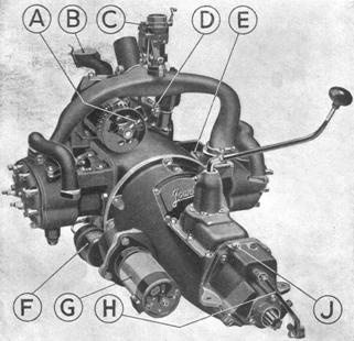
Figure 6.
A. Dynamo Oiler E. Valves (Uncovered)
B. Sump Oil Filler Cap F. AC Pressure Oil Filter
C. Carburettor G. Starter Motor
D. Distributor Shaft Oiler H. Synchroniser Operating Lever
J. Synchroniser Oil Filler Plug
The hydraulic engine mountings require topping up with oil about every 2,000 miles. Remove the round-headed screw from the top of the mounting and fill with engine oil until it overflows, then replace the screw.
GEARBOX
For the gearbox, the recommended oils are either (Patent) Castrol XL or Duckham’s Adcol N.
The combined oil filler and level plug will be found on the off-side of the gearbox when the front floorboards are taken up, and oil should be poured in until the level rises to that of the plug. The gearbox should be examined for oil level every month, and every six months the oil should be drained away, the gearbox flushed out with paraffin and refilled with clean oil. The speedometer drive and the clutch are both lubricated from the gearbox; in the first case, the lubrication is direct, the speedometer drive being built into the rear end of the gearbox.
In the case of the clutch, lubrication is brought about via a drilled first motion shaft which conveys oil to the clutch thrust race and the clutch spigot bearing on the end of the crankshaft (see back cover for details). Any surplus oil is thrown out of the inside of the clutch by oil thrower discs mounted on each side of the clutch friction member. Small holes are drilled in the flywheel to release any surplus oil from the inside of the clutch.
When a gearbox synchroniser is fitted, this component is designed to receive lubricant from the gearbox, but after draining the gearbox and flushing out with paraffin, half a cupful of oil should be poured into the synchroniser housing through the filler plug located on top of the housing. A full description of the synchroniser is given on Page 4.
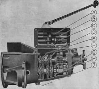
Figure 7.
A. Gear Selector Top And Third F. Third Speed Gears
B. Gear Selector First And Second G. First And Reverse Gears
C. Gear Selector Reverse H. Second Speed Gears
D. Reverse Shifter J. Gearbox Drain Plug
F. Constant-Mesh Gears
BACK AXLE
The filler plug will be found at the top of the differential housing and may be reached by lifting up the steel panel underneath the rear seat cushion. A level plug is mounted below the bevel pinion housing, and both plugs should be removed when topping up with oil which should be poured into the top orifice until it overflows from the level plug hole.
Filling is easier if the oil used is warm and that already in the axle is fairly fluid as after a run. A test for oil level should be made when the oil is fluid under the above conditions, but a short time should be allowed to elapse with the car standing so that the oil can drain off the gears and casing. Examine back axle for oil level every 1,000 miles. The recommended oils are either (Patent) Castrol XL or Duckham’s Adcol N Gear Oil.
The rear hubs are arranged for lubrication by grease-gun. The nipple feeding the hub is immediately accessible when the rear wheel disc is removed. Provision is made in the hub design for the exclusion of grease from the brake drum, and the gun should be applied freely to the nipple at intervals of 5,000 miles.
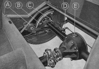
Figure 8.
A. Shock Absorber Oil Filler D. Rear Brake Compensator
B. Brake Adjusting Nut E. Back Axle Oil Filler Plug
C. Brake Pull Rod
A complete repacking with grease is recommended during the annual overhaul. Jack up one side of the car, removing the six nuts from the inner hub flange adjacent to the rear spring, detach the brake rod from the compensating link by withdrawing the pivot pin, and take the whole hub assembly out of the axle. Wipe away old grease and repack with new.
FRONT AXLE AND STEERING
The front hubs run on ball bearings mounted on the stub axle and obtain their lubricant from the hub shell, which is packed with grease. A grease nipple is provided on the hub shell, and the grease-gun should be applied once every 5,000 miles. Give half-a-dozen pushes with the gun against this nipple. Care should be taken when greasing the hubs that too much grease is not forced in under pressure of the gun, or it may find its way into the brake drums. Half-a-dozen pushes, as suggested above, are quite sufficient if done periodically. Swing the hub round during the process to distribute the grease. When washing the car, do not force a strong jet of water on to any of the front axle or steering parts.
The 8-H.P. steering box needs little attention beyond an occasional application of the grease gun to the nipple provided.
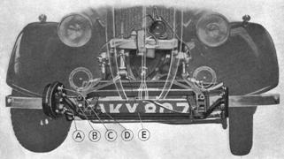
Figure 9.
A. Stub Axle Pin Bottom Greaser D. Front Brake Compensator
B. Stub Axle Pin Top Greaser E. Steering Thrust Ring
C. Brake Adjusting Nut
It is attached to the front cross member by a bracket holding a Silentbloc bush, which absorbs a large amount of road shock and requires no lubrication. To lubricate the steering joints at each end of the track rod and steering coupling rod, remove each front wheel in turn and apply the grease-gun to the nipple at each end of the two rods. This should be done once a month.
On the 10 H.P. four-cylinder car the steering box and column are of Manes-Weller type and lubrication is only necessary at two points. The top bush of the column just beneath the steering wheel should be given a drop or two of oil every now and again, and the steering box itself should be kept full of lubricant. A square-headed plug is conveniently placed at the top of the housing and this should be removed and a good medium oil poured into the orifice until it overflows. Castrol Swanshot Gear Oil is recommended by the makers of the gear as being the best lubricant for the mechanism.
Figure 10.
A. Thrust Washer F. Steering Box Bush
B. Eccentric Bushes G. Steering Ball
C. Locking Collar Bolt H. Gear on Column
D. Silentbloc Bush J. Internal Gear
E. Castle Nut
ADJUSTMENTS
|
W |
herever there is likely to be wear or disarrangement of any component, provision is made to overcome this by adjustment. In an instruction book which is necessarily limited in size, only those adjustments of major importance can be described. If in doubt about any part not dealt with in the book, our Service Department at Idle will be glad to advise.
VALVES — TWIN-CYLINDER
Remove the valve covers by unfastening the four set screws holding the two halves together. Adjust the valves so that there is 6-thousandths of an inch clearance between the tappets and the valve when the engine is cold. Spanners are provided in the tool kit to fit the two hexagon nuts on the end of the valve stem. Hold small or bottom nut, slack off large nut by screwing up ordinary right-hand thread. Turn small nut until required clearance is obtained, hold small nut and lock by large nut.
To ensure that any particular valve is fully closed, adjust one inlet valve, when the inlet on the opposite cylinder is at the top of its lift. Similarly with the exhaust.
The tappet guides, which are a press fit in the crankcase and are located by a yoke fastening, can easily be taken out for examination of tappet heads by removing the yoke fastening and using leverage with a screwdriver between the shoulder on the tappet and the crankcase.
A feature of the valves is the method of lubrication obtained by drilled valve tappets and guides. If the valve guides or tappets are at all disturbed, care should be taken that they are re-assembled in the following manner to ensure that proper lubrication takes place. The inlet tappet guides are marked with a file for the top position and are not interchangeable. The valve guides have a small hole drilled in the collar and this must be placed underneath.
When replacing valve covers, use some oil-tight sealing compound to re-make the joint between the covers themselves and the cylinder.
VALVES — FOUR-CYLINDER
Aluminium valve covers enclose the valve chambers on each pair of cylinders. These can be lifted off after the two bolts holding them have been unscrewed. Adjustment is by hexagon nuts on the end of each valve stem and clearance between the bottom nut and tappet should be set to 6-thousandths of an inch for inlet and 6 for exhaust in exactly the same manner as described for the two-cylinder engine. Before adjusting any particular valve for clearance, make sure that the valve is properly down on its seat. Adjust the valve of one cylinder whilst the similar valve on the opposite cylinder is at the top of its lift. For example, if the nearside front cylinder inlet valve is being attended to, turn the engine until the offside front cylinder inlet valve is lifted to its maximum height. The tappets are housed in a removable casting and the whole of the mechanism for one pair of cylinders can be taken out for inspection very simply. The valve chambers of the four-cylinder engine are open to the crankcase, and lubrication of the valve and tappet mechanism is by splash from the force fed crankshaft.
On all models, the correct adjustment of the valves plays an important part in the power output of the engine, and also considerably affects the slow running. If insufficient clearance is allowed, there is a danger of the valve “riding” and subsequently burning.
If too much clearance is given, noise will result. Adjustment must be made when the engine is cold.
STEERING — TWIN-CYLINDER
The steering column revolves in a steady tube at the bottom end where it enters the steering box. The column is supported in this steady tube by two eccentric bushes, so that when the tube is turned round the action of these eccentric bushes will be to set the gear on the end of the steering column, either further into mesh with the internal gear on the steering box or to bring it out of mesh. When the car is made, the thin part of each eccentric bush is placed underneath. By turning the steady tube in either direction, thereby bringing the thick part of the bush underneath, any slack between the steering pinion on the end of the column and the internal gear on the steering box can be taken up. A glance at Fig. 10 will help you to understand the working of the steering. If, with the front wheels held, play in excess of ¾ in. on the periphery of the steering wheel can be felt, with reference to Fig. 10, adjust as follows : — Slack off locking collar bolt on steering box, grasp steady tube firmly with both hands and turn sufficiently to take up the excess play in the gears. The correct adjustment is reached when there is approximately ¼ in. movement of the periphery of the steering wheel with the road wheels stationary. Care should be taken that the steady tube is not pulled out of the steering box at all.
If the steering box is disassembled for any reason, do not, upon re-assembling, tighten up nut E dead tight. There is a spring washer under this nut which automatically takes up end play due to wear. This spring washer should be nipped up until almost closed. The correct tightness is reached when the steering box turns freely yet is without end play. The steering box is fastened to the frame-side by a tie-rod, the function of which is to check lateral movement permitted by the Silentbloc bush on which the steering is mounted. This tie-rod should be examined occasionally to see that all nuts are dead tight.
STEERING – FOUR-CYLINDER
The steering gear fitted to the Jowett 10 H.P. car is of Marles-Weller type and the mechanism is sturdy and of sound construction, needing but little attention over long periods, so far as adjustment is concerned. The operation of the gear is perfectly simple; a hardened steel cam in which a spiral groove is cut revolves with the steering wheel. Into this groove is inserted a follower with two hemispheres let into each side, their flat faces making contact with the sides of the groove in which they align themselves automatically in every position. The follower is housed in a radius arm which pivots on a shaft revolving in the steering box itself and carrying on its outer extremity a drop arm which operates the steering coupling rod.

Figure 11.
A. Front Hub Greaser P. Brake Operating Plunger
B. Outer Ball Race Q. Front Brake Pull Rod
C. Packing Sleeve R. Near-side Brake Link
D. Inner Ball Race S. Compensator Operating Arm
E. Brake Drum T. Compensator Link Arm
F. Brake Adjuster U. Off-side Brake Link
G. Inner Bearing Locking Ring V. Ball Socket Greaser
H. King Pin Top Bush Greaser W. Outer Half Ball Socket
J. King Pin Bottom Bush Greaser X. Steering Ball
K. Shock Absorber Arm Y. Inner Half Ball Socket
L. Front Spring Z. Ball Socket Spring
M. Front Brake Compensator AA. Steering Coupling Rod
N. Stub Axle King Pin AB. Steering Drag Link Greaser
O. Steering Arm
Adjustments to take up wear are two in number and affect end play of the cam and side play of the follower in the cam groove. Evidence of excessive end play in the cam is given by movement in the steering column up and down in the direction of its centre line. There should be no appreciable movement in this direction and its presence indicates that wear has taken place between the cam and its supporting bearings; adjust as follows. Remove the bottom flange from the steering box disclosing the packing shims between it and the main body of the housing. Separate these shims and take out one at a time, replacing the flange after removal of each shim and tightening up the bolts holding it until end-play disappears. Be careful not to remove too many shims, or excessive tightness between the cam and its bearings, leading to stiff steering, will result. Remake the joint between the flange and housing with jointing compound and refill the steering box with oil (see chapter on lubrication, Page 8).
Side play between the follower and the cam is shown by excessive free rotary movement of the steering wheel before any effect is felt in the steering itself. There should be no free movement of this description, but wear of the hemispheres in the follower through a long period of use may cause this free movement and replacement of the hemispheres is advisable. To do this, first of all jack up the front axle so that freedom of movement of the steering is possible, then drain the steering box of oil. Now take off the side plate on the steering box, withdraw the follower from its bearing in the radius arm by working the arm gently upward and downward until the follower can be grasped and pulled out. Avoid during this operation any sudden movement which might cause the hemispheres to drop out into the bottom of the housing: Now wipe the follower and hemispheres clean of oil, smear the cups with thick grease, replace hemispheres on one side with new ones and press them into position, slightly tilted to give a lead-in effect.
Swing the radius arm to one side and try the follower in the centre of the cam. If no side play can be felt, re-assemble, but if play still persists, replace the other pair of hemispheres with new ones. When re-assembling, proceed as follows : —With the hemispheres fixed in the follower as described above, insert in radius arm when the latter is swung over to either end of the cam, where the track is wider than it is in the centre. Press in the follower with gentle pressure (this is often simplified if an assistant moves the steering wheel slightly to and fro) and replace the side plate, making sure of the joint with a good jointing compound. Refill with oil. The shims between the side plate and the main housing must not be removed since they are not so placed for adjustment purposes.
If for any reason the drop arm on the steering box is removed, it is advisable to mark the arm and its shaft carefully before removal, so that it can be replaced in its exact position. In a case where the drop arm has been removed without previous markings, proceed to re-assemble as follows. Set everything to straight ahead, the front wheels and the steering gear. The front wheels can be gauged with the eye and the steering wheel can be spun from one lock to the other, and half way back again, by counting the number of revolutions. Now set the front wheels over slightly as if the car was turning a wide left-hand corner. Replace the drop arm with everything in this position. It is advisable before tightening up finally to check over the steering to make sure all is correct. With front wheels jacked up, swing steering over to right lock. Now mark carefully the position of the drop arm in relation to its shaft. Detach drop arm from steering box and see if the steering wheel can be moved any further in the same direction. If it can, everything is in order, and the procedure should be repeated for the other lock. If it is found that the above instructions do not apply, movement of the drop arm over one or more serrations to right or left, as the case may be, will remedy any mal-adjustment.
BRAKES
Bendix-Cowdrey brakes, with fully compensated operation, are fitted to 1937 Jowett Cars. Running adjustments are made at the wheels themselves, and normal wear can be taken up periodically by tightening each brake adjuster one notch or “click.” After a number of such adjustments it is advisable to check over the system generally.
To do this, release the hand-brake lever completely and tighten up each shoe adjuster until tight by rotating in a clockwise
direction; then slack back each one six notches.
To make sure that the brakes are clear it is advisable to take the car out on some stretch of road where a run of about half a mile can be made without using the brakes. Stop the car with the engine only and test each drum for undue frictional heat, which will be caused if any brake is rubbing. If any drum is found to be hot, slack off all drums one notch and the trouble should disappear.
If the car has a tendency to pull to one side, it does not necessarily mean that adjustment is incorrect, although this should first be checked. It may possibly be caused by a seized-up connecting link yoke or bearing which, through lack of grease, has become rusted; or by grease on the brake linings. A rusted yoke or bearing in the operating links require freeing and then liberally coating with grease. Brake linings which become greased up cannot be satisfactorily cleaned, and in such cases new replacement shoes should be fitted.
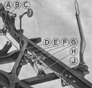
Figure 12.
A. Front Brake Compensator F. Central Brake Compensator
B. Shock Absorber Filler Plug G. Handbrake Link
C. Brake Pedal H. Stop Light Switch
D. Oil Hole for Brake Shaft J. Handbrake Link
E. Footbrake Link
A complete overhaul of the brakes is necessary at intervals of approximately 20,000 miles or annually during the general overhaul. The operating mechanism on each shoe will require taking down, repacking with grease or replacing, and shoes may need renewal. This job is best left in the hands of a Jowett agent or Bendix Service Agent, and is not one which the Jowett owner is recommended to do for himself. Brake shoes should not be re-lined, but service replacement shoes fitted, the old shoes being returned for credit either to these works or Bendix Ltd.
The brake-operating rod yokes and links should be smeared with grease and occasionally given a spray with penetrating oil. The operating rods, should they ever be removed, must not be altered in length in any way, and the compensating links must always work perfectly freely.
Correct adjustment and lubrication will ensure safety, long life and smooth running to your brakes. Safety first! It is more important that you should be able to stop quickly than to go quickly.
CLUTCH
The Jowett clutch is of the single dry-plate type, and rarely needs attention. The friction member is built up of two outside plates of die-pressed brass bonded asbestos, and the centre plate of spring steel cut into vanes like an electric fan, the vanes being flat but staggered to give a spring effect. Resilience of the clutch friction member is thereby attained, and a sweeter action results.
Wear of the clutch plate causing slip can be taken up as follows, references being given on Fig. 13. Slack screw G until there is 1/16 in. play in the toggle lever A before it commences to act. Lock with locking nut F. Repeat this for all three toggle levers. There should always be movement of about 4 in. in the clutch pedal before it commences to act.
Clutch slipping may also be caused by oil on the clutch plates, and can be cured by injecting petrol into the clutch. The presence of such oil is usually brought about by the use of the wrong grade, or too high a level in the gearbox. If the clutch slips after changing up, try closing the throttle for a moment, and then pick up in the ordinary way. If the clutch now holds, it signifies lack of lubrication of the clutch splines. Here again the grade or level of the gearbox lubricant may be at fault, but if not, try the application of a few drops of oil from the oil-can to the thrust race and the splines. Fierceness of the clutch is a fault seldom found, but if it is experienced a cure can be effected by injecting a few drops of oil into the clutch.
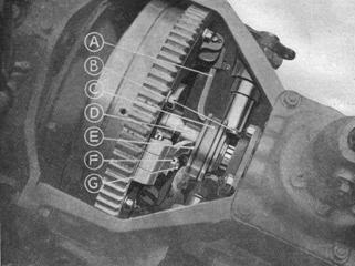
Figure 13.
A. Clutch Toggle Lever D. Clutch Centre
B. Clutch Shaft Toggle Lever E. Clearance Between A and C
C. Clutch Thrust Race F. Clutch Toggle Lever Locking Nut
G. Clutch Toggle Lever Adjusting Screw
BACK AXLE
Adjustments on the back axle are provided for wear between bearings and pinions which affects the meshing of the crown wheel and final bevel drive. Sideways movement of the differential mechanism embodying the crown wheel is allowed for by screwed sleeves locating the differential taper roller bearings, which are permanently locked in position when adjustment is correct. If there is back lash in the cardan shaft with the crown wheel held firm, amounting to more than ⅛-in. movement on the outer radius of the flexible joint, it signifies that adjustment is necessary, and rectification should be carried out as follows.
Drain oil from axle casing and remove back plate. At each side of the differential housing will be seen the bearing caps and the screwed rings (D, G, B, Fig. 14) slotted for location by the locating screw and peg C. These screwed rings bear against the outer race of the taper roller bearings supporting the differential and the one on the nearside has a right-hand thread, whilst that on the offside has a left-hand thread. Remove first the locating screws and pegs, then move the offside screwed ring one slot upward and the nearside ring one slot downward. Test for back lash and if still persistent, move each ring another slot. When the required adjustment has been made, replace the locating pin and screw, also the piece of stout wire through the head of the screw. Re-assemble the back plate on the casing and refill the axle with recommended lubricant.
Movement of the screwed rings one notch is equivalent to movement of the differential 2+ thousandths of an inch. A further adjustment for mesh of crown wheel and bevel pinion is provided at the bevel pinion flange, where shims are interposed between the flange and the bevel pinion housing. This is, however, an assembly adjustment necessary only when fitting a replacement crown wheel and bevel pinion.
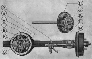
Figure 14.
A. Rear Brake Link Yokes G. Axle Bearing Cap (Near-side)
B. Axle Adjusting Ring (Screwed) H. Brake Shoe
C. Adjusting Ring Locking Screw J. Rear Hub
D. Axle Bearing Cap (Off-side) K. Axle End Nut
E. Crown Wheel L. Brake Adjusting Wheel
F. Differential M. Rear Hub Greaser
BACK AXLE—REPLACEMENT OF BROKEN SHAFT
The Jowett back axle shaft is a very reliable member with a big margin of safety and rarely gives trouble. In the event of shaft breakage, the following procedure should be carried out. Jack up side of car and take off the wheel. Then remove the six bolts from the axle flange close to the spring seat. Disconnect brake shaft at the yoke end by removing the swivel pin. This done, the hub, brake drum and half axle shaft can be withdrawn in complete assembly. If the broken half of the shaft remains in the axle, it will have to be removed, and it will be necessary to extract the oil-sealing washer from the hub end of the axle casing. To remove the broken shaft from the hub assembly, first take off the brake drum, which is held by two countersunk screws, and draw the hub off the shaft. Now remove the two lock nuts on the shaft which locate the end bearing and tap the shaft out of the bearing. Examine this bail bearing very carefully, because if the car has been allowed to run even a short distance with a broken axle shaft, damage to the bearing necessitating its renewal will almost certainly be caused.
To assemble the replacement shaft, insert it through the bearing and locate it tightly with the two locking nuts. Now place hub key in keyway and drive on the hub, tightening it up firmly with the axle end nut. Replace the split pin in the axle end. If the oil-sealing washer has been removed, replace it in the axle casing. The axle shaft may now be assembled to the differential, note the correct location by the brake rod position, and insert the splined end carefully into the balance gear of the differential. Replace the six nuts on the axle flange and tighten up. Reassemble the brake drum and the brake connecting link, charge the hub with the recommended grease according to instructions given under “Back Axle Lubrication”, Page 7. Refix the wheel, and, finally, if the back plate of the differential has been removed, top up the axle with recommended oil, Page 7.
BACK AXLE—REMOVAL OF DIFFERENTIAL
This is only necessary if any failure occurs in the differential gears or the final drive. Jack up the car one side and place a prop beneath the frame, then transfer the jack to the other side. Withdraw each hub and half shaft assembly (see Page 11), drain the axle of oil, and take off the differential rear cover plate. Now remove the locking screws and pins from the adjusting rings and release all pressure on the differential bearings by screwing upward two or three notches the screwed ring on the nearside of the differential. Remove the clamping bolts on the bearing caps and take away both bearing caps and adjusting rings. The differential assembly will now come away. When re-assembling, take care that the adjusting rings are quite free of the bearings, and that they are re-assembled in the same order in which they were found. When the job is finished, adjust the mesh of the spiral bevel drive as instructions, on Page 11.
To remove the bevel pinion from its housing, a special drawing tool is required, and the cardan shaft must be removed from the axle (see Page 13). Remove the end-packing washer and the roller-bearing locating washer from the end of the housing, and with the special tool withdraw the pinion. Shims are fitted between the roller-bearing housing and the flange face of the bevel pinion housing. These are for adjusting endwise depth of bevel pinion in mesh with crown wheel and need only be disturbed when a new pinion and crown wheel are being fitted. Attention to the bevel pinion, as outlined above, is not an operation within the scope of the normal owner-driver, neither is it ever likely to be necessary except in the case of total failure of the final drive gears.
TIMING CHAIN
Every six months the timing chain should be inspected for slack. The inspection plug in the timing case cover should be removed, and the chain tension felt with the finger. The plug has a cruciform depression into which the end of a spanner will fit. At the correct tension, there is a certain amount of elasticity in the chain, due to stretch, but there should be no appreciable amount of slack. If the chain feels slack, the three nuts securing the dynamo should be loosened, and the dynamo pulled over bodily towards the nearside front mudguard, until the required tension is reached, when the nuts should be securely retightened.
On four-cylinder models, there is a special chain tensioner fitted to the dynamo flange, by use of which the chain can be tensioned any desired amount when the three flange nuts are slackened.
IGNITION
A screwdriver with gauge complete is provided in the tool kit for adjusting the contact breaker points in the distributor head. The correct gap when the points are fully opened is 10-12 thou. of an inch. Check up this gap occasionally, and if necessary rectify by moving the contact breaker pivot, which is located by two screws, one at each end, slacking off the screws and adjusting the gap between the points to 10-12 thou. Sparking plug gaps should be checked occasionally. The correct gap is 20 thou. for both twin and four-cylinder engines.
WHEEL ALIGNMENT
The track rod is adjustable in length for front wheel alignment. This should be checked over periodically, and for this purpose a stick can be made of suitable length and used as a gauge. The wheels are correct if parallel, but can be set slightly out of alignment providing that the smallest measurement is found at the front of the wheels. This “toeing in” should never exceed ⅛ in. Never set the wheels to toe out, and always jack up the front axle when making this test. If the wheels are found to be out of alignment, slack off the nut on the locking sleeve on the offside end of the track rod. Uncouple the track rod from the steering arm, and screw up the adjustable end until correct alignment is reached.
GEARBOX SYNCHRONISER
Trouble with the gearbox synchroniser is not likely to be encountered, but if the mechanism ever has to be taken down for adjustment or replacement of any parts, the following procedure should be carried out:
Disconnect the cardan shaft front coupling from the gearbox, and swing the shaft out of the way. Place a jack under the gearbox and screw it up until it just takes the weight of the engine, then unfasten the rear engine mounting bolts which pass through the lugs on each side of the synchroniser housing. Remove the link from the clutch pedal, also the speedometer drive cable; the synchroniser unit complete in its housing can now be tapped off the gearbox rear flange after the nuts securing it have been removed.
The first motion sleeve will remain on the gearbox tail shaft (Fig. 3, Page 4), but the rest of the mechanism will come away with the housing. The operating shaft and fork can now be withdrawn after the end collar has been removed. The fork will bring away with it the inner dog clutch member (J, Fig. 3, Page 4 ).
To take the main body of the synchroniser out of the housing, the cardan shaft joint jaw nut will have to be removed and the jaw drawn off the housing.
Further disassembly is straightforward. If, by chance, the delayed action spring (G, Fig. 3) is broken or removed, care should be taken that it is re-assembled correctly. Looking at the synchroniser from the gearbox end, the spring must be wound round its groove in an anti-clockwise direction. Locate the peg on the thin end Of the spring in the hole provided in the groove, and take great care to see that the ring works quite freely when assembled.
To put back the synchroniser unit, make sure first of all that the inner dog clutch member is properly located. Assemble to it the operating fork and shaft, press it in to position and turn it anti-clockwise, then clockwise, until it drops into place. Now look down the centre and see if the splines locate with the splines on the inner member of the freewheel. If they do, the assembly is correct; if not, withdraw the dog clutch member and try again until the splines do fall in line.
The mechanism can now be placed on the gearbox and the various connections linked up. One last point: do not interfere with the stop bolt which limits the travel of the lever pressing on the operating shaft. The position of this stop is set at the works, and it determines the limit to which the operating shaft may be pushed forward. If the shaft is pushed too far, the mechanism will tend to lock on the reverse dogs.
FRONT HUB
The front hubs run on ball bearings, and to disassemble jack up the car, remove the wheel and brake drum and lever off the grease retaining cap from the hub shell, using a hammer and screwdriver against the lip. Knock out the split pin from the end of the stub axle and take off the castle nut and washer. Make a careful note of the washer assembly so that it can be replaced the correct way round.
With the aid of a hub-drawer and the wheel nuts, draw the hub off the axle. The two ball races, together with a spacing sleeve, will come away with the hub shell. These bearings are a press fit in the hub, and if they have to be removed for replacement, obtain a mandrel ¾-in. in diameter, slip it inside the hub and knock out the outer race, which is the one with the smallest diameter. The inner race is held in position by a screwed sleeve, which is locked by a spring ring. Take off the ring and screw out the sleeve; then with a suitable mandrel tap out the ball race. In between the screwed ring and the stub axle inner face there is a sealing washer for keeping grease out of the brake drum. This may require replacing. When re-assembling the hub, proceed in the reverse order to above, and re-pack with grease before assembling. See Fig. 11, Page 9 for references.
REMOVAL OF GEARBOX
If, for any reason, it is necessary to remove the gearbox, it should be done as follows : — Pull hand-brake hard on, place jack under rear of oil sump and screw it up until it just commences to exert pressure on the sump casting. Take up the front floorboard and remove the centre portion of the body front, then remove the front flexible coupling. Screw off the speedometer drive cable from the gearbox, disconnect the starter cable and remove the bolts holding the gearbox to the engine. The gearbox rear mounting should be removed en bloc with the gearbox. There are three bolts fastening the mounting to the gearbox cross member. The gearbox should now come away easily; replace in the reverse order.
On four-cylinder models where the gearbox is fitted with a synchroniser, the whole assembly should be removed complete. Follow the above instructions, and, in addition, disconnect the clutch pedal link from the synchroniser lever.
The removal of the gearbox lid presents no difficulties on the twin-cylinder model, where the synchroniser is not fitted. On four-cylinder cars, however, difficulty may be encountered, and reverse gear should be engaged, upon which the lid will come away quite easily.
CLEANING OUT OIL SUMP
This operation is necessary after the first 1,000 miles, and every 5,000 afterwards, and should be performed immediately after a run, when the oil is warm and therefore fluid and thoroughly agitated. A receptacle for the waste oil should be placed beneath the drain plug at the rear of the crankcase and the plug removed. The old oil will then drain out, and the crankcase should be repeatedly flushed with a small quantity of clean oil. Flushing is made easier if this oil is warm. Do not use paraffin.
When cleaning the oil sump, attention should be given to the filter, which will be found at the rear of the crankcase on the nearside on twin-cylinder engines and on the offside on four-cylinder engines. This should be removed and thoroughly cleaned with paraffin. Fill the sump with 4½ pints (twin-cylinder), 6 pints (four-cylinder) of either Wakefield’s (Patent) Castrol XL in Summer and CW in Winter, or Duckham’s (Aero) NP3 for both Summer and Winter.
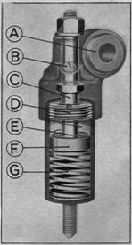
ENGINE SUSPENSION
 Figure
15. (Right)
Figure
15. (Right)
A. Rubber Bush
B. Oil Filler Screw
C. Piston Rod
D. Top Sealing Plug
E. Non-return Valve Spring
F. Piston
G. Bearer Spring
Hydraulic suspension is employed on all models for the front engine mounting. This form of suspension has a big advantage over all other forms in that it absorbs vibrations of both high and low frequency, insulating the engine from the chassis as completely as possible. Only two points need be stressed, firstly, topping with oil; once a month remove the filler screw (Fig. 15), and put a few drops of Patent Castrol XL in each device. Secondly, if for any reason the hydraulic mounting is removed from the car, take great care to keep it upright, also see that when replacing, the washer which fits underneath the near-side mounting on 8-H.P. models, is also assembled. The gearbox is mounted at the rear on rubber blocks, the bolts passing through which should be kept dead tight.
REMOVAL OF CARDAN SHAFT
A special type of cardan shaft is fitted to all models, equipped with Layrub flexible couplings. These couplings rely for their flexibility on rubber spheres, housed in a metal pressing through which pass the bolts to the jaws on the gearbox, cardan shaft and back axle. Do not lubricate this coupling in any way. Removal of the cardan shaft necessitates its disconnection from the gearbox, leaving the flexible coupling on the gearbox jaws. Drop the rear end and draw it out backwards.
CLUTCH PEDAL STOP
A positive stop is provided below the clutch pedal bearing to limit the travel of the pedal. On the twin-cylinder model, this should be set so that the clutch toggle levers do not touch the clutch friction plate when the pedal is fully depressed. On the four-cylinder model, the stop should be set to prevent further clutch pedal movement after the synchroniser operating lever has reached the stop on the synchroniser housing. It is not advisable to interfere with the adjustment of the stop on the synchroniser housing, as this is specially set at the Works.
OVERHAULING
|
U |
nder this heading fall decarbonising, valve grinding, the examination of pistons, rings, cylinder bores, big and little end bearings, and valve and ignition timing. Providing that good oil has been used, we suggest that every 10,000 miles is a suitable period for carrying out the overhaul of the engine. It is, however, safer to be guided by the condition of the engine itself, rather than by any time or mileage limit If an engine is giving consistently of its best even though 15,000 or 20,000 miles have been run since the last Overhaul, it is foolish to tamper with it. Leave well alone is an excellent guide in this respect, because you may be sure that if and when your engine does need attention its power output and general performance will quickly tell you.
DECARBONISING (TWIN-CYLINDER MODEL)
The symptoms showing that decarbonisation is necessary are lack of power and pinking, due to the formation of hard layers of carbon in the cylinder head, which remain incandescent and fire the mixture before the appointed time. To carry out the job on a two-cylinder engine, the inspection plate in the mudguard and the front wheel should be removed, so that easy access is obtained to the cylinder head. Drain engine of water by removing drain plugs from underside of cylinders. Remove six nuts on cylinder head. The head should then pull off the cylinder bolts, using the sparking plug as a handle. If any difficulty is experienced in removing the head, do not use leverage between the faces of the head and the cylinder, as you will certainly damage these faces and ruin the gasket. In case of difficulty, remove the sparking plug and insert a piece of wood tightly in its place (an old plug will serve the same purpose), now tap the wood (or plug) lightly with a hammer till the head is loosened. Remove the head and gasket, and turn the engine until the piston is seen at the top of its stroke level with the valve pocket. Now scrape off the carbon deposit on the piston crown, valves, valve pockets and cylinder head, with the aid of a blunt instrument, such as a screwdriver. The faces of the cylinder head and gasket must be carefully cleaned before the head is replaced to ensure a good joint. Liquid packing may be used to make sure of this joint, but it is not necessary if the faces are clean and the gasket is in good condition. It is wise to have a set of spare gaskets on hand when decarbonising, since old gaskets are easily damaged. Replace gasket and cylinder head and tighten all nuts to finger pressure. Now consider the six nuts as being numbered consecutively around the cylinder, and tighten each half a turn as follows : — 1, 3, 5, 6, 2, 4, until dead tight. Proceed similarly with the other cylinder. Give all the nuts a final turn when the engine is hot.
DECARBONISING (FOUR-CYLINDER MODEL)
Instructions for decarbonising the four-cylinder model are very similar to those for the twin. Here again there is a removable plate in the front mudguard, and this, together with the wheel, should be detached whilst the car is raised as high as possible on the jack. Drain cocks are fitted to the underneath water inlet elbows on each cylinder block. Each cylinder head is held down by ten nuts, and the head should be removed in the same way as recommended for the twin-cylinder engine. On each side of the engine, one piston will be found at the top of its stroke, whilst the other is at the bottom. Decarbonise the valve pockets and the piston crown of one cylinder at a time, turning the crank to bring one piston to the top and stuffing the other cylinder bore with rag to exclude hard carbon particles. When replacing each cylinder head, tighten up the nuts in numerical order, referring to Fig. 16.

Figure 16. 10 h.p. Cylinder Head (Order of Tightening Nuts)
VALVE GRINDING
That valves require attention is usually indicated by lack of compression. Remove the inspection plate in the mudguard and the cylinder head as described under “Decarbonising,” turn the engine until the piston is at the bottom of the cylinder, and stuff the cylinder bore with clean rag to prevent any of the abrasive compound used in the operation from entering the cylinder. Now slack off the locking nut on the valve stem and, with spanners holding both nuts on the valve, screw it out, using a screwdriver on the slotted head. Fine abrasive powder may be used for grinding the seatings of the valves, if not badly pitted, otherwise a coarser abrasive to begin with. Thoroughly wash all traces of compound away with clean paraffin before replacing the valves, and take care to prevent compound reaching the cylinder walls.
On a two-cylinder engine be careful not to confuse the two valves; the exhaust has a rounded head and is of special heat-resisting steel and should never be replaced with an inlet valve, which has a flat head. Inlet and exhaust valves on four-cylinder engines have heads of different diameter, so confusion is impossible.
In the unlikely event of a broken valve spring, proceed as if you were grinding in the valves, take off the broken spring and replace, adjusting clearances as described under Valves, Page 8.
ENGINE OVERHAULING — TWIN-CYLINDER
For a complete overhaul of a twin-cylinder engine, when the removal of the cylinders is necessary for the purpose, of an examination of the pistons, rings, connecting rod big ends, crankshaft big end bearings, etc., after draining the engine of water and removing the cylinder head, the barrel can be drawn off the crankcase in the following way —Place jack under sump, and screw up until it just takes the weight of the engine. Remove from the cylinders the bottom water connection and inlet pipe. In the case of the offside cylinder it is necessary to take away the steering column by removing the thrust washer retaining ring from the top of the steering steady tube (see Fig. 10, Page 8), disconnecting the wiring from the junction box on the floorboards, and drawing out the column as a whole, fastening it up out of the way. Mark the wiring carefully, so that it can be replaced correctly. The silencer pipes should then be removed by slacking off the clip which holds the flexible exhaust pipe to the front end of the silencer. Last of all, the engine suspension bracket from the hydraulic damper to the cylinder should be removed. You have the cylinder now clear for removal.
If the piston rings are bright all round and not stuck in their grooves, do not remove them, only see that the gaps are evenly spaced round the piston, and not opposite one another. When replacing the cylinder thoroughly oil the bore and piston, and gently compress each ring into the cylinder. Adjustment of a big end bearing to take up slack calls for a certain amount of skill, and is not a job which the owner without experience is advised to tackle. There are no shims fitted, and the half bearings, after removal from the engine, must be filed until the correct fit is obtained.
ENGINE OVERHAULING — FOUR-CYLINDER
The dropping of the frameside below the. cylinder has made the removal of the cylinder blocks very simple indeed. First of all drain off water, then after detaching the exhaust pipes from their flanges and the manifold from the cylinder, the induction pipe bolts can be reached and the pipe itself taken off the engine. The carburettor need not be removed from the pipe, but the controls will have to be detached also the thermometer element. Take off the radiator hoses, and, if thought necessary, the steering column can be withdrawn to give easier access to the offside cylinder. The steering column presents very little difficulty, but be careful to mark the wires which run from the steering box to the junction box after removing them from the latter, so that they can be assembled correctly. Remove the drag link from the drop arm, the steering wheel and control tube, uncouple the steering box from the frame and loosen the clip behind the dashboard. The column can now be pulled out from the front of the car, when the offside is up on the jack. Before attending to the cylinder block the front wheel and the mudguard cover plate should be removed. Now the cylinder flange nuts can be unfastened, the sparking plugs taken out, and the cylinder block can be drawn off the engine. Feel the big ends for slack, the piston rings for sticking, little ends for slack; examine valve guides and seats, tappets and tappet guides.
Decarbonise and grind in the valves (see page 14) and replace in reverse order to above. Take care that tappets and valves, if removed from their guides, are replaced in the same order as when assembled at the works.
VALVE AND IGNITION TIMING — TWIN-CYLINDER MODEL
This is only necessary if, by mischance, the driving chain breaks in the timing case. Under ordinary circumstances, it is unnecessary to disturb the timing case at all, except to take up slack in the driving chain as described under “Timing Chain”. Page 12.
In the event of chain breakage, it is necessary to take off the radiator, water connections, induction pipe and timing case cover, when the engine can be retimed as follows : — Set the flywheel on top dead centre position—this is marked on the rim. Now turn to the timing gears. The two teeth which should be opposite one another at top dead centre are marked with a centre punch. Set these so that the marked tooth on the crankshaft wheel is at the top, and the tooth on the camshaft wheel is at the bottom. With the chain removed, move the camshaft wheel slightly either way, and notice on which cylinder the valves move first. Now time the distributor so that the points are just breaking and the contact breaker segment is about to fire the other cylinder. Set up the camshaft and crankshaft wheels to the marked teeth, and replace the driving chain around the three. Fig. 20, Page 16, illustrates this diagrammatically.
Slight adjustment to the distributor can be made by slacking off the clip at the base and moving the distributor body to advance or retard.
Valve timing to the crankshaft when the camshaft wheel has been removed or replaced should be carried out as follows — Set all valves to 12 thousandths clearance with the tappets. To ensure when setting that the particular valve is fully closed, set one inlet valve when the similar valve on the other cylinder is at the top of its lift; similarly with the exhaust valves. With an all-round 12 thousandths clearance, the inlet valve on either cylinder should be on the point of opening when the flywheel is at top dead centre. For the sake of simplicity, set the camshaft so that the inlet on the offside cylinder is opening, then follow out the above instructions for timing the distributor, the contact breaker in which should be pointing towards the nearside cylinder and the points just breaking. The tappet clearances should then be reset to 6 thousandths of an inch for inlet and exhaust, for running conditions. As a check upon the correctness of the timing, works setting is as follows — When the contact breaker points are just breaking, and the segment is firing the nearside cylinder, the top dead centre mark on the flywheel should be at TDC.
VALVE AND IGNITION TIMING — FOUR-CYLINDER MODEL
The re-timing of the valves and ignition of a four-cylinder engine is naturally a little more complicated than a similar job on the twin. The, following instructions, however, if read in conjunction with Figs. 19 and 21, are not difficult to follow; our advice, however, to the inexperienced owner is — leave such work to the experts.
Figure 17. Cylinder Numbering Diagram
Timing chain failure, again a very rare occurrence, is the most likely cause of engine re timing and to do the job it is necessary to have a replacement chain, since only with the chain in position can the engine be retimed. The cylinders are numbered from the front (see Fig. 17). With the chain mounted on the timing wheels proceed as follows : — Set all tappet clearances to 12 thousandths of an inch, adjusting one valve when the similar valve on the opposite cylinder is at the top of its lift. Draw off both vernier coupling peg plates from their counterparts on the camshafts, set flywheel to TDC for cylinders 1 and 2 (TDC 1 & 2) marked on the rim. Turn the camshaft which operates the valves on cylinders 1 and 3 (cam 1 & 3) with a spanner until the inlet valve on cylinder 1 is just about to open. Replace vernier peg plate on cam 1 & 3, and secure it in position with the camshaft nut. Now turn the flywheel one complete revolution and proceed as above with inlet valve on cylinder 2 and cam 2 & 4. Replace vernier peg plate on cam 2 & 4 and tighten nut. AU the valves are now timed to the crankshaft. If the distributor drive has not been disturbed, at TDC 1 & 2 position of the flywheel, valves set as above, the contact breaker points in the distributor should just be opening and the rotating arm should be making contact with the plug lead of cylinder 1.
If ever it is necessary to disturb the distributor, returning, to the camshaft when the valves are correct should be carried out as follows : — Set the flywheel to TDC 1 & 2 when the inlet valve on cylinder 2 is just about to open. Now hold in one hand the complete distributor, with the cover removed but the gear assembled, and place it in a position directly above that which it occupies when assembled, keeping the flat side of the head (the condenser housing) facing the dynamo. Fig. 21 illustrates this procedure. In this position, turn the segment until it points to cylinder 1. Now turn the gear until the points are just about breaking, keeping to the above position as nearly as possible.

Figure 18
Timing Diagram to Flywheel, ‘Twin’ or ‘Four’. The above timing only applies when tappet clearances are set at 0.012”.
Figure 19.
A. Contact Breaker Segment Firing Cylinder 1
B. Contact Breaker Points Just Breaking
C. Camshaft Sprocket 2 & 4 D. Vernier Peg Plate
E. Timing Chain Spring Link for Removal
F. Dynamo Sprocket G. Camshaft Sprocket 1 & 3
H. Cylinder 1 Inlet Valve Just Opening
J. Crankshaft Sprocket
Looking down the shaft hole in the crankcase, the groove for the oil pump drive will be seen; with a screwdriver in the groove turn the drive until the groove approximates as nearly as possible to the position of the tongue on the distributor gear when that is held as described above. Now turn the distributor head and gear clockwise about 1/6th of a turn to compensate for the screw action of the gears when sliding the shaft into place. Drop in the shaft, and by swinging the flywheel to and fro slightly whilst pressing lightly on the distributor head, the whole mechanism will slide into place. Slight adjustment to the timing can be made by slacking off the screw on the plate beneath the distributor head and moving the distributor body advance or retard as required. The timing is correct when the contact breaker points are just breaking and the segment is firing cylinder 1 when the flywheel TDC 1 & 2 mark is at TDC mark on the crankcase. When all adjustments have been completed, set valves to running clearance of 6 thousandths all round.
Figure 20.
A. Contact Breaker Points Just Breaking in Distributor
B. Contact Breaker Segment Firing Near-side Cylinder
C. Dynamo Sprocket D. Camshaft Sprocket
E. Marked Teeth on Crankshaft and Camshaft Sprockets
F. Crankshaft Sprocket
G. Off-side Cylinder Inlet Valve Just Opening
H. Spring Link For Chain Removal
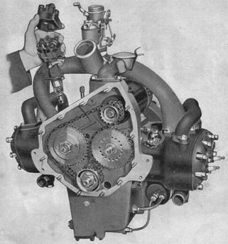
Figure 21.
Assembling of distributor and drive to four cylinder engine after re-timing of camshafts.
GENERAL CARE OF COACHWORK AND FITTINGS
|
N |
othing detracts from the appearance of a oar so much as neglected bodywork and upholstery. Therefore, do not begrudge the occasional half-hour if this feature is of importance.
Cellulose finishes have simplified the cleaning of the car enormously. The body should be washed with clean water, using either a sponge or a hose, tar and grease stains removed with a petrol rag and the car should he polished with a good cellulose polish. Dust can he wiped off dry without scratching the surface; mud, however, should always be washed off.
If the interior of the car is finished in Rexine, or leather, the upholstery can he cleaned with ordinary soap, applied sparingly with a damp cloth. Wipe off the soapy water and dry with a clean cloth. Tar and grease can he removed with a petrol cloth. In the case of moquette interior, a hard brush should be used on the cushions periodically to free them from dust. Dirty patches can he cleaned with the aid of a hard nail brush and a little soap, rubbing from the back to the front. The moquette used on our cars is guaranteed moth-proof.
All fittings, interior and exterior, on the Jowett, are in stainless steel or in chromium plate, and will not tarnish. No polish must be used on the radiator, windscreen fittings, door handles, lamps, inside fittings, etc., simply sponge over with clean water and dry with a soft cloth or wipe with a wash leather and dry.
It is wise when leaving the car standing in the street to make a practice of closing all windows to exclude dust from the interior. When using a hose on the body, do not direct the jet of water on the hubs, nothing ruins a ball-race so quickly as rust, and this is inevitable if water is forced into the hubs under as much as 20 lb. pressure. Provision is made for excluding water from the hubs but a jet under pressure will penetrate where free water cannot reach.
You are recommended in the “Guide to Maintenance”, Page 5. to tighten up the body bolts periodically. These bolts are placed along the frameside, are very accessible, and hold the body to the chassis through a felt pad. There are seven bolts on each side of the car; two at the extreme front of the body underneath the inclined floorboard, one on the floor just in front of the front seat, two opposite the centre door pillar, and one on each side of the rear wheel. Although the examination of these bolts is only a precautionary measure, it is very necessary, as a missing bolt might cause all kinds of body trouble.
A word re bonnet fastenings — to open simply twist and lift the bonnet — to close push downwards with the ball of the hand. A little lubricant on the moving parts is an advantage.
The care of the sliding roof is a very simple matter. So far as the mechanism is concerned, a little grease smeared on the runners down each side of the body is all that is required, plus an occasional inspection of the drain holes to see that they are clear. The runners for the sliding seats should be similarly lubricated. Door locks, hinges and dovetails should be given a drop of oil occasionally.
PUBLICATIONS THAT ARE AVAILABLE
|
T |
he following booklets are issued by ourselves and by manufacturers of component parts of the Jowett. In addition to the Instruction Book, they form a complete set of instructional literature. All are gratis with each new car, and replacements may be had on application.
Jowett Instruction Book. (1s. 6d.)
Spare Parts List. (1/-.)
Zenith Carburettor Handbook. (Free.)
Lucas Handbook on Electrical System. (Free.)
List of Jowett Agents. (Free.)
Shock Absorber Leaflet. (Free.)
AC Fuel Pump Leaflet. (Free.)
S.U. Fuel Pump Leaflet. (Free.)
Electrical Wiring Diagrams. (Free.)
Also our Service Department is at your disposal whenever you need information of any kind.
LIST OF TOOLS
The complete tool kit issued with the car should include: — Tyre pump with connection; Stevenson jack; Wheel Brace; Carriage Key (except on Standard 8-H.P. Saloon); Tyre lever; Oilcan; Starting handle. A tool bag is supplied containing — One 8” adjustable spanner; three double-ended spanners; and one each of the following — Screwdriver; pliers; contact breaker spanner; box key with tommy-bar; brake adjusting spanner; key for gearbox filler plug and valve top nut; sparking plug spanner (on 10-H.P. models only).
THE JOWETT GUARANTEE
|
W |
e give the following guarantee with our vehicles instead of the guarantee implied by statute, or otherwise, as to the quality or fitness of such machines for the purpose required; any such implied guarantee being in all cases excluded. In the case of vehicles which have been used for “hiring out” purposes, no guarantee of any kind is given, or is to be implied.
We guarantee, subject to the conditions mentioned below, that all precautions which are usual and reasonable have been taken by us to secure excellence of materials and workmanship, but this guarantee is to extend and be in force for six months only from the date of purchase, and damages for which we make ourselves responsible under this guarantee are limited to the supply of a new part to replace that which may have proved defective. In the case of a purchase through an agent, the guarantee dates from the day of delivery to the purchaser, providing the vehicle has not been used in the meantime. We undertake, subject to the conditions mentioned below, to make good at any time within six months any defects in these respects. As vehicles are easily liable to derangement by neglect or misuse, this guarantee does not apply to defects caused by wear and tear, misuse, or neglect.
CONDITIONS OF GUARANTEE
If a defective part should be found in our Vehicles it must be sent to us by passenger train, carriage paid, and accompanied by an intimation from the sender that he desires to have it repaired free of charge under our guarantee, and he must also furnish us, at the same time, with the engine number of the Vehicle, the name of the Agent from whom he purchased, and the date of the purchase. Failing compliance with the above, no notice will be taken of anything which may arrive, but such articles will lie here at the risk of the senders; and this guarantee and any implied guarantee shall not be enforceable.
We guarantee only those Vehicles which are bought either direct from us or from one of our duly authorised Agents, and under no other conditions.
We do not guarantee the specialities of other firms, such as tyres, lamps, electrical apparatus, etc., supplied with our Vehicles or otherwise.
THE TERM “AGENT”
is used in a complimentary sense only, and those firms whom we style our Agents are not authorised to advertise, incur any debts, or transact any business whatsoever on our account, other than the sale of goods which they may purchase from us; nor are they authorised to give any warranty or make any representation on our behalf other than those contained in the above guarantee.
JOWETT CARS LIMITED.