TECHNICAL NOTES SERIES
JOWETT JAVELIN – PA, PB, PC, PD & PE
JOWETT JUPITER – SA & SC
The Jowett Javelin and Jupiter engine in cross section.. From The Motor Trader – with thanks.
PART XXVI – MISCELLANEOUS SERVICE TOPICS
(Various Topics In No Particular Order)
The Jowett Car Club of Australia Incorporated is not responsible for any inaccuracies or changes that may occur within this document. Every effort has been made to ensure total accuracy. It is not a Jowett Car Club publication and, therefore, the Club has no control over its contents. These Technical Notes have been compiled by using the latest information available. Updates for these Notes can occur from time to time.
Compiled by Mike Allfrey.
January, 2007
CONTENTS
Topic Discussed Page No.
So, Your Water Pump Is Leaking 3
Technical Article – Javelin Crankshaft 4
Javelin Engine Tuning 5
Club Bulletin No. 3 – Special Tools 5
The Meehanite Crankshaft 6
Replacement Jowett Javelin Crankshaft 7
Electric Fans and Javelins 8
A Break With The Orthodox 11
Jowett Javelin Technical Data 13
Girling Brakes Service Bulletin 16
The Javelin Balance Pipe 24
An Electric Screen Washer 24
Remarks On Javelin Crankcase Breathing 25
Winter Rumblings 26
Remarks On Engine Loading 27
A Technical Résumé 28
Engine Vibration 28
Modified Circular On Propellor Shaft Vibration 29
Modifications To The Water Circulation 30
Varied Cures 31
A Technical Article 32
Jowett Javelin And Jupiter Rear Axle End Float 32
Use Of Vehicle Jacks 33
Jowett Jupiter Door Window Installation 35
The Camshaft Plug (Drawing) 38
Girling Full Hydraulic brakes 39
WARNING!
TECHNICAL DATA IN THIS DOCUMENT SHOULD BE USED WITH DUE CARE.
SO, YOUR WATER PUMP IS LEAKING
Well, this car necessity is fixed quite simply by replacing: the glands and cleaning up the shaft faces which these glands bear against.
The procedure is as follows:
1. Remove the whole water pump and shaft assembly, this is easier with the fan itself removed first.
2. Holding: the shaft cover in a vice, (don’t grip hard on the pump body, you can crack it) remove the pulley off the front – careful, you can crack this also. Undo the securing bolts on the front cover, but don't try to lever this cover off; usually after a few years they are really stuck tight if they had plenty of gasket cement on their previous assembling. You will only break this front flange if you try to force it off. It's easiest to drive it forward by a soft drift against the rear of the fan shaft which will push it out of the pump body. Now the seals will be exposed, well and truly rusted up.
3. Remove the seals and expose the impellor faces. These are probably corroded and rough to the touch. They must be faced across lightly in a lathe, giving them a perfectly smooth face for the seals to butt against. Holden seals are the ones to put in; they're just right for the job!
4. Before pulling the rear of the seal into the body, carefully clean all of the hard oxidised matter from around the inside of the body where the seal sits, giving it as even a seating as possible. Now coat the seat with PPC.49 adhesive to make sure of the seal not letting any water back into the shaft housing.
5. Seal the front one in the same manner into the rear of the front housing. I should also mention the front race being replaced if necessary, but this will probably be OK.
6. Make sure your grease nipple to the bearing, replace if blocked.
7. Put everything back in it's right position with a new gasket cemented onto the cover flange, and if you have done it correctly, it will last for years. I believe my original seals lasted for about 75,000 miles before giving up.
Also, there is a way to take the slack out of the rear bearing of the fan; it’s crude but effective. When the shaft is being faced, the rear of the spindle, which runs in the bronze bush can be lightly cleaned up with a file or lathe tool; then the bush can be drifted out and slotted longitudinally with two blades together in a hacksaw frame. The housing has just enough thickness for a 1/4” BSW hole to be tapped into it, a screw fitted in and screwed against the split bush to close it in slightly against the shaft and reduce greatly this some excessive play here. Don't forget a locknut too on this screw.
Before closing, I almost forgot one thing; if your radiator baffle, that is just below the radiator cap, is loose or right out, you can loose water, as a good efficient water pump can cause water to surge up and pump past the relief valve on the cap and out through the overflow pipe.
As this only happens at normal road speeds of the engine, it is not always obvious, and does not occur when you lift the bonnet to look.
Neil Munro.
From the August 1964 issue of The Javelin.
![]()
ENGINE 0VERHEATING
By J. D. Taylor (Tech Committee)
Although our main summer heat is over, we hope, a word on engine cooling as applied to Javelins may not be too late.
Overheating (boiling), is caused by insufficient heat dissipation by the radiator, or an engine which runs hot beyond the cooling capacity of the radiator, because of mechanical inefficiency. The tendency to boil is considerably increased by hot weather, naturally, especially with a following wind, or high load conditions.
An engine which normally runs hot, (over 75 °C) and which boils with slight provocation, is probably suffering from a blowing head gasket, or a partially blocked radiator core. The cure is of course obvious and imperative in each case. Providing this is not the case, the following points may assist members who are having trouble:
1. Fan belt slipping? The belt can be quite tight and still slip if it runs on the bottom of the pulley grooves. Check for excessive heat marks on pulleys.
2. Have you got a fan on anyway? Very necessary in traffic, but little use on the open road at over 45 MPH.
3. Feel the inside of the top radiator tank for a greasy film which will be right through the water circuit and impairs the heat dissipation of the radiator core. Can be removed with any patent radiator cleaning compound.
4. Wash the engine and radiator with kerosene, using a stiff 1" brush, concentrate on forcing the kerosene into the core. Hose it off with water, and I’ll bet the engine won’t start. Siphon the water from the plug sockets and distributor with a bit of plastic pipe and finish with absorbent cloths.
5. An engine which burns oil suffers from worn rings, and will probably have low compression on most cylinders, due to gas leaking past the pistons. This hot flash, instead of pushing the car along, is lost to the cylinder walls and is carried away by the water with a subsequent increase in it's temperature.
6. Leaking valves also load the water circuit with heat normally used to propel the car.
7. Ignition timing being retarded will have a tendency to cause an engine to run hot. Incidentally a retarded spark will also cause hard starting. Over-advancing the ignition on the other hand will cause the engine to run slightly rough, until the crankshaft breaks at least. The only effective way to set timing on the Javelin is with the aid of a timing light.
8. Lean mixtures take longer to burn than rich, thus the cylinder head is subjected to the flame front for a longer period than normal. In extreme cases the gas may still be burning when the exhaust valve opens, which will protest in due course.
9. Check that the air can flow freely through the radiator, and that it is not obstructed at the vents at the top of mudguards. A sheet of newspaper blown on to the front grille and held there by air pressure can cause some anxiety and has happened. On occasions, I have removed the front grille to improve the air flow to the radiator, but do not recommend this practice in traffic, as the fan belt and pulleys are then exposed and present a pedestrian hazard. Female pedestrians skirts may become entangled which would certainly cause overheating of said female.
10. Check for brakes binding after a run, and bear in mind that the rear brakes can bind if adjusted too close, on the PA and PB model cars, when the car is loaded. The drums will feel hot due to normal use, but excessive heat is quite obvious, I believe soap is a good remedy for burnt fingers.
It is unlikely that anyone of the above troubles would cause overheating alone, but collectively the increased temperature is appreciable.
Happy Hunting.
JD Taylor (Hotspot).
From The Javelin December 1958.
![]()
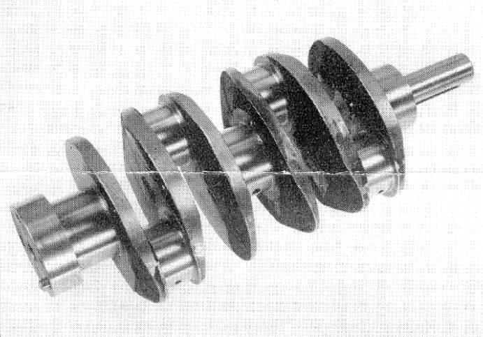
TECHNICAL ARTICLE:
JOWETT JAVELIN CRANKSHAFT AND BEARINGS DEVELOPMENT
In the development stages, the Jowett prototype flat four engines, developed some 45 bhp. It was found that white-metal slipper bearings were satisfactory. Subsequently, the engines, due to improved breathing, were found to be delivering 50 – 52 bhp, and under these conditions bearing failure became prevalent, due the bearing loading causing high oil temperatures.
The first step to overcome this trouble, was to fit 74/24/2 copper-lead-tin bearing slippers, using the un-harden3d crankshaft. There were then no bearing failures, but crankshaft wear increased considerably, and a hardened shaft was introduced, with an improved connecting rod, to lessen distortion on tightening the big-end cap bolts, having a dirt trap hole in the bearing cap. A softer bearing alloy, (69/30/1, copper-lead-tin) was al[o employed.
After its use on competition cars, an oil cooler was incorporated in 1952, but with the cooler in circuit, pressure pulsations occurred at audible frequencies, and the dirt trap holes were deleted, holes in the bottom half of the bearings, were retained however.
When the engine was used. with compression ratios exceeding 8:1, the standard crankshaft failed to last. A mathematical investigation revealed the need for a redesigned unit, incorporating the following features. The fillet radii of all crankshaft journals was increased by 0.100”, and the shaft was lightened by drilling 15/16” holes through the crankpins, the oil feed holes being offset, to avoid these holes. The bearings of course were now narrower to allow for the increased radii, the lock notch in the connecting rod big-ends now being machined 0.040” nearer the centre.
This explains why new bearings sometimes fail to fit the shaft, or bearing cap. A further modification to the connecting-rods and bearings, was the deletion of the dirt trap holes. In the bearings having narrower lock notches.
Here is a list of the modificati0ns, and when they were introduced:
Copper-lead big-end bearings D9 PA 3794
Copper-lead main bearings (Front & centre only) D9 PA 4322
Hardened Crankshaft E0 PB 8002
Improved Connecting rods (serrated cap joint) E0 PB 10506
Sludge release hole in connecting rod caps E1 PC 17402
Fitting of oil cooler January 1952
Hole in connecting rod cap deleted E2 PD 20977
Re-designed Crankshaft (Forged) E2 PD 22190*
Sludge hole in bearing deleted E2 PE 22451
Narrow lock notch E2 PE 22451
* Also on some engines after E2 PD 22161.
The above notes were extracted, and assembled, from the Jowett publication, ‘The Development Of The Jowett Flat Four Engine’, a very interesting booklet.
Bill Fock – Technical Committee.
From The Javelin – July, 1959.
![]()
JAVELIN ENGINE TUNING
The Javelin engine is more prone to be adversely affected by faulty adjustment than the average engine. It is therefore, essential to carefully check the following adjustments when tuning the engine for flat spot, power and petrol consumption:
1. The distributor balance weights must be perfectly free and when the weights are manually opened by turning the rotor, they should return to the fully closed position when released. Do not refit the distributor base plate until this is definitely accomplished.
2. Sparking plugs should he set correctly. Too wide or too small a gap is detrimental. Check all ignition connections.
3. The suction advance and retard unit must work perfectly freely. Any stickiness in this unit will adversely affect performance and cause a flat spot.
4. The valve timing should be checked as per instructions contained in the Maintenance Manual and the carburetion checked for air leaks, pay particular attention to the breather valve fitted to the oil filler pipe and the copper pipe connecting same to the balance pipe, particularly the union on this pipe directly beneath the oil filter.
5. Ignition timing should be set at TDC, using a test lamp, subject of course, to final adjustment on road test. In this respect a setting in advance of TDC is seldom required, but it can sometimes with advantage be as late as 3/8” ATDC. Check on more than one cam lobe. Clean and adjust the distributor contact breaker points to correct gap before setting ignition timing.
Carburettor Adjustments
Throttles – These must be perfectly synchronised. To check this, withdraw both stop screws, close both throttles and set the throttle rod so that there is no tension on the spring couplings.
Choke Controls – For efficient starting from cold, both choke controls must close to the fullest extent and both choke levers must return to the fully ‘off’ position when released. The choke to throttle interconnection must be adjusted so that the engine runs at approximately 1,000 rpm, with the throttle levers clear of the stop screws by about 1/l6”. A further opening of the throttle levers is likely to cause difficulty when starting.
Butterfly Valve – The carburettor butterfly valve, when closed, must seat perfectly in the carburettor body. Any inaccuracy in this fit can upset the final tuning of the carburettors. Check for wear in spindles.
Tuning Slow Running – Run the engine until the thermometer reads 75 °C and tune the slow running air screws; so that the best mixture is obtained at the lowest possible throttle opening, without making the engine 'hunt’. Check the air screw spring for tension (if too slack, screw works loose).
Note: If low octane fuels are used a very slight ‘pinking will be experienced at speeds under 15 mph, or on part throttle, but no pinking should occur on full throttle. Should full throttle pinking be experienced ignition should be retarded slightly.
With high-octane fuels no pinking will be experienced, but this does not mean an ignition setting in advance of TDC can be used with advantage.
Petrol pump – The delivered pressure should not be more than 2 psi. Any excess is likely to increase petrol consumption. If flooding occurs, check floats and needle seats.
Before undertaking any of the above adjustments it is assumed that the air cleaner will have been checked to make certain that it is clean and allowing full air flow, that compressions are good, and the tappets are correctly adjusted. These must only be adjusted when the engine is cold..
The engine temperature must be maintained at 75 °C to obtain the maximum efficiency and miles per gallon.
Carburettor Settings
Javelin Jupiter
Zenith 30 VM-4 Zenith 30 VM
Main Jet – 90 Main Jet – 120
Compensating Jet – 50 Compensating Jet – 65
Fixed Choke – 23 mm Fixed Choke – 27 mm
Slow Running Jet – 50 Slow Running Jet – 45
Author Unknown.
From The Javelin – July, 1965.
![]()
CLUB BULLETIN NUMBER 3 – SPECIAL TOOLS
This issue, is devoted to a list of special tools which may save you many hours of cursing and/or a broken part. Some of them belong to the club; others are privately owned by members but are available for loan in reasonable circumstances. Other precision tools not listed are owned by members and may be available for use by the owner on members engine parts (e.g. micrometers etc.) Contact John Taylor, 232 6331.
1. Engine trolley – a jacking trolley on wheels which makes engine removal simpler.
2. Engine test stand with radiator and exhaust.
3. Perspex tappet covers: to check oil flow rate.
4. Rear main bearing thrust replacement tool: for modifying the rear main to allow use of copper-lead or Alutin bearings.
5. Sleeve removing slide hammer.
6. Valve guide drift: for removing and installing same.
7. Gudgeon pin punch.
8. Piston ring compressor, for fitting new rings without damage.
9. Valve spring compressor:.
10. Clutch aligning shaft: for lining up the friction plate.
11. Gearbox bearing puller: for extracting the mainshaft bearings. These can be very tight and it is difficult work without the puller.
12. Gear change operating shaft reamer: for re-bushing the gearbox housing to make good wear around the vertical operating shaft.
13. Gearbox synchroniser spring compressor essential in overhaul.
14. Gearbox rear oil seal extractor.
15. Driveshaft flange puller: for extracting the keyed flange when removing the engine.
16. Driveshaft flange spanners: two special spanners for loosening the flange nut.
17. Layrub rubber replacement tools, a series of tapers and drifts for overhauling the universal joints.
18. Hub extractor: especially for the rear brake drums, both hydro mechanical and full hydraulic brake systems.
19. Ring nut spanner: for undoing front hub bearing retaining ring (instead using a punch).
20. Front end alignment tool, a calibrated rod for adjusting toe-in.
Tool 18, the hub extractor is currently loaned out and overdue for return. PLEASE RETURN TO ANY Committee MEMBER.
John Taylor – April, 1978.
![]()
THE MEEHANITE CRANKSHAFT
The biography of the Meehanite crankshaft has clouded with the passing years but the following is a fairly accurate resume from some of our long standing members.
The Laystall crankshaft was developed in England in 1955-56, after Jowett Cars Limited closed and replaced the original square webbed shaft which broke adjacent to the webs. The Laystall was in very short supply in Australia until the 1960's as well as being rather expensive at around £100 (i.e. $200). To overcome this shortage and high cost, the South Australian Crankshaft Replacement Company and the Jowett Car Club of Australia each decided to produce a crankshaft with similar design characteristics to the Laystall.
The J.C.C.A. got to the pattern stage in the early 1960s but by this time the South Australian professionals had the Meehanite type GS completed and on the market.
The number of shafts produced was very low, possibly in the order of fifty or so. The shaft was quite successful, its low price and general availability enabled many Javelins and Jupiters to be kept on the road until the Laystall became more plentiful. The low price and availability factors of the Meehanite shaft forced a more realistic and competitive pricing of the Laystall.
To the Club’s knowledge only one Meehanite crankshaft ever broke and that was after a high mileage. Occasionally the club resurrects a Javelin and find one of these crankshafts fitted.
NOTE: The Meehanite crankshaft does break, quite easily in fact. One that was removed from an engine was crack tested and found to have four cracks in it. This was a standard size shaft and the bearing journals were in very good condition. There were no radii at the journal fillets, nor at the nose extension. This crankshaft broke into three pieces after dropping from knee height onto concrete floor. It was just as well that it was not installed ‘as was’ in an engine.
Author not known.
Comment by Mike Allfrey.
![]()
REPLACEMENT JOWETT JAVELIN CRANKSHAFTS
A Meehanite ‘type G.S.’ ductile iron casting. Heat treated to give maximum wear resistance and yet allow flexibility to increase fatigue resistance.
Designed for use in white metal bearing slippers.
Physical properties:
Tensile strength 80,000 psi.
Elongation 3 to 5 %.
The webs have been redesigned to increase the strength, by an additional width of 1 t inches in the form of an ellipse. Unnecessary metal has been removed from the webs at the bearing flanges so that the final weight is close to that of the original shaft. All machined surfaces are ground to standard sizes and dimensions are maintained consistent with the original by virtue of accurate tooling.
The fully machined casting is dynamically balanced at 4,000 r.p.m. Regrinds can be carried out when required to suit the five standard undersize bearing slippers.
The technique and material are the most modern in use for the manufacture of cast crankshafts.
This crankshaft has been introduced after exhaustive tests on the bench and has now been proven in service on the road by many satisfied Jowett Jupiter and Javelin owners.
Manufactured by:
Crankshaft Replacement Company
17 Eversley Avenue, Enfield, S.A.
NOTE: The Meehanite crankshaft does break, quite easily in fact. One that was removed from an engine was crack tested and found to have four cracks in it. This was a standard size shaft and the bearing journals were in very good condition. There were no radii at the journal fillets, nor at the nose extension. This crankshaft broke into three pieces after dropping from knee height onto concrete floor. It was just as well that it was not installed ‘as was’ in an engine.
Text and image taken from a brochure.
Note by Mike Allfrey.
![]()
ELECTRIC FANS AND JAVELINS
As everyone who runs a Javelin is aware, the engine temperature tends to be somewhat. Erratic –in the summer they run too hot, in the winter they run too cold, and take too long to warm up.
CURE: Take the. fan off in winter – then when you get stuck in traffic she gets too warm! I had these problems too and thought perhaps the electric fan as fitted to HZ Holden Kingswood with the air conditioning could solve the problems.
The fan comes in a kit complete with brackets, relay, nuts, bolts and an in-line fuse holder. I had a few problems getting the beastie to fit, but have overcome most – the fan is most successful but during the very hot weather I put the normal fan back on the front.
Of course, another problem may be encountered later, in that the fan draws nearly 15 amps and the poor old generator has a struggle keeping up (perhaps I could fit, an alternator and not tell the purists.
I have set. out below the procedure for fitting the fan together with a few sketches to assist anyone who wished to fit the fan. The kit, by the way, is not made by Holden but is available under the Part Number DCP 2, and costs around $50.00.
Procedure
1. Remove Radiator:
2. Assemble fan as per makers instructions, except it will be necessary to fit the fan disc the opposite way to the instructions. The fan is more efficient due to the pitch of the blades.
3. Place radiator face down and place fan assembly on radiator with top of plastic fan just clearing the temperature sensor fitting. The brackets should just touch the frame of the radiator, the top set, of holes should be about 3½” down from the bottom of the header tank and the lower set a further 4” down.
4. The easiest method I found for fixing these brackets to the radiator frame was to use either the slip-on spring nuts or make up nut plates as illustrated – this facilitates easy fitting and removal.
5. When the fan is fitted, it will completely clear the choke bracket as it stands about 1” from the radiator face.
It may now be necessary to 'adjust' with a hammer thee point where the two parts of the firewall join together and form a 'protruding' lip, if this is hammered forwards and downwards and the wiring harness tied back out of the way.
6. The radiator and fan should just drop back into place OK.
Electrical
7. When wiring the relay and fan, adjust the polarity so that the fan runs anti-clockwise looking from ,the front of the car (see diagram).
8. The next problem is the heater. On the deluxe version – the connection pipes will foul the fan and brackets unless modified.
9. Remove heater from the car, cut the water pipes off just below the ridges. Clean and tin the pipes and fit ½” Yorkshire fitting right-angle bends and about 3” copper pipe and solder together. This allows the water hoses to come in from the passenger side of the car.
10. You \\'ill also need to enlarge the hole in the firewall to take the bends through.
11. As to the switching of the relay for the fan the ‘in radiator’ type as fitted to Holdens is not very suitable as it needs to be at boiling point to actuate and, of course it would mean another hole in the radiator, or some sort of double adaptor in the temperature sensor hole.
12. There are a number of simple electronic circuits available, enclosed is one that may work with minor modifications. Most use a thermistor, disc type, which can be glued (epoxy resin) to any convenient part of the radiator header tank to sense the temperature.
The electronic system has the advantage of adjustment for cut-in temperature, which of course the fixed ‘in radiator’ type do no t.
Happy Motoring!
Written by Chris Grogan.
Diagrams
Note: The four diagrams reproduced here were scanned from very faint originals in the club’s library file.
Figure 1. General layout of electric fan installation.
Figure 2. Showing fastener alternatives.
Figure 3. Layout of heater modifications.
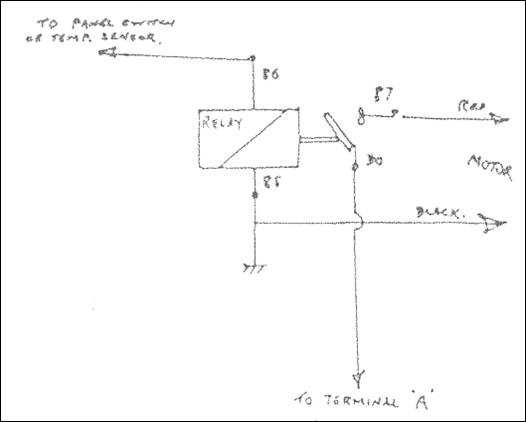
Figure 4. Electrical circuit diagram.
![]()
A BREAK WITH THE ORTHODOX – THE JOWETT
The Flat Four – Crankcase Assembly – Connecting Rods and Pistons – Cylinder Heads and Valve Gear – The Lubrication System.
The Flat Four
In view of its complete breakaway from the conventional in regard to its cylinder layout, it is not surprising to find that the Jowett flat-four power unit incorporates many constructional features which at once stamp it as a thoroughbred. The two versions – Javelin and Jupiter – both follow the same basic design, and in fact the latter engine (used in the open car) is to all intents and purposes a specially tuned version of the more normal unit which powers the saloon.
Figure 1. Performance graph for the Jowett Javelin engine.
The four cylinders have a bore and stroke of 72.5 by 90 mm, giving a swept volume of 1,486 cc. The Javelin produces 52 bhp at 4,100 rpm on a compression ratio 7.2 : 1, while the Jupiter develops 62.5 b.h.p. at 4,500 r p.m. with 7.6.: 1 compression ratio. Maximum torque in the latter case, given at 3,000 rpm, is 84 lb.ft., corresponding to BMEP of 131 psi.
The engine is illustrated on Page 12.
The Case Assembly
The necessity of having two cylinder blocks disposed one on either side of the 'crankcase has not occasioned an excessive number of joint faces. The construction makes use of a single light alloy casting for crankcase and cylinder blocks, split vertically on the centre-line of the camshaft. Wet cylinder liners are inserted in the alloy blocks, being a push-fit therein and having joint rings under the lower flanges. The liners stand proud of the cylinder head gasket surfaces before the cylinder heads bolt down, and are thus securely held after final assembly.
The EN 12 steel crankshaft runs in three thin-wall bearings located by dowels in the split crankcase halves. The rear bearing takes the crankshaft end-thrust on flanges, and has a white-metal lining. The other: two bearings, are copper-lead lined.
The flywheel is mounted on a flange and retained by four setscrews and a dowel. A lipped oil-seal is provided in the clutch housing wall, with its lip towards the crankcase. The shaft is counter balanced, the main bearing journals having a diameter of 2.250” and the big-ends 2.000”. On the front end of the shaft are mounted the oil pump drive skew gear, timing chain pinion, and fan pulley, in that order. A single Woodruff key secures all three items, which are retained by the starting-handle dog screwed into the front of the shaft and locked by a tab washer. The oil-retaining device is formed by he pulley hub running in a lipped seal fitted in the timing cover.
Connecting Rods and Pistons
The steel connecting rods are split, diagonally at the big ends and have serrated joint faces, the angle of the split being 47 degrees to a line along the rod axis. The big-end bearings are of the thin-wall white-metal lined steel-backed type, the caps being retained by two 3/8” diameter bolts. The small-end bush is lead-bronze lined, and lubricated by splash. The split-skirt pistons are aluminium silicon die castings, fitted with two compression and one scraper ring, all above the gudgeon pin. The top ring is chromium plated. The 0.750” diameter gudgeon pin is fully floating in both piston bosses and small-end bush, and is retained by circlips. The pistons can be withdrawn from the top, as the big-ends will pass through the cylinder bores.
The Cylinder Heads and Valve Gear
Each cylinder head incorporates two combustion chambers, and is an iron casting. The combustion' chambers are of bath-tub formation, the valves, being slightly inclined and giving a slightly greater depth of chamber where the sparking plugs are located, and a ‘squish’ area opposite these, The four valves (for two cylinders) are arranged in a single row and are not interchangeable. Inlet valves are of silicon chrome steel, with head diameter of 1.437”, while the exhaust valves, of Austenitic steel, have a head diameter of 1.031”. The seat angles are respectively 30 and 45 degrees, the lift in each case being 0.315”. Duplex valve springs are fitted, with split-cone cotter fixing.
The camshaft is driven-by a Renold 0.375”.pitch duplex roller chain running on 21 and 42 tooth wheels. The short-centre drive has no tensioning arrangement. The camshaft runs in three 1.500” diameter bearings direct in the crankcase. Its end-float is controlled by a spring-loaded plunger bearing on a thrust pad in the timing-case.
The tappets are of the barrel type, sliding directly in the crankcase, and having a special oil supply from the pressure side of the pump into the tappet bores. The tubular pushrods are 5/I6” diameter, and their adjustment is at the top, at the rocker in the normal manner.
The rockers are bushed, and carried on a tubular shaft supported by two pillars. They are located by spacing springs which also aid noise reduction. The valve timing is as follows:
Inlet opens 12 deg. before TDC; closes 53 deg. after BDC.
Exhaust opens 50 deg. before BDC; closes 15 deg. after TDC.
Overlap 27 degrees.
Each cylinder head has a siamesed inlet port feeding the two valves, and two separate exhaust ports. The inlet ports on each head are connected by a balance pipe, a separate carburettor being, of course, fitted to each port, in a position giving an admirable 'drop-in’ feed. The carburettors are Zenith type 30 VM-5 for the Javelin, and 30 VIG-5 for the Jupiter.
The Lubrication System
An oil pump of the usual gear type is driven from the crankshaft at half engine speed by skew gearing. An extension from the pump shaft also drives the ignition distributor.
The pump draws oil through a gauze strainer at the bottom of the 9 pint sump, via a large diameter suction pipe. The pump delivery passes to oil-ways which lead to a full flow filter of Vokes type mounted externally. The Jupiter engine has, in addition, an oil cooler of 1 pint capacity bracket mounted to the engine front and connected by external flexible piping in series with the filter and oil galleries.
The pressure supply from the filter (or cooler) passes to galleries formed in each crankcase half, and lubricating the skew gears, timing chain, tappets, main bearings and camshaft bearings by suitable oil ways. The overhead rocker gear is fed by leads from each gallery incorporated in the cylinder head studs. The crankshaft is drilled for big-end lubrication in the normal manner.
Pressure relief in case of the filter element becoming choked is provided by spring-loading the element itself inside its housing. The pump by-pass relief valve is contained in the pump cover, and is non-adjustable, being set at about 70 lb. per sq. in.
From The Motor Trader – Competition Engines.
LINE DRAWINGS
Figure 2. Sectional views of the Jowett Javelin engine.
![]()
JOWETT JAVELIN – TECHNICAL DATA
Engine
Dimensions: Bore 72.5 mm (2.855”); Stroke 90 mm (3.545”); Capacity 1,486 cc (90.9 ci); Stroke/Bore Ratio 1.24 : 1; Compression Ratio 7.2 : 1; Firing Order 1, 4, 2, 3;. Connecting Rod/Crank Ratio 3.4 : 1; Piston Area 6.4 sq. inches; Piston Speed at 1,000 rpm = 590 ft./minute.
Crankshaft
Four throw with 3 main bearings. Material EN 8 steel. Diameter of mains 2.250”. Length of front, centre and rear bearing 1.1250”, 1.250”, 1.375”. Diameter of crankpin 2.000”. Length of big end bearing 1.000”. Thrust taken on rear main bearing. All bearings steel backed white metal lined (0.072” thick, 0.015 white metal lining).
Flywheel
Special Iron Casting. Shrunk-on Starter Ring Gear in 0.4 % carbon steel.
Connecting Rod
Forged in EN 8 steel. Split at 47°, 5/16” diameter bolts. Small end bearing steel back, lead bronze lined.
Piston
Aluminium Silicon Alloy Die Casting. 2 Compression rings 3/32” wide, 0.133” and 0.123” thick. Gudgeon Pin 13/16” diameter; Floating in Piston and Rod. 1 Grooved and slotted oil scraper ring.
Timing Chain
0.3750” pitch Duplex 56 links. Crankshaft Sprocket 21 teeth 0.6” Carbon Steel. Camshaft Sprocket 42 teeth Cast Iron.
Camshaft
‘Monikrom' Cast Iron. 3 Bearings 1.500” diameter.
Cylinder Block
Die Cast in DTD 133B Aluminium Alloy.
Cylinder Head
Cast Iron. Inlet Port diameter 1.250”.
Valves
Inlet Valve Head diameter 1.4375”. 30° Seat. Stem diameter 0.3125”. Throat diameter 1.250”. Material Silicon Chrome Steel. Valve Lift 0.315”.
Exhaust Valve Head diameter 1219”. 45° Seat. Stem diameter 0.3125”. Throat diameter 1.094”. Material XB Austenitic Steel. Valve Lift 0.315”.
Valve Timing – Inlet opens 12° BTDC. Inlet closes 53° ABDC. Exhaust opens 50° BBDC. Exhaust closes 15° ATDC.
Note: BTDC = Before Top Dead Centre. ATDC = After Top Dead Centre.
BBDC = Before Bottom Dead Centre. ABDC = After Bottom Dead Centre.
Valve Spring Loads. Closed: Outer Spring 45.4 lbs. Inner Spring 35 lbs. Total 80.4 lbs. Open: Outer Spring 71 lbs. Inner Spring 58 lbs. Total 129 Lbs. Valve Rocker Ratio 1.5 : 1. Push Rod 5/16” diameter x 15 swg Tube. Lockheed Hydraulic Tappets 0.8125” diameter.
Oil Pump
Driven by Skew Gear from Crankshaft. ½ Crankshaft Speed. Capacity 3 gals. per minute at 1,000 rpm of pump at 72 °C inlet temp. Pressure release valve set at 50 lbs. per sq. in. Oil Pressure Switch breaks contact at 8 Lbs per sq. inch. Full flow filter, blow off spring set at 15 lbs. sq. inch.
Oil Sump
Capacity 9 pints, A ¼” on dipstick equals 1 pint..
Water Pump
Water pump is driven at Engine Speed by Vee Belt 21/32” Wide (B-Section). 44” circumferential length. Pump capacity 3.8 gals. per min. at 1,000 rpm. Thermostat opens at 75 °C with 1/16” diameter leak holes.
Carburettors
Twin Zenith 30 VM-5, Fixed choke 23 mm.. 90 Main jet. 50 Compensating jet, 50 Slow Running jet. 170 Progression jet with 200 Outlet hole in barrel. No. 2 Cast Capacity well, 2.6 screw over Capacity Well, 1.5 Needle Seat, 1.2 Compensator Vent and deep slow running feed in bowl. Long Taper .Air Screw. Balance pipe between Induction Ports 7/16” internal diameter.
Fuel Pump
AC. Diaphragm 'U’ type. Static Pressure (no delivery) 1½ to 2½ Lbs. per sq. in. Lift 0.118”.
Distributor
Lucas DKY H4A. Ignition set at ½” after top dead centre on flywheel. Advance Range 18° – 22° on crankshaft.
Sparking Plugs
Champion L10. (Superseded by L87YC). Gap set at 0.020”.– 0.025”.
Dynamo
Lucas C45 x V.12 Volt. Maximum output 20 amps at 1,600 rpm. Driven at 1.625 times engine speed. Dynamo speed at 20 mph. road speed 2,100 rpm.
Starter Motor
Lucas M.35G Anticlockwise rotation. Pinion 9 teeth on 10 teeth Blank 10/12 DP. Solenoid Switch. Ring Gear 111 teeth. Ratio 12 : 3.
Performance
12.5 hp at 1,000 rpm; 28 hp at 2,000 rpm; 42 hp at 3,000 rpm; 51 hp at 4,000 rpm; 52.5 hp (maximum) at 4,500 rpm’ Maximum Torque 76 lb.ft. at 2,600 rpm. Maximum. BMEP 125 lbs/sq. inch at 2,600 rpm. BMEP at 4,500 rpm 103 lbs per square inch. Minimum Fuel Consumption 0.555 pint per horsepower hour. BHP per litre 35.2. BHP per square inch Piston .Area 2.05. Piston Speed at Maximum hp 2,660 ft. per minute.
Clutch
Borg and Beck 7¼” AG, Single Dry Plate. Lining Dimensions 7¼”.OD, 5” ID, 1/8” thick, Pressure springs – 3 yellow, 3 maroon. Centre Plate Cushion Springs.3 blue drive, 3 green over-run. Ball Type throwout bearing SKF.400869. Throwout load 180 lbs.
Gearbox
Four Speed forward and one reverse. Constant load synchromesh on 2nd, 3rd and top speeds. .Aluminium Alloy DTD.428 die cast case and cover. Layshaft centre distance 2.600”. Ratios: Top 1:1, 3rd 1.5:1, 2nd 2.38:1, Reverse 3.38:1, 1st 3.88:1.
Gears:
Gear Teeth (Main Shaft) Teeth (Layshaft) Tooth Profile
Constant Mesh Gears 18 34 30° Helical 10 CDP
3rd Speed Gears 23 29 30° Helical 10 CDP
2nd Speed Gears 29 23 30° Helical 10 CDP
1st Speed Gears 35 17 Straight 10 CDP
All teeth 5/8” wide. Machine cut and lapped or burnished after hardening. All gears in EN.59 Steel. Mainshaft 1.250” diameter. Splined EN. 36 Steel. Synchromesh cones 22.250” diameter x 15° Included Angle. Steel on Steel. Speedometer Drive Gear Ratio 8/20 24 NDP.
Propeller Shaft
Divided shaft 2” diameter with 3 Layrub Type 55 x 1.125” joints.
Rear Axle
Salisbury Type Hypoid Bevel. Pinion 8 Teeth. Crown Wheel 39 Teeth. Diameter 7.25”.Hypoid Offset 1.250”. Ratio 4.875:1. Pinion Bearing Front Timken 02474-02420; Pinion Bearing Rear Timken 3188-3120; Crown Wheel Bearings Timken 14138-14283; Wheel Hub Bearing Timken 14123T-14276. Gear Case in malleable cast iron. Tubes 2.250” diameter. Drive Shaft maximum diameter 1.250”.
Front Suspension
Unequal Arm Transverse Link Type. Length Top Link 7.75”. Length Bottom Link 14.94”. King Pin Inclination 10° King Pin Offset 0.75”. Total Wheel Movement 6.375”. Normal Load to Rebound 1.875”. Normal Load to Bump 4.50”. Normal Wheel Camber 0°. Camber at Rebound 1 – ½° Negative. Camber at Bump 1 – ½° Negative. Caster Angle 0°. Torsion Bar Spring. 0.880” diameter, 36” Effective length 36.25”. Torsion Bar Material Silicone-Manganese Spring Steel. Normal Load on Spring .Arm 672 lbs. Stress in Torsion Bar at this load 33.5 tons per square inch. Stress at Full Bump 55.9 tons per square inch. Wheel Deflection at Normal Load 7”. Spring Periodicity at Normal Load 71 cycles per min.
Rear Suspension
Spring Arm Length 13.625”.. Size of Torsion Bar as for Front Suspension. Total Wheel Movement 7.25”. Normal Load to Re bound 3”. Normal Load to Bump 4.25”. Normal Load on Spring Arm 712 Lbs. Stress in Torsion Bar at this load 32.8 tons per square inch. Stress in Torsion Bar at Full Bump 55.5 tons per square inch. Wheel Deflection at Normal Load 6.5”. Spring Periodicity at Noma1 load 73 cycles per minute.
Shock Absorbers
Woodhead Monroe Type 1” diameter. Front – Closed Length 8”, Extended length 11.5”. Rear – Closed Length 11.75”, Extended Length 19”.
Steering Gear
Internal Gear and Pinion Type with 3 piece Track Rod. Number of Pinion Teeth 6. Outside diameter 0.918”. 9.9345 DP 20° PA. 15° Helix A. Material EN36 Nickel Chrome Steel. Gear Teeth – 72 on Complete Ring. Material EN. 32A. CHM. Steel. Steering Gear Ratio 12:1.
Brakes
Girl1ng Hydro-mechanical. Front Brakes 9” diameter x 11.125” wide. Hydrastatic Trailing Shoe. 1” diameter Wheel Cylinder. Linings ¼” Thick x 8” Long. Rear Brakes 9” diameter x 1.25” wide 9° Wedge Angle. Linings ¼” Thick x 8” Long. Total Lining Area 88 square inches. Lining Area per ton of Normal Car Weight 91 square inches.
Master Cylinder 0.875” diameter T Type. Pedal. Ratio 3.8:1. Braking Ratio at Tyre Radius 56.5 per cent, Front; 43.5 per cent, Rear.
Wheels and Tyres
Steel Disc Wheels 3.00 x 16 Rims. 1.375” Inset. 5 Studs 3/8” diameter on 7.375” Pitch Circle Diameter. Tyres – Goodyear 5.25 x 16.
General Dimensions
Wheelbase 102”. Front Track 51”. Rear Track 49” Overall Length 168”. Front Overhang 26½”. Rear Overhang 39½”. Maximum Width 61”. Height – Unladen 62½”. Height – Laden 61”. Front Overhang Angle 27°. Rear Overhang Angle 18°. Ground Clearance under Rear Axle 8½”. Ground Clearance under Sump (laden) 7½”. Ground Clearance under Frame (laden) 9”.
Front Seat Width (Elbow Height) 51”. Rear Seat Width (Elbow Height) 48½” in. Front Seat Adjustment 4¾”. Height – Front Seat to Roof 35½”. Height – Rear Seat to Roof 34”. Height – Floor to Roof 47”. Luggage Trunk Capacity – 9¾ cubic feet. Turning Circle – Left hand Lock 33’. Right hand Lock 34’.
Weights
Shipping Weight (less Radio): 2,168 Lbs. Front Axle 1.187 lbs. (54.8%) Rear Axle 981 Lbs (45.2%).
Kerb Weight: 2,258 Lbs. Front Axle 1,215 lbs. (54%) Rear Axle 1,043 Lbs (46%).
Laden Weight – (4 x 190 lb. Passengers; 150 Lbs. Luggage) 3,168 lbs Front Axle – 1,531 lbs (48.4%); Rear Axle – 1,637 lbs (51.6%).
Performance
Weight of' Car (dry) per cc of. Engine Capacity 1.45 lbs. Weight of Car per BHP of' Engine 41.3 Lbs. Engine rpm per 10 mph 645 rpm. Engine Piston Speed per 10 mph 380 ft per minute. Litres per ton-mile (dry weight) 3,000. Tractive Effort in lbs. per ton (dry weight) – Top Gear 364; 3rd Gear 545; 2nd Gear 866; 1st Gear 1,410. Tractive Effort in lbs per ton (laden weight – Top Gear 250; 3rd Gear 375; 2nd Gear 595; 1st Gear 970.
From Old Typed Sheets.
![]()
Volume 3. Bulletin Number: 124 May, 1950
INSTRUCTIONS FOR THE MAINTENANCE AND OVERHAUL
of
GIRLING HYDRO-MECHANICAL BRAKES
as fitted to the
JOWETT JAVELIN (1948 – 1950)
Description
The "brakes fitted are Girling Hydro-Mechanical. This is a system by which the front brakes are hydraulically actuated and the rear brakes mechanically operated. The Master Cylinder is located in a direct line in such a way that all pedal effort is effectively used and the failure of either front or rear brakes does not put the pedal out of action but leaves one pair of brakes in operation, which enables the driver to make a safe stop.
Front Brakes
These are 9" X 1' Girling Hydraulic Semi Hydrastatic. The shoes are operated by a hydraulic cylinder of simple construction consisting of two pistons on which the brake shoes locate, separated by a light compression spring and two pressure seals. A bleeder valve is incorporated on the top of each cylinder, a rubber cover being fitted to exclude dust, etc. Rubber covers are also fitted over the ends of the cylinder for the same purpose The shoes are anchored at the bottom of the brake back-plate on a pivot, and located on the hydraulic cylinder at the top of the brake back-plate, being held in position by one shoe return spring, at the pivot end and one spring from the leading shoe only to the peg on the backing plate. The trailing shoe has no top shoe return spring, the brake being designed for this :shoe to be in slight frictional contact with the drum.
Adjustment is effected by jacking each wheel in turn, spinning the wheel, partly rotating the hexagon Adjustment Bolt which is to be found on one side of the brake cylinder, until the brake shoe comes in contact with the brake drum, then slackening back until the wheel rotates freely and without drag.
The Adjustment Bolts operate snail-type cams, bearing against the shoes. They are frictionally held and require no locking device, and can easily be rotated with a spanner into the desired position.
Rear Brakes
The rear brakes are 9" X 1" Girling Non-Servo. The shoes are mechanically operated by the expander unit, consisting of a hardened steel plunger, which is actuated by the brake draw link causing the two tappets to move outwards. Hardened steel rollers are interposed between the tappets and plunger to reduce friction to a minimum. The tappets engage directly with the brake shoes. The whole expander mechanism is enclosed in a diecast housing which contains a supply of lubricant. This housing is slidably attached to the back-plate by studs and double spring washers which provide a slight frictional contact. The housing is free to float to a certain extent, the Simmons Nuts on spring washers being one turn slack. In view of this it will be seen that the shoes are self-centring
Adjustment for lining wear is made at the brake shoe adjuster. This consists of a hardened steel wedge, the spindle of which is screwed with a fine thread and is carried in a steel housing which is spigotted and bolted firmly to the back-plate.
On the outside of the wedge spindles are machined flats which enable a spanner to be used and on it's inner face four flats of a predetermined depth are cut. The wedge engages two links, also with bearing in the housing which have inclined faces. On the outer end of these links grooves are formed in which the shoes locates. For adjustment, the rotation of the wedge in a clockwise direction causes it to move inwards forcing the links apart and expanding the fulcrum ends of the brake shoes. The adjuster should be tightened up until a resistance is felt and then slackened back two clicks.
Master Cylinder
The Master Cylinder is connected to the pedal by a slotted jaw. There should be a minimum of 1" lost motion on foot pedal before operating the plunger. When pressure is applied to the pedal, the cylinder is pulled forward. This causes the plunger in the Master Cylinder to displace the brake fluid and operate the front brakes, the rear brakes being operated at the same time by the rear brake pull rod which is screwed into the rear end of the cylinder body. The pull is transmitted to rear brakes via rod and cable to compensator, to which are connected the transverse rods connecting to operating links on the brake assemblies.
In the event of failure of the rear brakes, due to broken or damaged rod, the slip link contacts the stop on the chassis thus arresting any further forward movement of cylinder body. The remaining pedal travel maintains hydraulic operation of the front brakes.
Figure 1. Typical Girling semi-hydrastatic brake as fitted to Jowett Javelin (Fronts).
Figure 2. Typical Girling non-servo brake as fitted to Jowett Javelin (Rears – RHS).
Dismantling
Before removing the master cylinder for dismantling, it is advisable to drain off most of the brake fluid by disconnecting one of the flexible brake pipes on the front wheel back-plate, lowering the open end into a clean container and pumping the brake pedal until no further fluid enters the container. Re-connect the flexible hose.
Disconnect the two pipe unions on the side of the master cylinder, and disconnect the cylinder from it's connections to the pedal lever and relay lever. The master cylinder can now be removed. Unscrew cylinder end cap, and remove nut from end of plunger stem allowing the plunger, with seals and return spring, to be withdrawn from the cylinder.
Carefully examine the various parts and renew any that appear worn or damaged. It is especially important to renew; any of the seals which appear perished or worn.
Assembling
Locate outer seal (lips facing upwards), seal spreader and seal retainer into the recess at the front end of the cylinder body, making sure that the flat side of the spreader is uppermost, assemble return spring to plunger and insert into cylinder, taking care not to displace the outer seal etc.
Draw rubber boot over end of plunger stem, onto groove around cylinder body.
NOTE: This boot should be packed with Wakefield’s Rubber Grease No 3.
Next screw recessed lock nut on to plunger stem with recessed end facing cylinder and screw right home to the full extent of the thread. Fit recuperating seal moistened with Brake Fluid, lips facing forward end of cylinder, taking care that this seal is not damaged when locating in the cylinder. Fit new lockwasher and screw in end cap. Tighten securely.
Re-assemble master cylinder front connecting jaw and lock-up on to recessed lock nut.
Handbrake
The handbrake operates on the two rear wheels for parking purposes only. Application of the handbrake does not affect the master cylinder, as the cable is attached to a slip link, and then via rod and cable to the rear brakes. Adjustment of the hand brake is done with the rear brakes locked. Four notches at the handbrake lever ratchet should be sufficient for the brake to be applied.
Running Adjustments and General Maintenance
Girling Brakes are adjusted for lining wear only ay the brakes themselves, and on no account should any alteration be made to the operating linkage for this purpose.
Front Brakes
Jack up the Car until the front wheel to be adjusted is clear of the ground and then fully release the hexagon head adjuster bolt (3/8” Whit. Spanner) on the brake back-plate. Turn the adjuster bolt in a clockwise direction until the brake shoe is just free of the drum. Spin the wheel to ensure that the brake shoes are quite free and repeat the adjustment for the second front wheel.
The adjusters operate snail type cams which are frictionally held in position and require no locking device.
Rear Brakes
Adjustment is made by turning the square head adjuster on each rear brake back-plate in a clockwise direction until a resistance is felt. The adjuster must be then slackened back two clicks.
One common adjuster is provided for both shoes in the rear brake assembly and the adjustment of both rear wheel brakes is identical. After adjustment the brake pedal should be applied hard two or three times to centralise the brake shoes.
Again if replacement brake shoes have been fitted the adjuster should be released an additional amount to allow for expansion of the brake linings. Three clicks instead of two should be sufficient until the shoes have ‘bedded’ down, when the brakes must be re-adjusted.
Replenishment of Hydraulic Fluid
Inspect the supply tank at regular intervals and maintain about three-quarters full by the addition of Wakefield Girling Crimson Brake Fluid.
Important: Serious consequences may result from the use of incorrect fluids, and on no account should anything other than the above be used.
Great care should be exercised when adding the brake fluid to prevent dirt or foreign matter entering the system.
Fitting of Replacement Shoes
At some time during the life of the car it will be necessary to fit replacement brake shoes, and the following instructions, compiled from service experience, should be carefully read, and followed out in sequence of operations.
Front Brakes
To remove the old shoes, jack up the car and remove road wheel and brake drums.
By using a rest, lever the first shoe out of the slot of the expander plunger and the other end from the pivot. Lift clear of the drum and remove the first shoe spring from the back-plate, both shoes can now be removed.
When the shoes have been removed, it is advisable to place a rubber band round the cylinder to prevent the plungers being inadvertently pushed out should the foot pedal be depressed.
Fit new springs to the new shoes. Turn the adjuster back to the full ‘OFF’ position. Smear the pivot pin steady rest post with Girling Brake Grease. Attach the first shoe return spring to the back-plate and lever the Shoe over into the slot of the plunger and the register of the pivot. It is then quite easy to locate the second shoe.
Refit the drums and adjust the brakes as described earlier. Replace the road wheels and jack down.
Rear Brakes
1. Jack up the car and remove road wheels.
2. Remove the brake drums.
3. To dismantle the brake all that is required is a large screwdriver. It will be found quite easy to prise old shoe out of the groove in the expander tappet. Both shoes and pull-off springs can now be removed leaving the expander and adjuster units in position on the back-plate
4. Clean down back-plate, check expander unit for free float on the back-plate. THIS IS IMPORTANT. Check adjuster unit for easy working and slack back (anti-clockwise) to the full ‘OFF’ position. Lubricate where necessary with GIRLING BRAKE GREASE.
5. To fit replacement shoes, fit new springs to new shoes and be sure that the springs are between shoe webs and back-plate, otherwise shoes will not be flat on back-plate. Keep all grease off linings and. do not handle linings any more than necessary. Place shoes with springs attached, against the back-plate. The shoes have half-round slots at one end. Fit these slots to the ADJUSTER LINKS, then insert other end of ONE SHOE in the EXPANDER TAPPET. Place the screwdriver under the web of the remaining shoe. Ease the shoe into the tappet groove.
6. Refit drums, be sure these are clean and free from grease etc.
7. To ensure correct clearance between shoes and drums, slack off setscrews that hold adjuster unit to back-plate (not more than one complete turn) and lock up the brake shoes in the drums by turning the adjuster wedge spindle in a clockwise direction. Screw up adjuster setscrews tightly and slack off the adjuster wedge spindle TWO CLICKS, which can be felt and heard. Give the brake pedal a firm application to ensure that shoes have centralised at the expander end. Drums should now be quite free,
8. Refit road wheels and jack down.
9. When fitting replacement shoes ALWAYS fit a NEW set of springs.
The operation of fitting Girling replacement shoes is now complete; nothing further is required and the car is now ready for the road.
Always fit ‘GIRLING FACTORY LINED’ replacement shoes. These have the correct type of lining properly riveted and accurately ground to size which ensure a fast and easy bed-in to drums.
Bleeding the Hydraulic Brakes
Bleeding is necessary any time a. portion of the hydraulic system has been disconnected, or if the level of the brake fluid has been allowed to fall and air has entered the master cylinder: Always use GIRLING CRIMSON BRAKE FLUID for the hydraulic system, since this fluid has been specially prepared and is unaffected by high temperatures or freezing.
NEVER TOP UP THE SYSTEM WITH ANY OTHER FLUID.
With all the hydraulic connections secure and the supply tank under the bonnet topped up with fluid, slacken off all the front brake shoe adjusters as far as they will go. Remove one of the rubber covers from a front brake bleed nipple and fit the bleed tube over the bleed nipple, immersing the free end of the tube in a clean jar containing a little brake fluid.
Unscrew the bleed nipple about three-quarters of a turn and then operate the brake pedal with slow full strokes until the fluid entering the jar is completely free of air bubbles. Then, during a down stroke of the brake pedal, tighten the bleed nipple but do not use excessive force. Remove the bleed tube and replace the bleed nipple dust cover.
This process must now be repeated on the opposite wheel. Always keep a careful check on the supply tank during bleeding, since it is most important that a full level is maintained. Should air reach the master cylinder from the supply tank the whole of the bleeding operation will have to be repeated.
After bleeding top-up the supply tank to its correct level of approximately three-quarters full, and adjust the front brakes as previously described.
Never use fluid that has been bled from a brake system for topping up the supply tank, since this brake fluid may be to some extent aerated. Such fluid must be allowed to stand for at least a few hours before it is used again. This will allow the air bubbles, in the fluid, time to disperse.
Great cleanliness is essential when dealing with any part of the hydraulic braking system and especially so where the brake fluid is concerned. Dirty fluid must never be added to the system.
General Advice on Hydraulic Components
ALWAYS Exercise extreme cleanliness when dealing with any parts of the hydraulic system.
ALWAYS Use clean brake fluid or alcohol for cleaning internal parts of the hydraulic system. On no account should petrol or paraffin be allowed to contact these parts.
ALWAYS Examine all seals carefully when overhauling hydraulic cylinders, and replace with GENUI1TE GIRLING SPARES, replace any which show the least sign of wear or damage.
ALWAYS Take care not to scratch the highly finished surfaces of cylinder bores and pistons.
ALWAYS Use WAKEFIELD GIRLING BRAKE FLUID obtainable from all GIRLING SERVICE AGENTS or direct from the manufacturers Messrs CC Wakefield Ltd.
IMPORTANT If it is suspected that incorrect fluids have been used, ALL SEALS in the Master Cylinder and Wheel Cylinders must be changed after the components and pipe-lines have been thoroughly cleaned and flushed out with alcohol or clean GIRLING CRIMSON BRAKE FLUID.
NEVER USE PETROL OR PARAFFIN FOR THIS PURPOSE.
If the incorrect fluid has been in the system for any length of time, it is advisable to replace the high pressure hoses to the front brakes.
Figure 3. Girling tension type master cylinder as fitted to Jowett Javelin.

Figure 4. Setting the brake operating mechanism – Jowett Javelin.
Operating Linkage
This linkage is carefully set by Jowett Cars Limited, and should not normally be interfered with except if replacement parts are necessary, or a complete overhaul of the braking system is to be carried out.
General Layout (Figure 4.) Important Notes
When setting the hook up, careful attention must be paid to the instructions given on the illustrations.
With the rear brake shoes locked up in the drums the Compensator should be set at approximately 15° to 20° from the centre line.
Rear brake rod should be adjusted. so that the slip link clevis pin is hard against the front end of the rear slot in the slip link.
With the hand brake applied one notch, and the cable taut the clevis pin connecting the cable to the link is set hard against the front end of the slot.
It is important that, with the shoes still locked up in the drums of the rear brakes, the master cylinder rod must be set so that the plunger in the master cylinder is fully retracted, and the pedal arm has 1/32" (0.80 mm) free movement at the slotted fork.
Final Check
Make sure the hand brake is off.
Check foot pedal, see that pedal is back on its stop and that there is the 1/32" clearance at the slip link.

Figure 5. Assembly of the master cylinder and linkage – Jowett Javelin.
![]() Figure 6. Detail view of rear compensator – Jowett Javelin
Figure 6. Detail view of rear compensator – Jowett Javelin
THE JAVELIN BALANCE PIPE
A balance pipe is nearly always fitted to engines having more than one carburettor and/or induction manifold. Its purpose is to equalise or balance the pressures and dampen pulsations in the induction system on the downstream side of the carburettor butterfly valve, and so allow the cylinders to receive a more equal capacity of mixture for a given throttle opening.
The balancing effect is negligible at wide throttle openings because manifold pressure rises toward atmospheric pressure under increased load. At maximum throttle the manifolds will equalise pressures anyway provided that both air intakes allow an equal flow of air to the carburettors and cylinder efficiencies are equal.
When the engine is idling, or at low throttle openings, the effect of the balance pipe is most noticeable, if the engine is worn in the valve guides and seats etc. as air leaks down worn guides will give a higher pressure and weaker mixture in one manifold than the other.
Worn valve seats and piston rings affect the suction (and compression) pressures. The balance pipe will compensate these faults by allowing the mixture to flow from the manifold with the higher pressure to the other with the lower pressure resulting in smoother running except in extreme cases where a partial overhaul would be necessary.
Worn cam lobes, incorrect tappet clearances, un-synchronised throttle settings, faulty sparking plugs etc. are further conditions which the balance pipe will smooth over. In fact, if you really want to know how good your engine is, blanking off the balance pipe is a good way of finding out!
The Javelin balance pipe enters the inlet manifolds about 1" below' the carburettor mount face and is about 5/8” diameter throughout, and is joined in various places, but only the seal rings between the crankcase halves on the connecting tube tend to leak with disconcerting consequences. Increased oil consumption, because oil is sucked into the inlet ports via the balance pipe direct from the oil-wet inside of the crankcase is the symptom for which to watch, and is often attributed to normal engine wear by the average garage, with expensive and futile results.
If the engine is permitted to idle for five minutes or so (when hot) and then accelerated quickly and switched off, removal of one carburettor will show oil in and around the balance pipe hole in the inlet port, whereupon the good book advises the engine should be dismantled. A further check is also in the Maintenance Manual but this involves a fair amount of work, and if your oil consumption is high (over 2 pints per hundred miles) and the manifold has oil in it you may be interested to hear of two schemes, each of which will save many annual fees, until the engine needs dismantling for other reasons.
The easiest thing to do is to plug the balance pipe where it enters the inlets and fit an exterior balance pipe to the carburettor adapter blocks. I have made suitable plugs etc. and shall fit then to my engine (4 pints per 100 miles) before you read this.
Club Secretary, Stan Carrigg is working on another scheme which will be equally effective to be incorporated as a permanent fixture. This involves cutting the pipe where it is accessible in the push rod chambers and extending it up through the tappet covers and re-connecting it across the engine with suitable fittings.
Club members who have alternative ideas or who may be in trouble in this or any other manner (automotively, of course) are welcome to contact the Secretary or the Technical Committee direct.
JD Taylor.
From The Javelin – June, 1958.
. ![]()
AN ELECTRIC SCREEN WASHER
It’s a simple job that can be: done in a few hours and shouldn't set you back more than £4 or £5. Costliest item you’ll need is an electric fuel pump – If you happen to have an, old one lying around, your whole expenditure will be reduced to a few shillings; if not, you can pick up a second-hand SU unit at a wrecker’s yard.
Making a Reservoir
The water reservoir can be made from a glass jar with a metal screw cap, although it may be wise to use a polythene; bottle, since these are unbreakable. Whichever type you use, three holes must be drilled in the cap. One, which will act as an air vent, should b drilled in the centre with a 1/8” drill, then, on one side of this drill a hole large enough to take the copper tubing, and on the opposite side, drill a ½” filler hole with a rubber grommet.
Pass a length of copper tubing through the cap to within ½” of the bottom of the jar. If a metal screw cap is used, solder the tube to the cap. The reservoir can then be fitted to the bulkhead by means of the metal frame shown in the sketches. The two parts can be riveted or bolted together.
Figure 1. General layout of the electric screen washer, Right, reservoir frame and ‘T’ piece.
Installing the Pump
The next step is to bolt the SU fuel pump to a convenient position on the bulkhead, and connect the tube from the reservoir to the inlet union on the pump. Solder the ‘T’ piece to a suitable length of copper tubing and then fit the other end to the outlet union on the pump.
Positioning the Jets
Best place to mount the jet nozzles is immediately in line with the wiper spindle mountings and approximately 4” from the windscreen these are easily fitted by marking the positions with a centre punch and drilling suitable holes.
When the jets are in place a length of polythene (neoprene) tubing is fitted to each nozzle and then connected to the ‘T’ piece, as shown in the sketch. To get a really tight fit, the ends of the tube should be smeared with a jointing compound and pushed over the arms of the ‘T’ piece and tightly bound with copper wire.
Wiring the Switch
The pump is wired to a switch mounted on the dashboard via the windscreen wiper switch (naturally only on cars with electric windscreen wipers), and then on to the A4 terminal of the control box. If the washer is wired up via the electric wipers, it will only work when the wipers are switched on. The reservoir should be filled with ordinarily clean water – but if you live in a very cold area a dash of methylated spirits may be useful to prevent the water from freezing.
Author Unknown – From The Javelin July, 1965.
It should be noted that this item was taken from a very faint copy. The sketch has been enhanced.
. ![]()
REMARKS ON JAVELIN CRANKCASE BREATHING
In the engine oil filler tube is screwed a rather ingenious and very effective breather valve. A copper pipe connects this valve, through the crankcase beneath the oil filter, to the carburettor balance pipe and thence to the induction ports. The valve allows a continuous flow of crankcase air and oil fumes or mist to enter the inlet ports, serving as an upper cylinder lubricant while the engine is running. To allow fresh air to flow through the engine, two air inlets are provided, one in each of the push-rod covers. These are small sheet metal fittings, in each of which a piece of felt is fitted as an air filter. These felts should be removed periodically and cleaned in kero or petrol, because when they are blocked, they restrict the air entry, which, among other things, should increase fuel consumption by slowing the air leak through the valve.
Personally, I think it would be a good idea to fit short copper pipes of about 3/16” dia. into the push-rod covers and induction pipes, and connect the respective sides with lengths of flex hose. The pipes into the induction pipes should be cut at 45° angle and face up to have a ram effect. Something of this nature was suggested by a fellow member, Mr Robertson of Lake Victoria, Wentworth.
The breather valve is more than meets the eye, and can cause hard starting and erratic idling etc when it becomes worn. At this stage a description of the valve is called for, so here goes: The body of the valve is two pieces of steel screwed together with a hexagon and a hole at each end, the inlet being screwed on to the oil filler. Inside the body there is a seat at each end to receive the hollow valve, which has a flat annular seat at the inlet end, and a tapered seat at the outlet end. When the engine is stopped, the valve is held to the inlet end by a. light coil spring attached to the valve itself. When the engine is started, the valve is brought back on to the tapered seat because the high suction value from the balance pipe overrides the spring on the valve. The only air flow at this stage is through a small hole in .the end of the valve, This has a loose-fitting pin in it to keep the hole from blocking.
As the engine is brought under load, the manifold suction falls, and the spring on the valve causes it to move forward onto the flat seat. The air flow now is considerable, being in through the hole in the flat seat and out through radial holes in the valve, past the tapered seat and thence to the balance pipe.
Figure 1. Jowett Javelin and Jupiter breather valve assembly.
(Note: Right hand side towards crankcase when installed.)
When the valve is functioning correctly its effects are very beneficial; as the engine load (and piston blow-by) is increased the suction applied to the crankcase is of high volume (not high value) obviating crankcase pressure and oil leaks etc., and oil vapours are drawn from the engine to provide upper cylinder lubrication when it is most needed. Many patent economy devices operate on the same principle (manifold controlled air-leak) for which economy devices the less fortunate motorists have to pay extra.
When the valve is held by the spring on its flat (inlet) seat, as with the engine stopped, the tapered end somewhat restricts the tapered seat in the body, which allows the initial air rush on starting to pull the valve back against the spring tension, thus confining the air leak to the small hole in the tapered end of the valve which is now seated.
As the valve and its seats become worn, the tapered seat is less restrictive, and may not pull back, thus the air leak is too great to allow the engine to start until the cylinders are flooded with fuel, whereupon the engine may start but will run badly. The cure for this dilemma is to bring the two seats in the body closer together by machining either thrust face on the body, thus allowing them to screw closer together, or by soldering a suitable washer onto the flat seat in the body. In either case, about 1/32” should compensate for wear.
In reference to my last article, on the balance pipe, I should mention that some oil in the manifolds is normal, due to the breather valve. Only a large quantity would cause the balance pipe to be obviously suspect, because with an exterior pipe fitted to my engine the oil consumption has not decreased.
Members who would like to borrow this rig are welcome to it, when I take it off. It takes 2-3 hours to fit, and does not involve modifying any standard parts.
JD Taylor – The Javelin, 1958.
. ![]()
WINTER RUMBLINGS
Around this time of year certain topics predominate motorists’ conversations. Firstly, of course is the battery, which suffers in the cold weather, due to higher viscosity of the engine oil – and the generally greater use made of the electrical system.
A battery which performs satisfactorily in the warmer weather may, in fact, be somewhat tired and will suddenly give up under the increased burden. A timely battery check could save much blood and tears. From long experience I can say that, a multigrade oil is a big help regarding easier starting.
The Javelin is rather prone to ignition trouble due to wet spark plugs, this being often due to the plug cover cracking or becoming porous, water sometimes enters between the sheet steel cover and the cylinder head. This latter point may be counter-acted by sealing with thick paint, or a suitable adhesive. The former trouble may be reduced somewhat by the use of TV anode shrouds in place of the plug covers, these are cheap and reasonably effective. Bill Worley made it to the annual meeting, even if on three cylinders only.
A smattering of complaints about the engine running too cold is often heard. Actually, the Javelin owner does not know at what temperature his motor is operating, as the thermometer is not fitted to the engine but to the water reservoir, or radiator. The engine temperature is controlled by the thermostat, which opens at the required temperature, (around 168 °F), and thus allows hot water to rise to the header tank thus displacing cold water down to the cylinders. If the thermostat is operating correctly the aluminium pump casing, on which the top hose fits will be too warm. After a few minutes running this fitting will warm appreciably upon the opening of the thermostat. A more positive check is to remove the thermostat and immerse in hot water with a suitable thermometer, by further heating of the water the operating temperature at which the unit opens, may be read off the thermometer.
Windscreen wipers can also be very disconcerting, have you ever had them cross, and jam together in the middle of the screen. This is often caused by the blade arms being too free on their spindles, tightening the chrome nut increases the friction and will cure this fault. Otherwise the gear on the inner end of the spindle is probably jumping the teeth on the rack driven by the motor. Turning the gear 180° will permit an unworn set of teeth to be meshed with the rack. The wiper arm should be removed to do this. There is a small post either side of the gear which holds the rack in mesh with the gear which wears also, these can be filed flat and repaired by wrapping a strip of sheet steel around each, to restore correct gear-rack mesh. The money saved by not buying new parts will amply pay this year’s Club dues.
Recently I fitted a pair of winter tread tyres to the rear of my car, and I can recommend them with regard to their tenacity in mud, etc. I feel that they do have an adverse effect on the handling qualities of the car due to the deflection of the tread, which is a bit disconcerting for a while, but I still like them as they don't puncture very easily, and are long wearing. Incidentally mine are Good-year, and are virtually inaudible; except on a very smooth road, which you will agree is very seldom encountered.
JD Taylor – The Javelin – July 1960.
. ![]()
REMARKS ON ENGINE LOADING.
The following report should prove of interest to members, although it is somewhat against the average opinion usually expressed on this subject. I quote:
“In specific tests made on a Wright nine-cylinder Cyclone (Radial aircraft engine), operating at compression ratios of 5.5 to 1, and 7 to 1, respectively, it was found that dynamometer readings of indicated bearing pressures on the master crankpin, when the engine was rotated at a speed of 1,900 rpm, without compression or firing, were greater than those obtained when motor was operated at full throttle.
“When the compression ratio was increased from 5.5 to 1, to 7 to 1, the average bearing pressure was reduced from 17,600 lbs, to 16,300 lbs, or by no less than 7.38%. In this case the bearing pressure due to inertia alone, that is, when the engine was rotated at a speed of 1,900 rpm, without compression or firing was no less than 20,000 lbs,” End of quote.
The apparent conclusion to the above, is that increasing the compression ratio as specified, not only increases engine efficiency, but will materially extend bearing life. Just how far the compression ratio increase will continue to extend bearing life is not stated, or whether various rpm-load combinations have a greater or lesser effect. Judging by current practice, the limiting factor is the availability of suitable fuels, with engine wear a secondary consideration, if it rates that high. The policy of using the one engine type, in a mass produced family car, and a sports car of some standing indicates a high safety factor for the former. As regards the Javelin engine, an increase in compression ratio is recommended by the factory, for competition work and is achieved by using different pistons, whether the effect is beneficial over all, with regard to extra wear on working parts, i.e. increased loading on pistons, valves, valve seats, etc, is difficult to assess.
A compression increase, is regarded by the average motorist as a hotting up move, but if the increased engine efficiency is not absorbed in extra road performance, the result will become apparent in greater fuel economy. High compression pistons are the ideal answer to raising the compression ratio, but is not the only method. A thinner head gasket, or machining a predetermined amount off the head, has the same effect. The common objective being to reduce the combustion chamber capacity. Until an engine is fitted with a reliable power train, and more suitable seals beneath the sleeves, (particularly so with the Javelin) the idea should not be considered. The tendency for wet sleeve engines, to head gasket failures, is often attributed to the gasket, or the sleeves themselves, but more usually the trouble is brought about by incorrect head tensioning procedure, or the compressing of the gasket under the sleeve, allowing the sleeve to sink, resulting in a reduction of nip between head gasket and sleeve, with it's attendant leak. A more suitable material is now being investigated by the Committee, as the present article varies in initial thickness, and will often compress to varying thicknesses under tension.
Returning to the original. quotation, it will be seen that the highest loading to which an engine is subjected to, is when it is turned over by some outside influence, or in the case of a car, when decelerating, this is unavoidable in normal driving, but changing to a lower gear for increased braking effect, accentuates the strain on the engine.
JD Taylor – The Javelin – February 1959.
![]() .
.
A TECHNICAL RÉSUMÉ
This article is not expected to be wholly 'Technical' but, as usual, could include anything. Firstly, I would like to wish all members a Merry Christmas, etc. on behalf of the Committee. During the year we have been able to help a considerable number of members with parts and/or advice to their satisfaction. This keeps us all busy as we are somewhat short-handed.
Enough pleasantries – During the past few months I have become interested in Javelin pistons, brought to the fore by having one break-up in my own car after some three hours at 70 mph on a recent inter-state trip. No fundamental damage but enough aluminium flew about to immobilize two other cylinders. The offending piston had done over 100,000 miles, so perhaps it was due to be pensioned off. It appears that piston failures, although not common, are not rare enough. A failure is started by a crack which is in turn started by a weak point. I have seen cracks across the top, starting in line with the split in the skirt, cracks around the bottom of the bottom ring groove starting from the oil holes or the slot, and, more often cracks across the four webs that run from the piston pin bosses to the top of the piston. These cracks are best seen by looking through the piston pin hole at the two webs running from the other piston pin hole.
Fortunately I am able to clean pistons chemically, which avoids smearing the edges of cracks by abrasive methods and leaves the pistons as clean as new. Out of perhaps thirty pistons I have found one which was not cracked on any of these four webs. This was a late-type piston with wide ring lands and a heavier head section. I have lately checked a set of this type fitted to a PE (68,000 miles) and found cracks, both in the bottom ring grooves and in the inside webs in positions where cracks, with further use of the piston would join together to lift the head off.
Most of the cracks mentioned above are not visible to the naked eye, except the ones across the piston head. It is essential to clean the piston chemically, soak it in hot penetrating oil and wash the oil off in hot water. When the piston cools the oil is forced from the cracks and may be seen best with an eye glass. The latter is most necessary whatever method is used in preparation. Cracks in the piston pin hole webs are so common in used pistons that it may be they are caused in manufacture. I have not checked a new piston to find out. My good friends, the engine reconditioners, believe ring groove cracks are caused by using spring loaded oil rings or deepening the ring grooves. I expect this would be conducive in both cases. High revs are hard on pistons as the inertia of the piston tends to make it fly out of the cylinder, especially on the exhaust stroke when the gas pressure is low, on the compression stroke the gas pressure has a cushioning or retarding effect.
On the brighter note, Members interested may like to know I have finally finished making an oil cooler. Although not in use yet, I have great hopes for it and will chat with anybody interested at the next Club picnic.
Finally, I must admit to partial failure with our rubber conversion for the upper link bracket. It seems that either the flanges on the rubber bushes wear out, or the whole bush wears, although the ones on my car are still OK, I think (I dare not look at them)!. The Technical Committee are at present working on a revised version with tapered rubber bushes to take the end load better.
JD Taylor –The Javelin – December, 1961.
![]()
ENGINE VIBRATION
The following faults can produce undesirable engine vibration:
a) Fan Assembly incorrectly balanced.
b) Incorrect fitting of the engine mountings.
c) Mass Balance of the engine incorrect.
Fault a) – Run engine with fan belt removed. If the vibration is eliminated it is obvious that the fan assembly is incorrectly balanced. All fan assemblies are balanced at the Factory, but damaged areas adjacent to the blade tips produce an incorrect balance effect. A faulty assembly should be replaced with a new proved assembly, if proper balancing facilities are not available.
Fault b) – Check the front engine mountings for security and serviceability; replace if necessary. Check the rear engine mounting assembly for compression and flexibility. To do this remove the three mounting to chassis setscrews, move the assembly by hand round the extension tube. If a drag effect is experienced it is correctly assembled. There are three flat washers between the mounting metal plates, these can be accepted as a standard, but it may be necessary to fit an extra washer to effect the correct compression of the mounting rubbers. If the mounting is too tight, engine will be rough; if too slack it will cause clutch judder, particularly when reversing; it will also throw an additional strain on the front mountings.
Fault c) – To balance the engine assembly, it is necessary to carry out the following procedure with the engine temperature at 75 °C:
1. Remove the clutch housing base cover
2. Chalk mark an area,1 to 6, adjacent to each clutch pressure plate setscrew
3. Fit the bracket and dial gauge to the steering column with the dial gauge plunger in light contact with the steering wheel to ensure that the full amplitude of vibration can be registered on the dial gauge (see final NOTE)
4. Produce a recording chart by sketching a circle representing the flywheel, numbering each screw 1 to 6
5. Run the engine at the required RPM to produce the vibration and record on the chart the amount of needle movement recorded on the dial. Stop the engine and record this reading as the initial vibration
6. Remove No. 1. setscrew, run the engine at the speed required to produce the vibration, note the needle movement, record this on the chart adjacent to the numbered screw. Stop the engine and refit the setscrew
7. Repeat Operation 6 on each remaining setscrew (2 to 6)
8. If a setscrew is removed and gives NO difference in vibration, it indicates that the flywheel is approximately half a setscrew heavy at that point, i.e. by removing the setscrew the balance has gone from ‘too heavy’ to ‘too light’, thus cancelling out any difference in vibration
9. With a bad vibration it is possible to remove a setscrew and although getting an improvement the operator feels a further reduction in, weight is necessary.
In this case, drill flywheel and without fitting screw again test. Repeat until vibration is at its best.
When the setscrew is refitted it will be appreciated that more metal, equivalent to the weight of the screw, will have to be removed to correct the balance
10. Check the figures recorded on the chart and accept the setscrew recording the minimum amount of needle movement as being the area requiring reduced weight
11. To reduce the weight of the flywheel, mark the flywheel rim 1" from the left-hand and right-hand side of the setscrew and drill two holes 3/8" dia up to 1/4" deep towards the centre of the flywheel rim. The depth of the hole is determined by the amount of needle movement recorded on the chart
12. A half-length setscrew can be used to determine the depth of drilling required either before or during the drilling operations
a) If before drilling the flywheel a half setscrew cures the vibration, the depth of the 3/8" hole should be drilled approximately 1/8” deep
b) If the operator is undecided during drilling operations whether more metal is to be removed by further drilling, he is recommended to fit a half length setscrew and run the engine; if there is a distinct improvement, then he has proved to himself that more metal must be removed
IMPORTANT: The half setscrew must always be replaced with the original screw before the final check.
NOTE: Where a dial indicator bracket is not available, it is possible to feel the amplitude or strength of vibration by placing the finger tips on to the steering wheel rim; this method of indication can be adopted, but it must be appreciated that a dial indicator reading is definitely more accurate and a smoother result is obtained.
PLEASE DO NOT HESITATE TO COMMUNICATE WITH OUR SERVICE TECHNICAL DEPARTMENT IF ANYTHING IN THE ABOVE IS NOT CLEARLY UNDERSTOOD, OR IF ANY FURTHER INFORMATION ON THIS SUBJECT IS REQUIRED.
From a circular sent out by Jowett Cars Limited. Undated.
![]()
MODIFIED CIRCULAR ON PROPELLOR SHAFT VIBRATION
To eliminate this type of vibration, carefully check the following points before balancing the shafts.
1. The rubber bushes of each Layrub coupling for serviceability. If the bushes are displaced or damaged, replace the coupling.
2. All coupling bolts for tightness and the propellor shaft tubing for excessive damage
3. The midship bearing support rubber strips and also the mid ship bearing. A faulty bearing creates a roughness which can be mistaken for vibration.
4. All flange faces for track alignment. It must be appreciated that excessive flange face distortion affects the life of the Layrub couplings.
Procedure For Balancing Propellor Shafts
With an engine that IS NOT run in, place the car on stands and run in top gear at a speed necessary to create a maximum vibration, at a road speed between 30 and 40 mph. If the engine is run in also run the car to give a maximum vibration in excess of 55 mph.
The vibration can generally be assumed to be caused by the front shaft. With this assumption in mind, disconnect two front coupling bolts and reposition prop shaft by turning 180°. Retest. If vibration is worse return prop shaft to original position. Shaft must now be balanced, adopting the following procedure:
Mark the prop shaft with chalk to denote the four positions of the front coupling bolts number 1, 2, 3 and 4. Produce a pencilled circle on a piece of paper and mark the above four positions. During the following tests, in cipher as mentioned below, record the results at each position as a guide to the final action to be taken.
XXX denotes an increased vibration
XX denotes improvement
X denotes that the vibration is eliminated.
Fit a Jubilee hose clip on the shaft just aft of the front coupling with the screw of the clip adjacent to number 1 position and run the car to prove whether the vibration has increased or decreased. Repeat this operation at points 2, 3 and 4, and record the results on the pencilled circle. This will denote the best position for the jubilee clip screw.
Having decided the position of the screw, and without changing its position, it is now necessary to move the clip bodily down the shaft approximately 6" at a time to find where the clip should be to obtain the minimum amount of vibration (do not fix the clip in a position where it can foul the wooden cross members).
If a satisfactory absence of vibration can still not be obtained (with the Jubilee clip left in its best position) proceed to repeat above instructions with an additional clip of a lighter type. If, eventually the two screws are finally in the same plane and the vibration is still not completely cured it indicates that two Jubilee clips are required.
Alternatively, if the two screws are not in the same plane, and. particularly if they are opposite, it indicates that one light type clip only is required. In which case, remove the Jubilee clip, fit light clip in the same position and retest, moving the clip in one direction or the other, to get the best results, and then finally move up and down the shaft to finalise the best position.
On the rare occasion when a satisfactory absence of vibration cannot be obtained proceed on the above lines to fit a clip to the rear shaft, having left the clip or clips in position on the front shaft.
The final test should be carried out on the road.
PLEASE DO NOT HESITATE TO COMMUNICATE WITH OUR SERVICE TECHNICAL DEPARTMENT IF ANYTHING IN THE ABOVE IS NOT CLEARLY UNDERSTOOD OR IF ANY FURTHER INFORMATION ON THIS SUBJECT IS REQUIRED.
From a Jowett Cars Limited Circular.
May, 1954.
![]()
MODIFICATION TO THE WATER CIRCULATION
This modification was to have been introduced on Javelins just prior to the close of the factory and it is strongly recommended that this should be fitted if possible. The engine as originally produced, often did not transmit enough heat to the thermostat to operate it. This resulted in water circulating back up the radiator, local overheating, and bad running on. To offset this, two large bleed holes were made in the thermostat to increase flow. This very much reduced the value of the thermostat and thus the engine tends to warm up very slowly. A by-product of this modification is faster warm up which eliminates overheating, and a heater which will give heat very quickly. No extra heat can be expected once the engine is up to normal running temperature. Note that the dimensions specified must be adhered to and as this circuit was a result of considerable research, modifications are likely to impair its efficiency.
On to each of the water inlet pipes on the rear of the crankcases, braze a ½” pipe. Make up a ‘T’ piece from ½” pipe and fit it with hose halfway between the inlet pipes. Bore a ¼” hole in the heater outlet tap boss on the water pump between the water inlet pipes. The bleed holes on the thermostat can now be soldered up again and the feed of hot water through the new circuit will operate the thermostat correctly.
Figure 1. Original warm-up flow through thermostat bleed holes.
Figure 2. Illustrating the coolant by-pass with no flow through the thermostat valve.
![]()
VARIED CURES
This business of writing technical bursts is becoming increasingly difficult for two main reasons – firstly, there is so much to write about and secondly, I can’t remember what I have written in past articles. I should refer to past copies of ‘The News’ but never seem to get around to it, if I could find them.
You may remember that some time ago I fitted cooling tubes in the sump of my car, in an attempt to reduce oil temperature. Briefly, I now have two 1" copper tubes each side of the sump baffles, running fore and aft. When I first fitted them I believe they did lower the oil temperature (I have an oil temperature gauge) but the improvement was so slight it was hard to be sure. Recently, I had occasion to remove the sump and these tubes were covered in sludge. I believe this indicates they did help, as sludge tends to collect on a cool surface, but they are well insulated now and probably don’t do anything except decrease the sump capacity by 1½ pints. Incidentally, I use a detergent oil, so a straight run oil would be worse.
The answer to oil temperature is an oil cooler which I finally finished, but is still untested. My car has a Vokes filter, and I have not found any easy method of making the parts needed to modify them. Before next summer I expect to report on the: oil cooler.
I have recently spent some time investigating the causes of piston failures, with the result that more reasons for failure have come to light. The most prevalent type of crack, in the corners of the webs inside the head, points to the conclusion that the head of the piston fails to dissipate heat to the skirt quickly enough, due to insufficient bulk of material near the bottom ring groove. Apparently the head expands and the skirt does not, which starts the crack, and high inertia loads at high rpm detach the head from the skirt.
Two new sets of pistons of local manufacture, but different makes, had web cracks in two out of four pistons. The Technical Department of one make suggests the cracks were due to rapid and uneven cooling of the casting. They are taking steps to rectify this. All pistons, especially new ones, should be closely inspected (and weighed) for manufacturing faults as well as cracks. I could write a book on the reasons for the last sentence.
Jupiter Engineering Pty Ltd have imported some sets of Jupiter pistons, the constructi0n of which indicates that Jowetts, England, may be thinking on the same lines with regard to piston failures? They have heavier webs in the head, and have a greater bulk of aluminium at the danger areas. These pistons should be very serviceable and will bring Javelin engine compression up nearer to the compression ratio of the engines designed more recently.
To change the subject, some time ago I arrived at the conclusion that the main chassis rails on Javelins tend to spread at the front. This is evident because some cars have had a considerable number of shims added to maintain the correct camber, the front engine mount rubbers are not square, and the box-sectioned cross member cracks at the weld where it joins the side rails. I explained all this in a letter to Jowetts, England, but they stated that. they had never come across this problem. I expect our driving conditions here are more severe than driving on surfaced roads!
The reason for the chassis rails spreading is that the front wheels tend to spread at the bottom due to the weight of the car The spring arm connects the wheel assembly to the chassis, and so the chassis rails move out with the wheels. The cure for this malady – Mr. Bruce Kellsall of Chreighton Creek (near Euroa) fitted a tie bolt that runs between the back of the sump and the clutch cover pan. He welded heavy tubing to the underside of each chassis rail, and used a ½” high-tensile steel rod with BSF nuts at each end to pinch the chassis together. This is the nearest practical point to the spring arm mounts, and Bruce now adjusts the front wheel camber by varying the tension on the tie bolt!
From my experience, over-tension of the tie bolt can cause the chassis to bow out under the front seat, this is not visible, but may cause the doors to jam.
I am not suggesting that all Javelins need an oil cooler, new pistons and a chassis tie bolt, but if you drive fast in warm to hot weather, the temperature of the engine oil will exceed 100 °C at a sustained 65 mph it will reach 85 to 90 °C on a cold to cool day at this speed.
Higher rpm in low gears or sustained high speed will bring the top off a piston that has done considerable service, probably in excess of 50,000 miles.
The necessity for the tie bolt varies :from car to car, depending on the mileage and the type of terrain the car has been used on.
These other improvements indicate that it is possible to improve a good car and further that one never knows what will come to mind when one starts a Technical article – does one?
JD Taylor – Technical Committee, Jowett Club of Australia.
![]() April, 1962.
April, 1962.
A TECHNICAL ARTICLE
About this time of the year everybody starts putting off car repairs, just in order to be involved in a pre-Christmas panic. With warmer weather coming and much overloaded driving to be done. Now, or soon, is a good time to get the old Javelin in good shape.
Personally, I leave everything to the last minute, and then don’t do it anyway. However, if this policy does not appeal to you, please read on. There are varying degrees of mechanical failure – broken crankshafts, clutch plates, seized gearboxes, etc. usually being the type to really stop your gallop. The preservative maintenance techniques are, respectively, set the ignition timing as per handbook, and don’t over rev, or labour the engine, don’t suffer violent clutch judder, look for the trouble, also, don’t forget to put oil in it. the back end of the drive train can be certified OK if it’s gone this far.
Check the condition of the universal joints, any signs of cracks in the rubber inserts around the through bolts are a prelude to a crescendo under the floor. The front universal has the worst job as it constantly works at an angle, its life can be extended by swapping it with one of the others, which are far less stressed. By judicious interchanging in this manner it is possible to have all three universals pack up at once.
Have a look at the right-angle rubbers at the ends of the midship bearing support cross member, if these rubbers break the cross member will drop and wear through either the fuel line or the battery cable. Eventually these rubbers will give trouble and they may be easily replaced by making your own out of bonded hose.
Check the rear engine mounting bracket for cracks. It may be re-welded with little harm to the rubber inserts should it be cracked. Have a garden hose ready though.
Tyres obviously warrant a mention, remember any radial cracks are more dangerous than those which go round the tyre. Don’t drive with either however, they can crack on the inside too remember. Wheel bearings that feel slack or rough should be replaced, or spares carried. Worn steering ball joints can cause bad handling, especially if they fall off. The rods can crack at the inner end, usually if the ball joint incorrectly set as far as height is concerned, this may be identified by the steering wheel kicking badly on bumps.
On the subject of steering, the rubbers at the end of the Panhard bar (transverse stay), that runs from the top of the differential housing to the body, should be checked. The steel washers that house these rubbers crack and allow the rear axle to float sideways, the effect is quite exhilarating when driving on tram lines.
We have not up to date considered the condition of the engine, high oil and fuel consumption, oil in the water, water in the oil, low oil pressure, oil leaks from the felt vents and around the oil filter, low compression and sundry knocks are indicative of an engine condition commonly referred to as being ‘All Shook Up’. If any of these conditions are evident, most of Christmas touring is going to be done on the end of a tow rope. If they all apply, we suggest you do something. Call on your Banker.
The Committee has recently been investigating methods for keeping the lubricating oil cool. The original type of oil cooler impairs engine accessibility somewhat, and leak somewhat more, but apparently achieved their purpose. Stan Carrigg, Bill Worley and myself have fitted tubes through the sump to allow a passage of air through the oil, so to speak, but although some improvement is evident, it is not considered the perfect answer.
Any member, with more spare time than we have, who would like to join us in this oil cooling business could please drop me a line.
John Taylor- From the ‘News’ – October, 1960
![]()