TECHNICAL NOTES SERIES
JOWETT JAVELIN – PA, PB, PC, PD & PE
JOWETT JUPITER – SA & SC
Jowett Javelin and Jupiter Maintenance Manual and Jupiter Handbook.
PART XXV – TECHNICAL DATA
The Jowett Car Club of Australia Incorporated is not responsible for any inaccuracies or changes that may occur within this document. Every effort has been made to ensure total accuracy. It is not a Jowett Car Club publication and, therefore, the Club has no control over its contents. These Technical Notes have been compiled by using the latest information available. Updates for these Notes can occur from time to time.
Compiled by Mike Allfrey.
January, 2007
Introduction
It should be carefully noted that these Technical Data sections have been taken from a wide range of sources. Every effort has been made to maintain accuracy and consistency of information in this part of the Technical Notes Series.
Some of the information has been taken from very old and faded documents.
It is very likely that this is the first, and most comprehensive, document that contains both Javelin and Jupiter technical data. This document does not claim to be absolutely up to date. Jowett Javelin and Jupiter information is continuing to be found and there will, no doubt, be updates in the not too distant future.
It is vitally important that technical and service information be kept by the Jowett Car Club of Australia Inc. for future use by Jowett enthusiasts.
An attempt was made to combine the two Jowett models into one comprehensive section. However, even though the base running gear is the same (and similar to) the Javelin, it was found best to have one section each for each of these Jowett models. The Javelin comes first with the Jupiter section commencing on Page 18.
Please make good use of this Part XXV of the Technical Notes Series.
Mike Allfrey – January, 2007.
JOWETT JAVELIN
TECHNICAL DATA
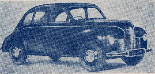
Jowett Javelin from a pre-production sales brochure.
A GATHERING TOGETHER OF DATA FROM VARIOUS SOURCES
Compiled by Mike Allfrey – 1998..
Revised – January, 2007.
CONTENTS – JAVELIN SECTION
Description Page No.
INTRODUCTORY NOTE 5
VEHICLE IDENTIFICATION 5
GENERAL VEHICLE DATA 5
ENGINE PERFORMANCE DATA 5
FUEL SYSTEM 6
IGNITION SYSTEM 6
SUPERSEDING DISTRIBUTOR DATA (AS OF 1998) 6
CRANKCASE DATA 7
CRANKSHAFT AND CONNECTING RODS 7
CRANKSHAFT GRINDING DATA (as of 1998) 8
SPECIAL NOTES FOR GRINDING CRANKSHAFTS 8
LAYSTALL CRANKSHAFT – SPECIAL NOTE 9
PISTON DATA 9
CAMSHAFT DATA 9
VALVE & VALVE SPRING DATA 10
ENGINE LUBRICATION DATA 10
ENGINE COOLING SYSTEM 10
ENGINE BOLT AND NUT TORQUE DATA 11
CLUTCH 11
GEARBOX 11
PROPELLOR SHAFT 12
REAR AXLE 12
FRONT SUSPENSION 12
REAR SUSPENSION 12
SHOCK ABSORBERS 13
STEERING SYSTEM 13
BRAKING SYSTEM 13
WHEELS AND TYRES 14
ELECTRICAL SYSTEM 14
ELECTRICAL COMPONENT details 14
INSTRUMENTS 15
SUMMARY OF JAVELIN ENGINEERING CHANGES 15
SERIES III ENGINE – DISTINGUISHING FEATURES 16
RECONDITIONED ENGINE NOTES 16
TECHNICAL DATA
MANUFACTURER: JOWETT CARS LTD. MODELS: JAVELIN PA – PE
MANUFACTURED FROM: 1947 – 1954
Introductory Note
This document is the result of an attempt to combine all technical data relating to the Jowett Javelin saloon. Some data has been taken from the Auto Trader Service Data No. 208, dated August 26th. 1953, some is from Scientific Magazines Publishing Co., 1952. Some original information has been taken from the Maintenance Manual, published by Jowett Cars Limited. All later information sourced from the Jupiter Owners Auto Club, Jowett Parts (NZ) and local experience. Every effort has been made to maintain accuracy of information. However, due to the Jowett Car Club of Australia Incorporated having no influence on the content of this document nor the changes which may happen, responsibility cannot be accepted by the club for any errors and/or changes.
Vehicle Identification
Post-war Jowett vehicles have a Serial Number system which conveniently identifies the year of manufacture, the type of vehicle (Commercial, Passenger or Sports), the series of that model and the vehicle’s individual number. These numbers were located on Jupiter vehicles as follows:
Engine Number
This is stamped on to a raised plinth which is located on the left hand side front face of the crankcase. It is the same number as the chassis number (Serial Number).
Reconditioned engines have a riveted identification plate located on the rear top surface of the crankcase adjacent to the clutch housing and starter motor pinion.
Chassis & Body Numbers
These are stamped on to a brass plate which is fastened to the upper left hand side of the dash (firewall) and can bee seen after raising the bonnet. Nearby, close to the bonnet hinge, is a plate showing the Briggs Body Number. It should be noted that there is also a chassis number stamped directly into the body frame at the bonnet catch cross member above the grille.
Sample Serial Number Identification
The sample Serial Number E1/PC/12778D, describes a Javelin vehicle which was manufactured in 1951, being a saloon car of the third series. The components of this Serial Number are deciphered as follows:
E = 5 Being the first digit of the decade. ‘A’ = 1, ‘B = 2, ‘C’ = 3 and ‘D’ = 4.
1 = 1 Being the year in the decade.
P = Passenger car.
C = Third build series. ‘A’ = First series, ‘B’ = Second series.
12778D = The individual vehicle number.
The above describes a right hand drive vehicle, if it had been left hand drive the Serial Number would have been E1/PCL/12778D.
General Vehicle Data
Wheelbase 93 in. (236.22 cm) Wheel Track – Front 51 in. (129.54 cm)
Wheel Track – Rear 49 in. (124.46 cm) Ground Clearance 7.5 in. (190.5 mm)
Weight (Dry) 19 cwt. (983.40 kg) Weight (Unladen) 20 cwt (1024 kg)
Weight, Front to Rear Distribution 1215 lbs. (551.1 kg) – 54%, 1043 lbs. (473.1 kg) – 46%
Towing Capacity 15 cwt. (762 kg) Tyre Size 5.25 - 16, 4 ply
Tyre Pressure (F/R) 24/26 psi. (165/180 kPa) Overall Length 168 in. (426.72 cm)
Overall Width 62 in. (157.48 cm) Overall Height 56 in. (142.24 cm)
Engine Performance Data
Number of Cylinders 4
Bore x Stroke: 2.854 x 3.545 inches (72.5 x 90 mm)
Cubic Capacity: 90.9 cu.in. (1486 cc)
RAC Rated Horse Power 13.05
Max. BHP (kW) @ erpm 52.5 (39.2) @ 4100
Max Torque (lb.ft.) @ erpm 76 @ 3000
Maximum BMEP @ erpm 126 psi @ 2600
Compression Ratio 7.2 : 1
Compression Press @ 250 erpm 114 lbs/ins2 (786 kPa)
Average Fuel Consumption 30 to 35 MPG at 40 to 50 MPH
Gearing 15.5 mph per 1000 erpm in top gear
Piston Speed at 66 mph 2500 ft per minute
Fuel System
Note: Early engines had two Zenith 30VM-4, later engines 30VM-5 carburettors. The Jowett Competition Tuning Notes booklet suggested use of 30VM carburettors as used in the later Jupiter.
30VM-4* 30VM-5** 30VM-5 30VM
Zenith Contract Sheet Number C1084 C1130 C1161 C1316
Carburettors, Jet Sizes:
Main 90 90 90 120
Compensating 50 50 50 65
Progression 170# 170+ 110 120
Capacity Tube 2 2 2 2
Screw Over Capacity Well 2.6 2.6 2.6 2.5
Slow Running 50 50 45 45
Choke 23 23 23 27
Needle Seat 2 mm 2 mm 1.5 mm 1.5 mm
Needle Seating Washer 1 mm 1 mm 1 mm 1 mm (2x)
* Before D8/PA/1753 ** After D8/PA/1753
# With 2 mm outlet hole in barrel + With 180 drilling
Fuel Pump (Mechanical) AC (Type U) Driven by push rod from engine oil pump shaft
Fuel Pump Pressure (Static) 1.6 – 2.0 psi. (11.03 – 13.8 kPa)
Fuel Pump Push Rod Length 1.656 in. (42.062 mm)
Wear Limit 0.010 in. (0.25 mm)
Air Cleaner (Before D9/PA/5374) Dry elements in bonnet with wooden silencer
Air Cleaner (After D9/PA/5374) Oil bath in bonnet with wooden silencer
Air Cleaner Oil Capacity 0.33 pint (0.189 litre)
Fuel Tank Capacity 8 gallons (36.4 litres)
Ignition System
Distributor Rotation Clockwise (when viewed from driven end)
Contact Breaker Gap 0.010 – 0.012 in. (0.254 – 0.305 mm) DKY H4A type
0.014 – 0.016 in. (0.356 – 0.406 mm) DM2 type
High Tension Lead Lengths: No. 1 24 in. (610 mm) No. 2 27 in. (686 mm)
No. 3 29 in. (737 mm) No. 4 24 in. (610 mm)
Distributor to Coil 14 in. (356 mm) All 20 strand
Advance Data: DKYH4A DM2
Centrifugal (Crank Deg.) 18 – 22 deg. 18 – 22 deg.
Advance Starts (Crank rpm) 460 – 800 600 – 940
Max. Advance at Crank rpm 2260 1840 – 1960
Cam Angle (Closed Period) 49 ± 4 deg. 60 ± 3 deg.
Contact Spring Tension 20 – 24 oz. (567 – 680 g)
Condenser Capacity 0.2 mf
Firing Point & Order TDC to 3 degrees after TDC, 1 4 2 3
Superseding Distributor Data
Distributor 40115, fitted to Jupiters prior to E2/SA/717, had the following advance curve:
9 – 11 deg. at 1500 distributor rpm (18 – 22 deg. at 3000 engine rpm)
5 – 7 deg. at 800 distributor rpm (10 – 14 deg. at 1600 engine rpm)
0 – 2 deg. at 400 distributor rpm (0 – 4 deg. at 800 engine rpm)
Distributor 40317, fitted to Jupiters after E2/SA/717, having the following advance curve:
9 – 11 deg. at 1300 distributor rpm (18 – 22 deg. at 2600 engine rpm)
3 – 6 deg. at 650 distributor rpm (6 – 12 deg. at 1300 engine rpm)
0.5 – 3.5 deg. at 500 distributor rpm (1 – 7 deg. at 1000 engine rpm)
No advance below 250 distributor rpm (500 engine rpm)
Distributor DVXH4A number 40318 (fitted to the R1 Jupiter) and also the distributor number 40571 have the same advance curve as the 40317 above. The 40571 was replaced by the 40735 which is now (July 1972) replaced by the still current 40795, having this advance curve:
9 – 11 deg. at 1200 distributor rpm (18 – 22 deg. at 2400 engine rpm)
5 – 7 deg. at 600 distributor rpm (10 – 14 deg. at 1200 engine rpm)
0 – 2 deg. at 350 distributor rpm (0 – 4 deg. at 700 engine rpm)
No advance below 225 distributor rpm (450 engine rpm)
Degrees and rpm are quoted at the distributor, and both should be doubled to arrive at the equivalent measured at the engine crankshaft, shown above in brackets.
Sparking Plugs:
Plug Types: Champion L10 (L87YC) Bosch W8 AC
KLG F50 (Water Proof – WF 50) AC 45F
NGK (Japanese) B5HS
Gap Setting 0.020 – 0.025 in. (0.508 – 0.635 mm)
Thread Diameter 0.55 in. (14.0 mm)
Reach 0.5625 in. (14.29 mm)
Crankcase Data
Crankcase Material DTD 133 B aluminium alloy
Carb. Balance Pipe Protrusion 0.009 – 0.015 in. (0.229 – 0.381 mm)
Cylinder Liner Protrusion 0.004 – 0.008 in. (0.102 – 0.203 mm) with solid shims only
Cylinder Liner Material Cast Iron (Vacrit)
Cylinder Liner Oversizes + 0.010” (0.254 mm), + 0.020” (0.508 mm), + 0.030” (0.762 mm)
Cylinder Liner Bore (In Crankcase) 3.1880 – 3.1895 in. (80.975 – 81.013 mm)
Main Bearing Bore Diameter 2.395 in. (60.833 mm)
Camshaft Bearing Bore Diameter 1.501 – 1.503 in. (38.1254 – 38.1762 mm)
Clutch Housing Dedicated to crankcase set
Crankshaft & Connecting Rods
Main Bearings Crank Pins
No. 1 No. 2 No. 3
Diameter 2.25 in. 2.25 in. 2.25 in. 2 in.
Length 1.25 in. 1.25 in. 1.391 in. 1 in.
Running Clearance:
Main Bearings Nos. 1 & 2 – 0.000 – 0.002 in.* No. 3 – 0.0005 – 0.0015 in.*
Crank Pins (Big Ends) 0.000 – 0.0015 in.*
Crankshaft End Float Main Bearings: 0.003 – 0.004 in. Big Ends: 0.004 – 0.008 in.
Journal Under Sizes 0.005#, 0.010, 0.020 in.
Crankshaft Material EN 12° Steel (hardened journals after E0 PB 8902)
Depth of Hardness 0.040 – 0.050 in. (1.02 – 1.27 mm)
Flywheel Spigot Diameter 2.999 – 3.000 in. (76.175 – 76.20 mm)
Starter Ring Gear/Pinion 111/9 (number of teeth)
Permissible Runout 0.003 in. (0.0762 mm) At rear face of flywheel.
Connecting Rod Type Forged ‘H’ type
Connecting Rod Material EN 8 Steel
Big End Bearing Bore Diameter 2.1445 in. – 2.1450 in. (54.4576 – 54.483 mm)
(For Alternative Shells) Clean-up bore to 2.1460 in. – 2.1465 in. (54.508 – 54.521 mm)
Big End Bearing Bore Chamfer 0.125 in. (3.18 mm) at 45°
Small End Bearing Diameter 0.8125 – 0.8132 in. (20.6375 – 20.6553 mm)
Connecting Rod Centres 6.2044 in. ± 0.003 in. (157.592 mm ± 0.0762 mm)
* Theoretical interference becomes positive clearance in running conditions. # 0.005 in. undersize not available for big ends.
Crankshaft Grinding Data (As Of 1998)
With respect to Javelin Models PA to PE the main bearing and big end bearing journals can be ground to the following under sizes – 10, 20, 30 and 40 thou. The following grind specifications apply for the different types of bearing surface being used. It should be noted that, if a white metal rear main bearing set is used in conjunction with either copper/lead or ‘Alutin’ bearings at Nos. 1 & 2 main bearings, the grind tolerances immediately below apply to the rear main journal. The grind tolerances, for white metal bearings (original early type) are as follows:
White Metal Bearings
Main Bearing Standard Size Specification 2.2500” – 2.2485” (57.150 – 57.112 mm)
Big End Bearing Standard Size Specification 2.000” – 1.9985” (50.800 – 50.762 mm)
Main Bearings: First Grind (- 0.010”) 2.240” – 2.2385” (56.896 – 56.858 mm)
Second Grind (- 0.020”) 2.230” – 2.2285” (56.642 – 56.604 mm)
Third Grind (- 0.040”) 2.210” – 2.2085” (56.134 – 56.096 mm)
Big End Bearings: First Grind (- 0.010”) 1.990” – 1.9885” (50.546 – 50.508 mm)
Second Grind (- 0.020”) 1.980” – 1.9785” (50.292 – 50.254 mm)
Third Grind (- 0.040”) 1.960” – 1.9585” (49.784 – 49.746 mm)
(Note: These tolerances apply to the early specification big end bearing surface material.)
Copper-Lead Bearings
It is possible that copper/lead type bearings can be obtained. Should this bearing surface material be used, then a different grind tolerance applies:
Main Bearing Standard Size Specification 2.2505” – 2.2500” (57.163 – 57.150 mm)
Big End Bearing Standard Size Specification 2.000” – 1.9995” (50.800 – 50.787 mm)
Main Bearings: First Grind (- 0.010”) 2.2405” – 2.2400” (56.909 – 56.896 mm)
Second Grind (- 0.020”) 2.2305” – 2.2300” (56.655 – 56.642 mm)
Third Grind (- 0.030”) 2.2205” – 2.2200” (56.401 – 56.388 mm)
Fourth Grind (- 0.040”) 2.2105” – 2.2100” (56.147 – 56.134 mm)
Big End Bearings: First Grind (- 0.010”) 1.9900” – 1.9895” (50.546 – 50.533 mm)
Second Grind (- 0.020”) 1.9800” – 1.9795” (50.292 – 50.279 mm)
Third Grind (- 0.030”) 1.9700” – 1.9695” (50.038 – 50.025 mm)
Fourth Grind (- 0.040”) 1.9600” – 1.9595” (49.784 – 49.771 mm)
(Note: When copper/lead bearing surface is used the crankshaft journals could wear prematurely.)
‘Alutin’ Bearings
It is also possible that “Alutin” type bearings can be obtained. Should this bearing surface material be used, then the following grind specification applies:
Main Bearing Standard Size Specification 2.250” – 2.2498” (57.150 – 57.145 mm)
Big End Bearing Standard Size Specification 2.0000” – 1.9998” (50.800 – 50.795 mm)
Main Bearings: First Grind (- 0.010”) 2.2400” – 2.2398” (56.896 – 56.891 mm)
Second Grind (- 0.020”) 2.2300” – 2.2298” (56.642 – 56.637 mm)
Third Grind (- 0.030”) 2.2200” – 2.2198” (56.388 – 56.383 mm)
Fourth Grind (- 0.040”) 2.2100” – 2.2098” (56.134 – 56.129 mm)
Big End Bearings: First Grind (- 0.010”) 1.9900” – 1.9898” (50.546 – 50.541 mm)
Second Grind (- 0.020”) 1.9800” – 1.9798” (50.292 – 50.287 mm)
Third Grind (- 0.030”) 1.9700” – 1.9698” (50.038 – 50.033 mm)
Fourth Grind (- 0.040”) 1.9600” – 1.9598” (49.784 – 49.779 mm)
SPECIAL NOTES FOR GRINDING CRANKSHAFTS
When grinding the crankshaft at main and big end bearing journals, particular care should be taken to ensure that a suitable radius (0.100” [2.54 mm]) is ground at the journal fillets. Total ovality and taper of each journal should not exceed 0.002” (0.0508 mm). At the journals there must be a high surface finish, with a maximum surface roughness of 12 micro inch.
The spigot end of the crankshaft, where rear main oil seal runs, MUST NOT BE GROUND. This is the spigot for flywheel location.
Laystall Crankshaft (Machined Oval Web) Special Note
Certain precautions are necessary when nitriding Laystall oval-web crankshafts. This note has been taken from a letter from Laystall Engineering Co. Ltd., London in 1970, following a query from a club member who had a shaft reground to within limits specified and then nitrided. Two main bearings were outside limits, and the crankshaft was too stiff to turn after assembly.
“. . . We (Laystalls) normally nitride these shafts for 50 hours, giving a depth of hardness of 0.012” – 0.016”, the maximum hardness is down to approximately 0.006” – 0.008” (0.152 – 0.203 mm) and then gradually tapers away . . . . (and) there is a slight build up of approximately 0.0005” (0.0127 mm). it is advisable to grind both before and after nitriding, due to possible distortion that can take place when the stresses in the steel are released during nitriding, leaving approximately 0.003” – 0.005” (0.0762 – 0.127 mm) on diameter for this operation.”
Note: A photocopy of these pages should be handed to whoever is grinding the crankshaft.
Piston Data
Material HG .413 Aluminium silicon die casting
Nominal Diameter 2.8542 – 208534 in. (72.497 – 72.476 mm) at gudgeon pin c/l
Clearance (Skirt) 0.0015 in. (0.0381 mm)
Over Sizes available 0.010, 0.020, 0.030, 0.040 in.
Weight c/w Rings, Pin & Circlips 13.75 oz. (389.8 grammes)
Gudgeon Pin:
Material S.14 Steel
Diameter 0.8125 in. (20.64 mm)
Fit in Piston 0.000 – 0.0004 in. (0.000 – 0.01016 mm) (Clearance)
Fit in Connecting Rod (Small End) 0.000 – 0.0007 in. (0.000 – 0.01778 mm) (Clearance)
Compression Height 1.555 in. (39.5 mm)
Piston Rings: Compression Oil Control
Number of Rings 2 1
Ring Gap in Cylinder 0.007 – 0.015 in. 0.007 – 0.015 in.
(0.178 – 0.381 mm) (0.178 – 0.381 mm)
Side Clearance in Grooves 0.0015 – 0.002 in. 0.0015 – 0.002 in.
(0.038 – 0.051 mm) (0.038 – 0.051 mm)
Width of Rings 0.156 in. (3.96 mm) 0.156 in. (3.96 mm)
Camshaft Data
Camshaft Material EN 32B Steel or cast iron
Bearing Journal Diameter 1.50 in. (38.10 mm)
Bearing Journal Length 1.156 in. (29.362 mm)
Bearing Clearance 0.001 – 0.003 in. (0.025 – 0.076 mm)
Wear Limit on Journals 0.002 – 0.003 in. (0.051 – 0.076 mm)
Overall Height of Cam – Tip to Base 1.266 in. (32.156 mm)
Amount of Lift 0.224 in. (5.69 mm)
Valve Timing Inlet opens – 12º BTDC, inlet closes – 53º ABDC
Exhaust opens – 50º BBDC, exhaust closes – 15º ATDC
Camshaft End Float With engine stopped. To adjust – screw adjusting screw in to light contact with the camshaft, then back off one eighth of a turn and tighten lock nut while holding adjusting screw in set position.
Camshaft Drive Endless Duplex chain
Timing Chain Pitch 0.375 in. (Renold Duplex Chain)
Timing Chain Number of pitches 56 (Endless Chain – Renold)
Number of Teeth Chain Wheels:
Crankshaft 21
Camshaft 42
Dimension Between Wheel Centres 4.413 – 4.415 in. (112.09 – 112.14 mm)
Valve & Valve Spring Data
Inlet Exhaust
Head Diameter 1.4375 in. (36.51 mm) 1.21875 in. (32.56 mm)
Stem Diameter 0.3125 in. (7.94 mm) 0.3125 in. (7.94 mm)
Face Angle 30º 45º
Valve Material:
Exhaust XB Austentic steel
Inlet Silicon chrome steel
Valve Guide Material Close grain cast iron
Valve Guide Protrusion 0.6875 in. (17.5 mm) above cylinder head outer surface
Tappet Clearance (Engine Cold) 0.003 in. (0.0762 mm) 0.006 in. (0.1524 mm)
Valve Springs Inner Outer
Free Length 1.935 in. (49.15 mm) 2.022 in. (51.36 mm)
Fitted Length 1.455 in. (36.96 mm) 1.468 in. (37.29 mm)
Static Load 58 lb. (25.9 kg) 71 lb. (31.6 kg)
External Diameter 0.997 in. (25.32 mm) 1.378 in. (35.00 mm)
Internal Diameter 0.753 in. (19.13 mm) 1.0588 in. (26.89 mm)
Wire Diameter 10.5 swg 8 swg
Engine Lubrication Data
Lubrication System Pressure 50 – 60 psi. (345 – 414 kPa) at 2000 erpm before E1/PC/15098
65 – 70 psi. (448 – 483 kPa) at 2000 erpm after E1/PC/15098
Ratio of Pump Drive Half engine speed
Pump Capacity 3 gal. (13.64 litres) at 4000 erpm
Pump Internal Gears:
Number of Teeth 10
Pitch Circle 1.079 in. (27.407 mm)
Gear Bore Diameter 0.5002 – 0.4997 in. (12.705 – 12.692 mm)
Gear Overall Diameter 1.278 – 1.279 in. (32.461 – 32.487 mm)
Clearance, Gears to Cover 0.004 in. (0.102 mm) Including Gasket
Balance Valve Opens at 7 psi. (48.26 kPa)
Relief Valve Early Engines Non-adjustable SIII Engines Adjustable
Relief Valve Spring Length 2.0 in. (50.8 mm) – Before E1/PC/15098
Relief Valve Spring Length 1.75 in. (44.45 mm) – After E1/PC/15098
Spring Load at 1.1875” (30.162 mm) 9 lbs. (4.08 kg) – Before E1/PC/15098
Spring Load at 1.1875” 10 lbs. (4.54 kg) – After E1/PC/15098
Spring Rate 11.08 lbs. per inch (1.978 kg. per cm) – Before E1/PC/15098
Spring Rate 19.78 lbs. per inch (3.20 kg. per cm) – After E1/PC/15098
Oil Pressure Switch Breaks contact at 8 psi (55.2 kPa)
Sump Capacity 9 pints (5.11 litres) – Less oil cooler
Sump Capacity 10 pints (5.7 litres) – Includes oil cooler
Engine Cooling System
Water Pump Capacity Flow – 7.5 gallons (34.1 litres) per minute at 2100 pump rpm
Drive Belt B44
Radiator Type 4 Row fin and tube
Radiator Dimensions 17.812 in. (452 mm) wide x 18.75 in. (476 mm) deep
Capacity of System 2 gallons (9.1 litres)
Capacity of Heater 1 pint (0.57 litre)
Corrosion Inhibitorã Tectalloy Xtreme Gold – 1 litre makes 15 litres coolant, Mix with soft water
(AS 2108-1977)
Antifreezeã Castrol Anti Freeze/Anti Boil 50% soft water mix (AS2108-84)
Thermostat Opens at 167º F (75 ºC)
ã Cooling system should be drained, flushed and filled with fresh mix of corrosion inhibitor or antifreeze at two year intervals. Top-up coolant should be thoroughly pre-mixed as indicated above. Use corrosion inhibitor when temperature does not drop below 0 ºC. Do not mix products.
Engine Bolt & Nut Torque Data
Description Bolt/Stud Size Specified Torque
Cylinder Head Nut No. 1 0.375 in. 28 lb.ft.*
Cylinder Head Nuts (Remainder) 0.375 in. 37.5 lb.ft.**
Big End Bolts 0.375 in 35 lb.ft.
Flywheel Bolts 0.4375 in. 60 lb.ft
Crankcase Through Bolts 0.5625 in. 75 lb.ft.
* Short thread into oil gallery, drilled stud.
** For cylinder liners on solid copper shims.
Cylinder Head Nuts Clarification of cylinder head nut torque – in 1963 Jowett Engineering were attaching labels to their reconditioned Javelin engines drawing attention to the revised cylinder head nut torque wrench setting:
“. . . Cylinder head torque wrench setting now reduced to 450 inch-lbs.” This figure of 37.5 lb.ft. in applying to ‘O’ ring liner engines is also relevant to the present practice of using copper liner seals.
Clutch
Manufacturer Borg & Beck
Type 7¼ AS
Friction Disc
External Diameter 7.25 in. (184 mm)
Internal Diameter 5.00 in. (127 mm)
Lining Material Thickness 0.125 in. (3.2 mm)
Lining Material – RHD Ferodo moulded asbestos (now superseded)
Lining Material – LHD Ferodo woven yarn (now superseded)
Drive Springs 3 – blue
Overrun Springs 3 – green
Pressure Plate Assembly
Release Lever Setting 1.665 in. (42.29 mm) – Tip of lever above flywheel face
Maximum Variation in Height 1.655 – 1.665 in. (42.037 – 42.29 mm) with bias stressed to the
top limit rather than the bottom
Pressure Springs – RHD 3 – yellow 120 lbs. (54.432 kg)
3 – red 135 lbs. (61.236 kg)
Pressure Springs – LHD 3 – yellow 120 lbs. (54.432 kg)
3 – Maroon 105 lbs. (47.628 kg)
Spring Data:
Red Free length – 1.96 in. (49.784 mm)
Rating – 223 lbs. per inch (41 kg per cm)
Yellow Free Length – 2.255 in. (57.277 mm)
Rating – 142 lbs. per inch (25.5 kg per cm)
Maroon Free length – 2.150 in. (54.61 mm)
Rating – 142 lbs. per inch (25.5 kg per cm)
Gearbox
Speeds 4 & Reverse
Synchronisers 2nd. 3rd. 4th. speeds
Gear Ratios:
Before Eng. No. E1/PC/11270 First – 3.88:1, Second – 2.38:1, Third – 1.50:1, Fourth – 1:1,
Reverse – 3.88:1
After Eng. No. E1/PC/11270 First – 3.56:1, Second – 2.17:1, Third – 1.37:1, Fourth – 1:1,
Reverse – 3.56:1
Oil Capacity 1 pint (0.57 litre)
Propellor Shaft
Type and Make of Joints Layrub 55 x 1.125
Number of Joints 3
Maximum Longitudinal Travel 0.563 in. (14.29 mm)
Outside Diameter of Shaft 2 in. (50.8 mm)
Rear Axle
Manufacturer Salisbury
Type 3HA Hypoid bevel drive
Crown Wheel/Pinion Teeth 39/8
Ratio 4.875 : 1
Axle Shaft End Float 0.006 – 0.008 in. (0.152 – 0.203 mm)
Crown Wheel/Pinion Backlash 0.004 in. (0.102 mm) Minimum
Differential Side Bearings (2) Timken 24788/4 and 24721/4
Pinion Bearing (Front) Timken 02872/4
Pinion Bearing (Rear) Timken 315931–3150/4
Pinion Bearing Pre-load 8 – 12 lb.ins. (9.2 – 13.8 kg.cm.)
Drive Gear Pre-load Shim Allowance 0.008 in. (0.203 mm)
Drive Gear Bolts – Torque 40 – 50 lb.ft. (5.51 – 6.9 kg.m.)
Oil Capacity 2.25 pints (1.57 litres) SAE 90 Hypoid Oil
Front Suspension
Type Unequal Arm Transverse Link
Length Top Link 7.75”
Length Bottom Link (Spring Arm) 14.94”
King Pin Inclination 10°
King Pin Offset 0.75”
Total Wheel Movement 6.375”
Normal Load to Rebound 1.875”
Normal Load to Bump 4.50”
Normal Wheel Camber 0°
Camber at Rebound 1 – ½°
Negative. Camber at Bump 1 – ½° Negative
Caster Angle 0°
Torsion Bar Spring Diameter 0.880”
Effective length 36.25”
Torsion Bar Material Silicone-Manganese Spring Steel
Normal Load on Spring .Arm 672 lbs.
Stress in Torsion Bar at this Load 33.5 tons per square inch
Stress at Full Bump 55.9 tons per square inch
Wheel Deflection at Normal Load 7”
Spring Periodicity at Normal Load 71 cycles per minute
Rear Suspension
Spring Arm Length 13.625”
Size of Torsion Bar As for Front Suspension
Total Wheel Movement 7.25”
Normal Load to Re bound 3”
Normal Load to Bump 4.25”
Normal Load on Spring Arm 712 Lbs.
Stress in Torsion Bar at this Load 32.8 tons per square inch
Stress in Torsion Bar at Full Bump 55.5 tons per square inch
Wheel Deflection at Normal Load 6.5”.
Spring Periodicity at Noma1 Load 73 cycles per minute
Shock Absorbers
Type Woodhead Monroe, 1” diameter
Front:
Closed Length 8”
Extended Length 11.5”
Rear:
Closed Length 11.75”
Extended Length 19”.
Steering System
Castor Angle* 0°
Camber Angle Nil (with upper links horizontal)
King Pin Inclination** 10º
Front Wheel Tracking Parallel to 0.0625 (1.6 mm) toe-out
Chassis Height from Ground 10.25 in. (260.35 mm) – at front of gearbox cross member
Steering Box Ratio 12:1
Vehicle Turning Circle 32 ft. (9.754 metres)
Number of Turns, Lock to Lock 3
* Vehicle unladen.
** King pins offset 0.8125 in. (20.64 mm)
Braking System
Manufacturer Girling
Before E0/PB/10594:
Type – Front Hydraulic, with single hydraulic expander unit
Type – Rear Mechanical, with cable, compensator and rod actuation
Drum Diameter 9 in. (228.6 mm)
Drum Material Malleable iron
Lining Length 7.3125 in. (185.74 mm)
Lining Width (Front) 1.5 in. (38.1 mm)
Lining Width (Rear) 1.25 in. (31.75 mm)
Friction Lining Area 88 in2. (567.74 cm2)
Lining Thickness 0.1875 in. (4.76 mm)
Number of Rivets Per Shoe 10
After E0/PB/10594:
Type – Front Full hydraulic, 2 leading shoe
Type – Rear Full hydraulic, fully floating incorporating hand brake actuator
Drum Material Malleable iron
Lining Length 8.75 in. (222.25 mm)
Lining Width 1.75 in. (44.45 mm)
Friction Lining Area 123 in2. (793.55 cm2)
Lining Thickness 0.1875 in. (4.76 mm)
Number of Rivets Per Shoe 10
Wheel Cylinder Diameter (Front) 0.875 in. (22.23 mm)
Wheel Cylinder Diameter (Rear) 0.875 in. (22.23 mm)
Braking Effort (Front) 65%
Braking Effort (Rear) 35%
Brake Pedal Ratio 6 : 1
Brake Retardation at 30 mph (One up)
Pedal Pressure Stopping Distance
25 lbs. (11.3 kg) 130 ft. (39.6 metres)
50 lbs. (22.7 kg) 59 ft. (18 metres)
75 lbs. (34 kg) 43 ft. (13.1 metres)
100 lbs. (45.4 kg) 39 ft. (11.9 metres)
Brake Fluid (For Both Types) Castrol crimson brake fluid (authentic), Castrol Ultra-Stop
Colour – Amber. AS1960-1983 Grade 3.
Ford spec. ESW-FM6C-2, Leyland HBF-6
Brake Fluid Capacity 1 pint (0.57 litre)
Wheels And Tyres
Type of Wheel Steel disc
Wheel Manufacturer Dunlop
Wheel Size 3.00 x 16
Tyre Size 5.25 – 16 4 Ply
Tyre Pressure (Front) Normal – 24 psi. (166 kPa)
Tyre Pressure (Rear) Normal – 26 psi. (180 kPa)
Electrical System
Manufacturer Lucas
Component Summary: Model No. Part No.
Battery 1 – 12 volt GTW 9A –
Dynamo C39 PV2 22438
Starter Motor M 35 G 25025
Solenoid Starter Switch ST 950 76411
Ign. & Lighting Switch PLC 6 34067
Ign. & Lighting Switch PRS 3 31270
Control Box – Early RF 95 37076
Control Box – Later RB 106 37139
Distributor – Early DKY H4A 40115
Distributor – Later DM2 40317, 40318, 40571, 40735, 40795
Ignition Coil B 12 45012
Headlamp – RHD 7 inch
Headlamp – LHD 7 inch
Side Lamp 489 32139
Tail & Stop Lamp
Number Plate Lamp (Deluxe) 487-1 53093
Trafficator 8F 40 N 54041
Trafficator Switch (Smiths) – –
Trafficator Switch (Trico) – 031046
Component Summary: Model No. Part No.
Screen Wiper – Early CR 4 75088
Screen Wiper – Later CRT 14 75151
Horn – Low Note WT 29 690798
Horn – High Note WT 29 690799
Horn Relay SB 40 33116B
Cigar Lighter (Smiths) – SK40503/10
Bulbs: Voltage Wattage Cap
Headlamps 12 36/36 Pre-focus
Side & Number Plate Lamps 12 6 MCS
Tail & Stop Lamps 12 6/24 SBC*
Boot Lamp 12 6 Lucas 207
Roof Lamp 12 6 Festoon
Panel & Warning Lamps 12 2.4 MCS
Trafficators 12 3 Festoon (Lucas 256)
* Offset pins for bayonet.
Fuses 3 x 25 amp
Wiring Harness Standard Lucas colour codes
Electrical Component Details
Battery:
Voltage 12 volts
Earth Terminal Positive
Number of Plates/Cell 9
Capacity 51 ampere hours at 10 hour rate
Height 8 in. (203 mm)
Width 6.75 in. (172 mm)
Length 12.5 in. (318 mm)
Starter Motor:
Lock Torque 9.3 lb. ft.
Lock Voltage 7.9 volts
Lock Current Draw 335 amps
Brush Spring Tension 32 – 40 oz. (907 – 1134 g)
Number of Pinion Teeth 9
Cranking Ratio 12 : 3
Dynamo:
Maximum Output 15 amps at 13.5 volts
Cut-in Speed 1050 – 1200 rpm at 13 volts
Field Resistance 6.1 Ohms
Brush Spring Tension 22 – 25 oz. (624 – 709 g)
Direction of Rotation Clockwise (commutator end)
Control Box Electrical Settings 10º C (50º F) 16.1 – 16.7 volts
20º C (68º F) 15.8 – 16.4 volts
30º C (86º F) 15.6 – 16.2 volts
40º C (104º F) 15.3 – 15.9 volts
Horn Current Drain 12 – 15 amps
Wiper Motor Current Drain 2 – 3 amps
Instruments
Temperature Gauge Smiths, X70971/2
Engine Oil Pressure Smiths, X76634/1
Fuel Gauge Smiths,
Speedometer Smiths, X70802/9
Ammeter Lucas, 36135A
Clock Smiths,
Summary Of Javelin Engineering Changes
Change Description Effective From
Flywheel and clutch assembly balanced as a unit. D8 PA 100
Exhaust manifold flanges increased in diameter. D8 PA 164
Redesigned air silencer. D8 PA 185
Hydraulic tappet fitted with end cover. D8 PA 781
Expansion chamber fitted to exhaust system. D8 PA 997
Carburettors Changed from 30VM4 to 30VM5 (Type ‘M’). D8 PA 1753
Flywheel bolts, diameter increased from 3/8“ to 7/16”. D9 PA 2200
Dynamo changed from C.45 to C.39. D9 PA 2259
Connecting rod bolts, diameter increased from 5/16” to 3/8“. D9 PA 2373
Spring arm trunnion bushes pressed on, retaining nuts deleted. D9 PA 2554
Steering box eccentric bush incorporated. D9 PA 2871
Exhaust system, single rear silencer. D9 PA 3138
12 volt single battery fitted. D9 PA 3696
Copper-lead connecting rod bearings fitted. D9 PA 3794
Fitting of starter solenoid and electrical harness alterations (RHD). D9 PA 4243
Copper-lead front and centre main bearings fitted. D9 PA 4322
Oil bath air filter fitted (export only). D9 PA 4431
Oil bath air filter fitted (all models). D9 PA 5374
Vacrom piston rings fitted (T/C 27). D9 PA 5756
Modified water pump (T/C 26). D9 PA 5857
Front suspension lubrication, revised method (T/C 27). D9PB 5979
Adjustable steering ball joints fitted (RHD). D9 PB 6572
Adjustable steering ball joints fitted (all models). E0 PB 6801
Exhaust system, introduction of detachable tail pipe. E0 PB 7509
Redesigned rear timing case cover. E0 PB 7676
Introduction of detachable exhaust tail pipe. E0 PB 8276
Trico type windshield wiper blades fitted. E0 PB 8276
New type steering link fitted (‘H’ section stamping). E0 PB 8313
Oil cup added to water pump housing. E0 PB 8472
Small end bearing changed from ‘Glacier’ to ‘Clevite’ metal. E0 PB 8737
Introduction of strengthened cylinder liners and ‘barrel ground’ pistons. E0 PB 8825
Hardened crankshaft fitted (RHD). E0 PB 8902
Hardened crankshaft fitted (LHD). E0 PB 8937
Change to screws in air filter assembly. E0 PB 8950
Horn relay fitted to horn wiring circuit. E0 PB 9293
Engine oil filter outer casing strengthened. E0 PB 9423
Main bearing dowel drilled. E0 PB 9540
Engine oil delivery pipe union wired for locking purposes. E0 PB 9860
New type lower fixing arrangement for front shock absorbers. E0 PB 9877
Steel sump tray assembly. E0 PB 9878
Reinforced front engine mountings (vertical stay deleted). E0 PB 10450
Introduction of serrated connecting rod assemblies. E0 PB 10506
Introduction of four wheel hydraulic braking system. E0 PB 10594
Redesigned steering rod ball joints. E0 PB 10789
Change to gear ratios. E0 PC 11270
1951 Javelin model commences from – E0 PC 11326
Solid type tappet fitted (RHD). E0 PC 11907
Solid type tappet fitted (LHD). E0 PC 11940
Adjustable type selector and gear change links (RHD). E0 PC 12340
New ‘clear view’ steering wheel and lengthened steering column. E0 PC 13111
New design oil pump relief valve and spring, pressure now 70 psi. E1 PC 15098
Redesigned front grille (die cast) and bonnet motif. E0 PC 15631
Rubber bonded exhaust system mountings. E0 PC 15432
Increased strength front shock absorbers. E1 PC 16500
Full flow engine oil filter (Tecalemit). E1 PC 16603
Lubrication groove, centre main crankshaft bearing. E1 PC 16744
Sludge release hole, big end bearings. E1 PC 17402
Cylinder head gasket support. E1 PC 17900
Water pump modifications. E1 PC 18140
Gearbox extension bearing washer. E1 PC 18141
Connecting rod bearings, drilled hole in connecting rod half shell deleted. E1 PC 18646
Throttle rod assembly, redesigned clamp bolts (RHD & LHD). E1PC 18550
Engine oil return from release valve into suction pipe (adjustable valve). E1 PC 18985
Camshaft and chainwheel with vernier adjustment. E1 PD 19295
Improved waterproof plug lead covers. E1 PD 19760
Introduction of adjustable gear change stay (RHD & LHD). E1 PD 20135
Revised taper at water pump shaft and fan hub introduced. E2 PD 20379
Deletion of oil sludge drilling in connecting rod cap. E2 PD 20977
Introduction of Lucas DM2 model distributor. E2 PD 21016
Introduction of petrol filter in feed pipe. E2 PD 21147
Rubber bushed front suspension introduced. E2 PD 21868
Updated crankshaft introduced. E3 PE 22873
Engine lubricating oil pump with extended body introduced. E3 PE 23122
‘O’ Ring type cylinder liner seal introduced. E3 PE 23184
Adjustable camshaft end-float introduced. E3 PE 23643
Series III Engine – Distinguishing Features
1. Stiffer crankcase and enlarged oil ways to improve oil flow to main and big end bearings. Crankcase can be identified by ‘3’ stamped on upper front face of RHS casing. Also internal cross webbing to stiffen main bearing webs. Enlarged area above longitudinal oil galleries. Final crankcases had rear cylinder head studs screwed through coolant inlet ports.
2. Large radii crankshaft with or without lightening holes.
3. Adjustable camshaft thrust pad.
4. No splash protection plate on cylinder head (which necessitated the fitting of the latest sparking plug water proofing modifications). The combustion chamber was polished and slightly modified in shape.
5. Improved engine oil pump, upper housing changed to lower the pump body closer to oil level. Oil pump now featured relief valve venting to suction side of pump. Relief valve adjustable. Delivery pipe enlarged.
6. The fitting of an improved type rear timing cover with larger oil cooler banjo fittings.
Reconditioned Engine Notes
Jowett Engineering advised in 1960 that, if the engine number is prefixed with the letter ‘R’, it indicates a factory replacement unit. In order to clarify the position regarding replacement engines, it can be said that any engine bearing a number later than ‘R’ 10,000, will be the equivalent of a Series III engine. The following shows reconditioning practice since Series III engines were introduced.
1. In the instance where a pre-Series III crankcase is used, machined work is carried out in a number of places on the crankcase to improve the flow of oil to the main bearings, and as a consequence, to the big end bearings. The cylinder head stud holes in the crankcase are counter bored and the crankcase machined and fitted with new type oil gallery plugs. By these means most of the benefits of the Series III crankcase are obtained.
2. Nothing earlier than a Series III crankshaft is fitted, in fact all present engines are fitted with an improved shaft i.e. Blacksided or Oval-Web.
3. All reconditioned engines are fitted with the adjustable camshaft thrust peg.
4. Cylinder head combustion chambers are being polished and modified.
5. Improved engine oil pump base with adjustable relief valve features. In many cases the pump with extended body is fitted. All pumps are tested to a higher standard than was originally used in production of Series III engines.
6. All reconditioned engines have the improved rear timing case cover fitted.
. ![]()
JOWETT JUPITER
TECHNICAL DATA
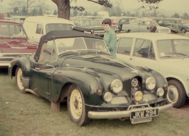
Jowett Jupiter – 1950. Photographed in summer 1968.
A GATHERING TOGETHER OF DATA FROM VARIOUS SOURCES
Compiled by Mike Allfrey – 1998..
Revised – January, 2007.
CONTENTS – JUPITER SECTION
Description Page No.
INTRODUCTORY NOTE 20
VEHICLE IDENTIFICATION 20
GENERAL VEHICLE DATA 20
ENGINE PERFORMANCE DATA 20
FUEL SYSTEM 21
IGNITION SYSTEM 21
SUPERSEDING DISTRIBUTOR DATA 21
CRANKCASE DATA 22
CRANKSHAFT AND CONNECTING RODS 22
CRANKSHAFT GRINDING DATA (as of 1998) 23
SPECIAL NOTE FOR GRINDING CRANKSHAFTS 23
LAYSTALL CRANKSHAFT – SPECIAL NOTE 23
PISTON DATA 24
CAMSHAFT DATA 24
VALVE & VALVE SPRING DATA 25
ENGINE LUBRICATION DATA 25
ENGINE COOLING SYSTEM 25
ENGINE BOLT AND NUT TORQUE DATA 26
CLUTCH 26
GEARBOX 26
ROAD SPEED CHART 27
PROPELLOR SHAFT 27
REAR AXLE 27
FRONT SUSPENSION 28
REAR SUSPENSION 28
SHOCK ABSORBERS 28
STEERING SYSTEM 28
BRAKING SYSTEM 29
WHEELS & TYRES 29
ELECTRICAL SYSTEM 30
ELECTRICAL COMPONENT DETAILS30 30
LUCAS PARTS LISTING 31
INSTRUMENTS 33
SUMMARY OF ENGINEERING CHANGES 33
SERIES III ENGINE – DISTINGUISHING FEATURES 33
RECONDITIONED ENGINE NOTES 33
TECHNICAL DATA
MANUFACTURER: JOWETT CARS LTD. MODELS: JUPITER SA & SC
MANUFACTURED FROM: 1950 – 1954
Introductory Note
This document is the result of an attempt to combine all technical data relating to the Jowett Jupiter sport scar. Original data has been taken from the Auto Trader Service Data No. 208, dated August 26th. 1953. Some original information has been taken from the Maintenance Manual, published by Jowett Cars Limited.
All later information sourced from the Jupiter Owners Auto Club, Jowett Parts (NZ) and local experience. Every effort has been made to maintain accuracy of information. However, due to the Jowett Car Club of Australia Incorporated having no influence on this document nor the changes which may happen, responsibility cannot be accepted by the club for any errors and/or changes.
Vehicle Identification
Post-war Jowett vehicles have a Serial Number system which conveniently identifies the year of manufacture, the type of vehicle (Commercial, Passenger or Sports), the series of that model and the vehicle’s individual number. These numbers were located on Jupiter vehicles as follows:
Engine Number
This is stamped on to a raised plinth which is located on the left hand side front face of the crankcase.
Reconditioned engines have a riveted identification plate located on the rear top surface of the crankcase adjacent to the clutch housing and starter motor pinion.
Chassis & Body Numbers
These are stamped on to a plate which is fastened to the right hand side front wing apron. It should be noted that there is also a chassis number stamped directly into the chassis frame at the radiator mount tower (early cars) or on the left hand bonnet catch bracket on the chassis front cross member.
Sample Serial Number Identification
The sample Serial Number E0/SA/42R, describes a Jupiter vehicle which was manufactured in 1950, being a sports car of the first series. The components of this Serial Number are deciphered as follows:
E = 5 Being the first digit of the decade. ‘A’ = 1, ‘B = 2, ‘C’ = 3 and ‘D’ = 4.
0 = 0 Being the year in the decade.
S = Sports car.
A = First build series. ‘A’ = First series, ‘B’ = Second series.
(Note – ‘B’ was not used in the case of the Jupiter)
42R = The individual vehicle number.
The above describes a right hand drive vehicle, if it had been left hand drive the Serial Number would have been E0/SAL/42R.
The second series was identified by having ‘SC’ within the Serial Number and that model was described as the MK Ia. There was a third series, the R4 that was to have been introduced, but did not reach full production.
General Vehicle Data
Wheelbase 93 in. (236.22 cm) Wheel Track – Front 51 in. (129.54 cm)
Wheel Track – Rear 49 in. (124.46 cm) Ground Clearance 8 in. (203.2 mm)
Weight (Dry) 16 cwt. (812.85 kg) Tyre Size 5.50 - 16, 4 ply
Tyre Pressure 26 psi. (179 kPa) Overall Length 168 in. (426.72 cm)
Overall Width 62 in. (157.48 cm) Overall Height 56 in. (142.24 cm)
Engine Performance Data
Number of Cylinders 4
Bore x Stroke: 2.854 x 3.54 inches (72.5 x 90 mm)
Cubic Capacity: 90.9 cu.in. (1486 cc)
RAC Rated Horse Power 13.05
Max. BHP (kW) @ erpm 62.5 (46.6) @ 4500
Max Torque (lb.ft.) @ erpm 84 @ 3000
Compression Ratio 8 : 1
Compression Press @ 250 erpm 130 lbs/ins2 (896 kPa)
Gearing 17 mph per 1000 erpm in top gear
Fuel System
Note: Before Engine No. E2/SA/657 2 - type 30VIG-5, from Engine No. E2/SA/657 2 - type 30VM
30VIG-5 30VM
Zenith Contract Sheet Number C1245 C1316
Carburettors, Jet Sizes:
Main 105 120
Compensating 60 65
Pump Jet 90 –
Progression – 120
Leak 70 –
Vent – 2.5
Slow Running 45 45
Choke 26 27
Needle Seat 1.5 mm 1.5 mm
Needle Seating Washer 1 mm 1 mm (Plus Deflector)
Fuel Pump (Scuttle Mount) SU Type L electric (before E1/SA/439)
Fuel Pump (Chassis Mount) SU Type PP36L electric (after E1/SA/439)
Fuel Pump Pressure (Type L) 0.75 – 1.0 psi. (5.2 – 6.9 kPa)
Fuel Pump Pressure (Type PP36L) 1.5 – 2 psi. (10.3 – 13.8 kPa)
Air Cleaner Vokes Dry Type DX39868 (before E2/SA/590)
Air Cleaners AC Dry Type 1579035 (after E2/SA/590)
Fuel Tank Capacity (SA) Model 10 gallons (45.5 litres)
Fuel Tank Capacity (SC) Model 8 gallons (36.4 litres)
Ignition System
Distributor Rotation Clockwise (when viewed from driven end)
Contact Breaker Gap 0.010 – 0.012 in. (0.254 – 0.305 mm) DKY H4A type
0.014 – 0.016 in. (0.356 – 0.406 mm) DM2 type
High Tension Lead Lengths: No. 1 24 in. (610 mm) No. 2 27 in. (686 mm)
No. 3 29 in. (737 mm) No. 4 24 in. (610 mm)
Distributor to Coil 14 in. (356 mm) All 20 strand
Advance Data: DKYH4A DM2
Centrifugal (Crank Deg.) 18 – 22 deg. 18 – 22 deg.
Advance Starts (Crank rpm) 460 – 800 600 – 940
Max. Advance at Crank rpm 2260 1840 – 1960
Cam Angle (Closed Period) 49 ± 4 deg. 60 ± 3 deg.
Contact Spring Tension 20 – 24 oz. (567 – 680 g)
Condenser Capacity 0.2 mf
Superseding Distributor Data
Distributor 40115, fitted to Jupiters prior to E2/SA/717, had the following advance curve:
9 – 11 deg. at 1500 distributor rpm (18 – 22 deg. at 3000 engine rpm)
5 – 7 deg. at 800 distributor rpm (10 – 14 deg. at 1600 engine rpm)
0 – 2 deg. at 400 distributor rpm (0 – 4 deg. at 800 engine rpm)
Distributor 40317, fitted to Jupiters after E2/SA/717, having the following advance curve:
9 – 11 deg. at 1300 distributor rpm (18 – 22 deg. at 2600 engine rpm)
3 – 6 deg. at 650 distributor rpm (6 – 12 deg. at 1300 engine rpm)
0.5 – 3.5 deg. at 500 distributor rpm (1 – 7 deg. at 1000 engine rpm)
No advance below 250 distributor rpm (500 engine rpm)
Distributor DVXH4A number 40318 (fitted to the R1 Jupiter) and also the distributor number 40571 have the same advance curve as the 40317 above. The 40571 was replaced by the 40735 which is now (July 1972) replaced by the still current 40795, having this advance curve:
9 – 11 deg. at 1200 distributor rpm (18 – 22 deg. at 2400 engine rpm)
5 – 7 deg. at 600 distributor rpm (10 – 14 deg. at 1200 engine rpm)
0 – 2 deg. at 350 distributor rpm (0 – 4 deg. at 700 engine rpm)
No advance below 225 distributor rpm (450 engine rpm)
Degrees and rpm are quoted at the distributor, and both should be doubled to arrive at the equivalent measured at the engine crankshaft, shown above in brackets.
Firing Point & Order TDC to 3 degrees after TDC, 1 - 4 - 2 - 3
Sparking Plugs:
Plug Type Champion L10 S (or L87YC)
Bosch W8 AC (or W6 BC)
KLG F70 (Water Proof – WF 70)
AC 45F
NGK (Japanese) B5HS
Gap Setting 0.020 – 0.025 in. (0.508 – 0.635 mm)
Thread Diameter 0.55 in. (14.0 mm)
Reach 0.5625 in. (14.29 mm)
Crankcase Data
Crankcase Material DTD 133 B aluminium alloy
Carb. Balance Pipe Protrusion 0.009 – 0.015 in. (0.229 – 0.381 mm)
Cylinder Liner Protrusion 0.004 – 0.008 in. (0.102 – 0.203 mm) with solid shims only
Cylinder Liner Material Cast Iron (Vacrit)
Cylinder Liner Oversizes + 0.010” (0.254 mm), + 0.020” (0.508 mm), + 0.030” (0.762 mm)
Cylinder Liner Bore (In Crankcase) 3.1880 – 3.1895 in. (80.975 – 81.013 mm)
Main Bearing Bore Diameter 2.395 in. (60.833 mm)
Camshaft Bearing Bore Diameter 1.501 – 1.503 in. (38.1254 – 38.1762 mm)
Clutch Housing Dedicated to crankcase set
Crankshaft & Connecting Rods
Main Bearings Crank Pins
No. 1 No. 2 No. 3
Diameter 2.25 in. 2.25 in. 2.25 in. 2 in.
Length 1.25 in. 1.25 in. 1.391 in. 1 in.
Running Clearance:
Main Bearings Nos. 1 & 2 – 0.000 – 0.002 in.* No. 3 – 0.0005 – 0.0015 in.*
Crank Pins (Big Ends) 0.000 – 0.0015 in.*
Crankshaft End Float Main Bearings: 0.003 – 0.004 in. Big Ends: 0.004 – 0.008 in.
Journal Under Sizes 0.005#, 0.010, 0.020 in.
Crankshaft Material EN 12° Steel (hardened journals after Javelin E0 PB 8902)
Depth of Hardness 0.040 – 0.050 in. (1.02 – 1.27 mm)
Flywheel Spigot Diameter 2.999 – 3.000 in. (76.175 – 76.20 mm)
Starter Ring Gear/Pinion 111/9 (number of teeth)
Permissible Runout 0.003 in. (0.0762 mm) At rear face of flywheel.
Connecting Rod Type Forged ‘H’ type
Connecting Rod Material EN 8 Steel
Big End Bearing Bore Diameter 2.1445 in. – 2.1450 in. (54.4576 – 54.483 mm)
(For Alternative Shells) Clean-up bore to 2.1460 in. – 2.1465 in. (54.508 – 54.521 mm)
Big End Bearing Bore Chamfer 0.125 in. (3.18 mm) at 45°
Small End Bearing Diameter 0.8125 – 0.8132 in. (20.6375 – 20.6553 mm)
Connecting Rod Centres 6.2044 in. ± 0.003 in. (157.592 mm ± 0.0762 mm)
- Theoretical interference becomes positive clearance in running conditions. # 0.005 in. undersize not available for big ends.
Crankshaft Grinding Data (As Of 1998)
With respect to Jupiter Models SA and SC the main bearing and big end bearing journals can be ground to the following under sizes – 10, 20, 30 and 40 thou. The following grind specifications apply for the different types of bearing surface being used. It should be noted that, if a white metal rear main bearing set is used in conjunction with either copper/lead or ‘Alutin’ bearings at Nos. 1 & 2 main bearings, the grind tolerances immediately below apply to the rear main journal. The grind tolerances, for white metal bearings (original early type) are as follows:
Main Bearing Standard Size Specification 2.2500” – 2.2485” (57.150 – 57.112 mm)
Big End Bearing Standard Size Specification 2.000” – 1.9985” (50.800 – 50.762 mm)
Main Bearings: First Grind (- 0.010”) 2.240” – 2.2385” (56.896 – 56.858 mm)
Second Grind (- 0.020”) 2.230” – 2.2285” (56.642 – 56.604 mm)
Third Grind (- 0.040”) 2.210” – 2.2085” (56.134 – 56.096 mm)
Big End Bearings: First Grind (- 0.010”) 1.990” – 1.9885” (50.546 – 50.508 mm)
Second Grind (- 0.020”) 1.980” – 1.9785” (50.292 – 50.254 mm)
Third Grind (- 0.040”) 1.960” – 1.9585” (49.784 – 49.746 mm)
(Note: These tolerances apply to the early specification big end bearing surface material.)
Copper-Lead Bearings
It is possible that copper/lead type bearings can be obtained. Should this bearing surface material be used, then a different grind tolerance applies:
Main Bearing Standard Size Specification 2.2505” – 2.2500” (57.163 – 57.150 mm)
Big End Bearing Standard Size Specification 2.000” – 1.9995” (50.800 – 50.787 mm)
Main Bearings: First Grind (- 0.010”) 2.2405” – 2.2400” (56.909 – 56.896 mm)
Second Grind (- 0.020”) 2.2305” – 2.2300” (56.655 – 56.642 mm)
Third Grind (- 0.030”) 2.2205” – 2.2200” (56.401 – 56.388 mm)
Fourth Grind (- 0.040”) 2.2105” – 2.2100” (56.147 – 56.134 mm)
Big End Bearings: First Grind (- 0.010”) 1.9900” – 1.9895” (50.546 – 50.533 mm)
Second Grind (- 0.020”) 1.9800” – 1.9795” (50.292 – 50.279 mm)
Third Grind (- 0.030”) 1.9700” – 1.9695” (50.038 – 50.025 mm)
Fourth Grind (- 0.040”) 1.9600” – 1.9595” (49.784 – 49.771 mm)
(Note: When copper/lead bearing surface is used the crankshaft journals could wear prematurely.)
‘Alutin’ Bearings
It is also possible that “Alutin” type bearings can be obtained. Should this bearing surface material be used, then the following grind specification applies:
Main Bearing Standard Size Specification 2.250” – 2.2498” (57.150 – 57.145 mm)
Big End Bearing Standard Size Specification 2.0000” – 1.9998” (50.800 – 50.795 mm)
Main Bearings: First Grind (- 0.010”) 2.2400” – 2.2398” (56.896 – 56.891 mm)
Second Grind (- 0.020”) 2.2300” – 2.2298” (56.642 – 56.637 mm)
Third Grind (- 0.030”) 2.2200” – 2.2198” (56.388 – 56.383 mm)
Fourth Grind (- 0.040”) 2.2100” – 2.2098” (56.134 – 56.129 mm)
Big End Bearings: First Grind (- 0.010”) 1.9900” – 1.9898” (50.546 – 50.541 mm)
Second Grind (- 0.020”) 1.9800” – 1.9798” (50.292 – 50.287 mm)
Third Grind (- 0.030”) 1.9700” – 1.9698” (50.038 – 50.033 mm)
Fourth Grind (- 0.040”) 1.9600” – 1.9598” (49.784 – 49.779 mm)
Special Notes For Grinding Crankshafts
When grinding the crankshaft at main and big end bearing journals, particular care should be taken to ensure that a suitable radius (0.100” [2.54 mm]) is ground at the journal fillets. Total ovality and taper of each journal should not exceed 0.002” (0.0508 mm). At the journals there must be a high surface finish, with a maximum surface roughness of 12 micro inch.
The spigot end of the crankshaft, where rear main oil seal runs, MUST NOT BE GROUND. This is the spigot for flywheel location.
Laystall Crankshaft (Machined Oval Web) Special Note
Certain precautions are necessary when nitriding Laystall oval-web crankshafts. This note has been taken from a letter from Laystall Engineering Co. Ltd., London in 1970, following a query from a club member who had a shaft reground to within limits specified and then nitrided. Two main bearings were outside limits, and the crankshaft was too stiff to turn after assembly.
“. . . We (Laystalls) normally nitride these shafts for 50 hours, giving a depth of hardness of 0.012” – 0.016”, the maximum hardness is down to approximately 0.006” – 0.008” (0.152 – 0.203 mm) and then gradually tapers away . . . . (and) there is a slight build up of approximately 0.0005” (0.0127 mm). it is advisable to grind both before and after nitriding, due to possible distortion that can take place when the stresses in the steel are released during nitriding, leaving approximately 0.003” – 0.005” (0.0762 – 0.127 mm) on diameter for this operation.”
Note: A photocopy of these pages should be handed to whoever is grinding the crankshaft.
Piston Data
Material HG .413 Aluminium silicon die casting
Nominal Diameter 2.8542 – 208534 in. (72.497 – 72.476 mm) at gudgeon pin c/l
Clearance (Skirt) 0.0015 in. (0.0381 mm)
Over Sizes available 0.010, 0.020, 0.030, 0.040 in.
Weight c/w Rings, Pin & Circlips 13.75 oz. (389.8 grammes)
Gudgeon Pin:
Material S.14 Steel
Diameter 0.8125 in. (20.64 mm)
Fit in Piston 0.000 – 0.0004 in. (0.000 – 0.01016 mm) (Clearance)
Fit in Connecting Rod (Small End) 0.000 – 0.0007 in. (0.000 – 0.01778 mm) (Clearance)
Compression Height 1.555 in. (39.5 mm)
Piston Rings: Compression Oil Control
Number of Rings 2 1
Ring Gap in Cylinder 0.007 – 0.015 in. 0.007 – 0.015 in.
(0.178 – 0.381 mm) (0.178 – 0.381 mm)
Side Clearance in Grooves 0.0015 – 0.002 in. 0.0015 – 0.002 in.
(0.038 – 0.051 mm) (0.038 – 0.051 mm)
Width of Rings 0.156 in. (3.96 mm) 0.156 in. (3.96 mm)
Camshaft Data
Camshaft Material EN 32B Steel or cast iron
Bearing Journal Diameter 1.50 in. (38.10 mm)
Bearing Journal Length 1.156 in. (29.362 mm)
Bearing Clearance 0.001 – 0.003 in. (0.025 – 0.076 mm)
Wear Limit on Journals 0.002 – 0.003 in. (0.051 – 0.076 mm)
Overall Height of Cam – Tip to Base 1.266 in. (32.156 mm)
Amount of Lift 0.224 in. (5.69 mm)
Valve Timing Inlet opens – 12º BTDC, inlet closes – 53º ABDC
Exhaust opens – 50º BBDC, exhaust closes – 15º ATDC
Camshaft End Float With engine stopped. To adjust – screw adjusting screw in to light contact with the camshaft, then back off one eighth of a turn and tighten lock nut while holding adjusting screw in set position.
Camshaft Drive Endless Duplex chain
Timing Chain Pitch 0.375 in. (Renold Duplex Chain)
Timing Chain Number of pitches 56 (Endless Chain – Renold)
Number of Teeth Chain Wheels:
Crankshaft 21
Camshaft 42
Dimension Between Wheel Centres 4.413 – 4.415 in. (112.09 – 112.14 mm)
Valve & Valve Spring Data
Inlet Exhaust
Head Diameter 1.4375 in. (36.51 mm) 1.21875 in. (32.56 mm)
Stem Diameter 0.3125 in. (7.94 mm) 0.3125 in. (7.94 mm)
Face Angle 30º 45º
Valve Material:
Exhaust XB Austentic steel
Inlet Silicon chrome steel
Valve Guide Material Close grain cast iron
Valve Guide Protrusion 0.6875 in. (17.5 mm) above cylinder head outer surface
Tappet Clearance (Engine Cold) 0.003 in. (0.0762 mm) 0.006 in. (0.1524 mm)
Valve Springs Inner Outer
Free Length 1.935 in. (49.15 mm) 2.022 in. (51.36 mm)
Fitted Length 1.455 in. (36.96 mm) 1.468 in. (37.29 mm)
Static Load 58 lb. (25.9 kg) 71 lb. (31.6 kg)
External Diameter 0.997 in. (25.32 mm) 1.378 in. (35.00 mm)
Internal Diameter 0.753 in. (19.13 mm) 1.0588 in. (26.89 mm)
Wire Diameter 10.5 swg 8 swg
Engine Lubrication Data
Lubrication System Pressure 50 – 60 psi. (345 – 414 kPa) at 2000 erpm before E1/PC/15098
65 – 70 psi. (448 – 483 kPa) at 2000 erpm after E1/PC/15098
Ratio of Pump Drive Half engine speed
Pump Capacity 3 gal. (13.64 litres) at 4000 erpm
Pump Internal Gears:
Number of Teeth 10
Pitch Circle 1.079 in. (27.407 mm)
Gear Bore Diameter 0.5002 – 0.4997 in. (12.705 – 12.692 mm)
Gear Overall Diameter 1.278 – 1.279 in. (32.461 – 32.487 mm)
Clearance, Gears to Cover 0.004 in. (0.102 mm) Including Gasket
Balance Valve Opens at 7 psi. (48.26 kPa)
Relief Valve Early Engines Non-adjustable SIII Engines Adjustable
Relief Valve Spring Length 2.0 in. (50.8 mm) – Before E1/PC/15098
Relief Valve Spring Length 1.75 in. (44.45 mm) – After E1/PC/15098
Spring Load at 1.1875” (30.162 mm) 9 lbs. (4.08 kg) – Before E1/PC/15098
Spring Load at 1.1875” 10 lbs. (4.54 kg) – After E1/PC/15098
Spring Rate 11.08 lbs. per inch (1.978 kg. per cm) – Before E1/PC/15098
Spring Rate 19.78 lbs. per inch (3.20 kg. per cm) – After E1/PC/15098
Oil Pressure Switch Breaks contact at 8 psi (55.2 kPa)
Sump Capacity 9 pints (5.11 litres) – Less oil cooler
Sump Capacity 10 pints (5.7 litres) – Includes oil cooler
Engine Cooling System
Water Pump Capacity 7.5 gallons (34.1 litres) per minute at 2100 pump rpm
Drive Belt B42
Radiator Type 4 Row fin and tube
Radiator Dimensions 17.812 in. (452 mm) wide x 18.75 in. (476 mm) deep
Capacity of System 2 gallons (9.1 litres)
Capacity of Heater 1 pint (0.57 litre)
Corrosion Inhibitorã Tectalloy Xtreme Gold – 1 litre makes 15 litres coolant
(AS 2108-1977)
Antifreezeã Castrol Anti Freeze/Anti Boil 50% soft water mix (AS2108-84)
Thermostat Opens at 167 ºFahrenheit (75 ºC)
ã Cooling system should be drained, flushed and filled with fresh mix of corrosion inhibitor or antifreeze at two year intervals. Top-up coolant should be thoroughly pre-mixed as indicated above.
Engine Bolt & Nut Torque Data
Description Bolt/Stud Size Specified Torque
Cylinder Head Nut No. 1 0.375 in. 28 lb.ft.*
Cylinder Head Nuts (Remainder) 0.375 in. 37.5 lb.ft.**
Big End Bolts 0.375 in 35 lb.ft.
Flywheel Bolts 0.4375 in. 60 lb.ft
Crankcase Through Bolts 0.5625 in. 75 lb.ft.
* Short thread into oil gallery, drilled stud.
** For cylinder liners on solid copper shims.
Cylinder Head Nuts Clarification of cylinder head nut torque – in 1963 Jowett Engineering were attaching labels to their reconditioned Jupiter engines drawing attention to the revised cylinder head nut torque wrench setting:
“. . . Cylinder head torque wrench setting now reduced to 450 inch-lbs.” This figure of 37.5 lb.ft. in applying to ‘O’ ring liner engines is also relevant to the present practice of using copper liner seals.
Clutch
Manufacturer Borg & Beck
Type 7¼ AS
Friction Disc
External Diameter 7.25 in. (184 mm)
Internal Diameter 5.00 in. (127 mm)
Lining Material Thickness 0.125 in. (3.2 mm)
Lining Material Ferodo woven yarn (now superseded)
Drive Springs 3 – blue
Overrun Springs 3 – green
Pressure Plate Assembly
Release Lever Setting 1.665 in. (42.29 mm) – Tip of lever above flywheel face
Maximum Variation in Height 1.655 – 1.665 in. (42.037 – 42.29 mm) with bias stressed to the
top limit rather than the bottom
Pressure Springs 6 – light blue (145 – 155 lbs.) (65.8 – 70.3 kg)
Gearbox
Speeds 4 & reverse
Synchronisers 2nd. 3rd. 4th. speeds
Final Gear Ratios: First – 16.25:1, Second – 9.90:1, Third – 6.25:1, Fourth – 4.56:1,
Reverse – 16.25 : 1
Crown Wheel/Pinion Teeth 41/9 (rear axle)
Oil Capacity 1 pint (0.57 litre)
Road Speed Chart
In Speed Four = 1.7 mph per 100 engine rpm
In Speed Four = 17 mph per 1000 engine rpm
|
ERPM |
MPH |
KPH |
ERPM |
MPH |
KPH |
|
800 |
13.6 |
21.9 |
3500 |
59.5 |
95.7 |
|
900 |
15.3 |
24.6 |
3600 |
61.2 |
98.5 |
|
1000 |
17.0 |
27.4 |
3700 |
62.9 |
101.2 |
|
1100 |
18.7 |
30.1 |
3800 |
64.6 |
104.0 |
|
1200 |
20.4 |
32.8 |
3900 |
66.3 |
106.7 |
|
1300 |
22.1 |
35.6 |
4000 |
68.0 |
109.4 |
|
1400 |
23.8 |
38.3 |
4100 |
69.7 |
112.2 |
|
1500 |
25.5 |
41.0 |
4200 |
71.4 |
114.9 |
|
1600 |
27.2 |
43.8 |
4300 |
73.1 |
117.6 |
|
1700 |
28.9 |
46.5 |
4400 |
74.8 |
120.4 |
|
1800 |
30.6 |
49.2 |
4500 |
76.5 |
123.1 |
|
1900 |
32.3 |
52.0 |
4600 |
78.2 |
125.5 |
|
2000 |
34.0 |
54.7 |
4700 |
79.9 |
128.6 |
|
2100 |
35.7 |
57.5 |
4800 |
81.6 |
131.3 |
|
2200 |
37.4 |
60.2 |
4900 |
83.3 |
134.1 |
|
2300 |
39.1 |
62.9 |
5000 |
85.0 |
136.8 |
|
2400 |
40.8 |
65.7 |
5100 |
86.7 |
139.5 |
|
2500 |
42.5 |
68.4 |
5200 |
88.4 |
142.3 |
|
2600 |
44.2 |
71.1 |
5300 |
90.1 |
145.0 |
|
2700 |
45.9 |
73.9 |
5400 |
91.8 |
147.7 |
|
2800 |
47.6 |
76.6 |
5500 |
93.5 |
150.5 |
|
2900 |
49.3 |
79.3 |
5600 |
95.2 |
153.2 |
|
3000 |
51.0 |
82.1 |
5700 |
96.9 |
155.9 |
|
3100 |
52.7 |
84.8 |
5800 |
98.6 |
158.7 |
|
3200 |
54.4 |
87.5 |
5900 |
100.3 |
161.4 |
|
3300 |
56.1 |
90.3 |
6000 |
102.0 |
164.1 |
|
3400 |
57.8 |
93.0 |
|
|
|
Propellor Shaft
Type and Make of Joints Layrub 55 x 1.125 (1 off), Hardy Spicer (2 off)
Total Number of Joints 3
Maximum Longitudinal Travel 0.563 in. (14.29 mm)
Outside Diameter of Shaft 2 in. (50.8 mm)
Rear Axle
Manufacturer Salisbury
Type 3HA Hypoid bevel drive
Crown Wheel/Pinion Teeth 41/9
Ratio 4.555 : 1
Axle Shaft End Float 0.006 – 0.008 in. (0.152 – 0.203 mm)
Crown Wheel/Pinion Backlash 0.004 in. (0.102 mm) Minimum
Differential Side Bearings (2) Timken 24788/4 and 24721/4
Pinion Bearing (Front) Timken 02872/4
Pinion Bearing (Rear) Timken 315931–3150/4
Pinion Bearing Pre-load 8 – 12 lb.ins. (9.2 – 13.8 kg.cm.)
Drive Gear Pre-load Shim Allowance 0.008 in. (0.203 mm)
Drive Gear Bolts – Torque 40 – 50 lb.ft. (5.51 – 6.9 kg.m.)
Oil Capacity 2.25 pints (1.57 litres) SAE 90 Hypoid Oil
Front Suspension
Type Unequal Arm Transverse Link
Length Top Link 7.75”
Length Bottom Link (Spring Arm) 14.94”
King Pin Inclination 10°
King Pin Offset 0.75”
Total Wheel Movement 6.375”
Normal Load to Rebound 1.875”
Normal Load to Bump 4.50”
Normal Wheel Camber 0°
Camber at Rebound 1 – ½°
Negative. Camber at Bump 1 – ½° Negative
Caster Angle 0°
Torsion Bar Spring Diameter 0.880”
Effective length 36.25”
Torsion Bar Material Silicone-Manganese Spring Steel
Normal Load on Spring .Arm 672 lbs.
Stress in Torsion Bar at this Load 33.5 tons per square inch
Stress at Full Bump 55.9 tons per square inch
Wheel Deflection at Normal Load 7”
Spring Periodicity at Normal Load 71 cycles per minute
Rear Suspension
Spring Arm Length 13.625”
Size of Torsion Bar As for Front Suspension
Total Wheel Movement 7.25”
Normal Load to Re bound 3”
Normal Load to Bump 4.25”
Normal Load on Spring Arm 712 Lbs.
Stress in Torsion Bar at this Load 32.8 tons per square inch
Stress in Torsion Bar at Full Bump 55.5 tons per square inch
Wheel Deflection at Normal Load 6.5”.
Spring Periodicity at Noma1 Load 73 cycles per minute
Shock Absorbers
Type Woodhead Monroe, 1” diameter
Front:
Closed Length 8”
Extended Length 11.5”
Rear:
Closed Length 11.75”
Extended Length 19”.
Steering System
Castor Angle* 0°
Camber Angle* 0º
King Pin Inclination** 10º
Front Wheel Tracking Parallel to 0.125 in. (3.2 mm) toe-out
Chassis Height from Ground 8.25 in. (209.55 mm) Measured at front spring arm mounting
Number of Teeth on Rack 20
Number of Teeth on Pinion 6
Vehicle Turning Circle 31 ft. (9.45 metres)
Number of Turns, Lock to Lock 2¾
* Castor and camber measured with spring arm horizontal.
** King pins offset 0.8125 in. (20.64 mm)
Braking System
Manufacturer Girling
Before E0/PB/10594 (Jupiter Chassis No. Not Known):
Type – Front Hydraulic, with single hydraulic expander unit
Type – Rear Mechanical, with cable, compensator and rod actuation
Drum Diameter 9 in. (228.6 mm)
Drum Material Malleable iron
Lining Length 7.3125 in. (185.74 mm)
Lining Width (Front) 1.5 in. (38.1 mm)
Lining Width (Rear) 1.25 in. (31.75 mm)
Friction Lining Area 88 in2. (567.74 cm2)
Lining Thickness 0.1875 in. (4.76 mm)
Number of Rivets Per Shoe 10
After E0/PB/10594(Jupiter Chassis No. Not Known):
Type – Front Full hydraulic, 2 leading shoe
Type – Rear Full hydraulic, fully floating incorporating hand brake actuator
Drum Material Malleable iron
Lining Length 8.75 in. (222.25 mm)
Lining Width 1.75 in. (44.45 mm)
Friction Lining Area 123 in2. (793.55 cm2)
Lining Thickness 0.1875 in. (4.76 mm)
Number of Rivets Per Shoe 10
Wheel Cylinder Diameter (Front) 0.875 in. (22.23 mm)
Wheel Cylinder Diameter (Rear) 0.875 in. (22.23 mm)
Braking Effort (Front) 65%
Braking Effort (Rear) 35%
Brake Pedal Ratio 6 : 1
Brake Retardation at 30 mph (One up):
Pedal Pressure Stopping Distance
25 lbs. (11.3 kg) 130 ft. (39.6 metres)
50 lbs. (22.7 kg) 59 ft. (18 metres)
75 lbs. (34 kg) 43 ft. (13.1 metres)
100 lbs. (45.4 kg) 39 ft. (11.9 metres)
Brake Fluid (For Both Types) Castrol crimson brake fluid (authentic), Castrol Ultra-Stop
Colour – Amber. AS1960-1983 Grade 3.
Ford spec. ESW-FM6C-2, Leyland HBF-6
Brake Fluid Capacity 1 pint (0.57 litre)
Wheels And Tyres
Type of Wheel Steel disc (with ventilation holes)
Wheel Manufacturer Dunlop
Wheel Size 3.00 x 16
Tyre Size 5.50 – 16 4 Ply
Tyre Pressure (Front) Normal – 24 psi. (166 kPa)
Tyre Pressure (Rear) Normal – 26 psi. (180 kPa)
Electrical System
Manufacturer Lucas
Component Summary: Model No. Part No.
Battery – MK 1 2 – 6 volt 3LTW 11E –
Battery – MK 1A 1 – 12 volt GTW 9A/2 –
Dynamo C45 PV4 22438
Starter Motor M 35 G 25025
Solenoid Starter Switch ST 950 76411
Ign. & Lighting Switch – MK 1 PLC 6 34067
Ign. & Lighting Switch – MK 1A PRS 3 31270
Control Box – Early RF 95 37076
Control Box – Later RB 106 37139
Distributor – Early DKY H4A 40115
Distributor – Later DM2 40317, 40318, 40571, 40735, 40795
Ignition Coil B 12 45012
Headlamp – RHD PF 770 MK II 51121
Headlamp – LHD PF 770 MK II 51121A
Side Lamp 489 32139
Tail & Stop Lamp 488 53178
Number Plate Lamp 487-1 53093
Trafficator 8F 40 N 54041
Trafficator Switch (Smiths) – –
Trafficator Switch (Trico) – 031046
Screen Wiper – Early CR 4 75088
Screen Wiper – Later CRT 14 75151
Horn – Low Note (Early) WT 614 69011
Horn – High Note (Early) WT 614 69012
Horn – Low Note (Later) WT 29 690798
Horn – High Note (Later) WT 29 690799
Horn Relay SB 40 33116B
Cigar Lighter (Smiths) – SK40503/10
Bulbs: Voltage Wattage Cap
Headlamps 12 48/48 Pre-focus
Side & Number Plate Lamps 12 6 MCS
Tail & Stop Lamps 12 6/24 SBC (Off-Set Bayonet)
Panel & Warning Lamps 12 2.4 MCS
Trafficators 12 3 Festoon (Lucas 256)
Fuses 3 x 25 amp
Wiring Harness Standard Lucas colour codes
Electrical Component Details
Battery:
Voltage 12 volts (2 x 6 Volt)
Earth Terminal Positive
Number of Plates/Cell 9
Capacity 51 ampere hours at 10 hour rate
Height 8 in. (203 mm)
Width 6.75 in. (172 mm)
Length 12.5 in. (318 mm)
Starter Motor:
Lock Torque 9.3 lb. ft.
Lock Voltage 7.9 volts
Lock Current Draw 335 amps
Brush Spring Tension 32 – 40 oz. (907 – 1134 g)
Number of Pinion Teeth 9
Cranking Ratio 12 : 3
Dynamo:
Maximum Output 17 amps at 13.5 volts
Cut-in Speed 1050 – 1200 rpm at 13 volts
Field Resistance 6.1 Ohms
Brush Spring Tension 22 – 25 oz. (624 – 709 g)
Direction of Rotation Clockwise (commutator end)
Control Box Electrical Settings 10º C (50º F) 16.1 – 16.7 volts
20º C (68º F) 15.8 – 16.4 volts
30º C (86º F) 15.6 – 16.2 volts
40º C (104º F) 15.3 – 15.9 volts
Horn Current Drain 12 – 15 amps
Wiper Motor Current Drain 2 – 3 amps
Lucas Parts Listing
Set out below is a listing of the Lucas part numbers for components manufactured by Lucas and installed in Jowett Jupiter motor cars from 1951-54. It would be a good idea to make a copy of these pages and take them with you to swap meets etc. so that Lucas parts, if still in their boxes, can be easily identified. Those items marked with an asterisk are Lucas components that have been superseded since Jowett Jupiters were in production.
Part Description Production Dates Lucas Part Number
General
Ammeter 1951/2 031214
Ammeter (Plate Fixing) 1951/2 36135A
Ammeter (Clamp Fixing) 1951/4 36155A
Battery (Two off - 6 Volt 1951/2 SLG11E
Battery 1953/4 GT9A
Fuse Box 1952/4 033240
Coil - Ignition 1951/4 45012A/D*
Control Box 1951 37065E
Control Box 1952 37076E*
Control Box 1952/4 37139D*
Distributor
Ignition Distributor 1951/2 40115H
Ignition Distributor (Type DM2) 1953/4 40317A*
Ignition Distributor (Racing) 1953/4 40318A/B
Distributor Rotor Arm 1951/4 400051
Brush & Spring 1951/4 418856
Contact Set 1951/4 416617
Condenser 1951/4 418654
Generator
Generator Assembly 1951/4 22436A*
Generator Brushes 1951/4 238061
Brush Tension Spring 1951/4 238062
Cover Band 1951/4 227015
Commutator End bracket 1951/4 23887
Commutator End Bush 1951/4 238567
Oiler 1951/4 238367
Drive End Bearing 1951/4 189308
Drive End Bracket 1951/4 237119
Nut - Shaft 1951/4 180620
Armature Assembly 1951/4 238833
Field Coil 1951/4 238820
Sundry Parts (Set) 1951/4 239024
Starter Motor
Starter Motor Assembly 1951/4 25025A/D
Starter Motor Brushes 1951/4 251187
Pinion & Sleeve Assembly 1951/4 250849
Main Drive Spring 1951/4 250404
Starter Motor Solenoid 1951/4 76411D*
Horns
Horn Assembly (Low Tone) 1951/4 69011F*
Horn Assembly (High Tone) 1951/4 69012E*
Horn Button 1951/52 32764D
Horn Button (Later) 1952/4 32877A
Horn Slip Ring 1951/2 38252A
Horn Slip Ring (Later) 1952/4 38258A
Relay – Horns 1951/4 33116B*
Part Description Production Dates Lucas Part Number
Lamps
Head (RHD Dip Left) 1951 50825A
Head (RHD Dip Left) 1952/4 51065A
Head (RHD Export Dip Left) 1951 50825A
Head (RHD Export Dip Left) 1952/4 51065A
Rear Number Plate 1951 052410D
Rear Number Plate 1951/4 53093E
Front Parking 1951 052558
Front Parking 1951/4 52139B
Rear Parking/Brake 1951 052626
Rear Parking/Brake 1951/2 53178D
Rear Parking/Brake (Later) 1952/4 53204B*
Panel Light Bulb Holder 1951/4 39020B
Switches
Headlamp Dip 1951/4 31284A
Fog Lamp 1951/4 31201B
Knob - Fog Lamp 1951/2 316288*
Knob - Fog Lamp (Later) 1952/4 317303*
Heater 1951/4 31201B
Knob - Heater 1951/2 316225*
Knob - Heater (Later) 1954/4 316244*
Instrument Lights 1951/4 31201B
Knob - Instrument Lights 1951/2 316227*
Knob - Instrument lights (Later) 1952/4 317501*
Windshield Wiper 1951/4 31201B
Knob - Windshield Wiper 1951/2 316226*
Knob - Windshield Wiper (Later) 1952/4 317502*
Trafficators 1951/4 031046
Ignition & Lighting 1951/3 34067A*
Ignition & Lighting (Later) 1953/4 31270A
Knob - Ignition & Lighting 1951/4 316285
Starter Motor 1951/3 31289A*
Starter Motor (Later) 1953/4 31071A*
Brake Light 1951/4 31281B
Brake Light Switch Spring 1951/4 315723*
Cigar Lighter 1951/4 SK40503/10
(Smiths Ind. Part. No.)
Warning Lights
C/W Red Glass 1951/4 38013B*
C/W Green Glass 1951/4 38042A*
C/W Blue Glass 1951/4 38081A*
Windshield Wiper Components
Motor Assembly 1951 75075K*
Motor Assembly 1952 75088M*
Motor Assembly (Later) 1952/4 75151A
Wheel box Assembly 1951/4 72590AK
Crosshead & Rack Assy. (44") 1951/4 736307
Outer Casing (Motor - W/box) 1951/4 739832*
Outer Casing (W/box - W/box) 1951/4 739832*
Outer Casing (End Tube) 1951/4 740031
Grommet (Wheel box Shaft) 1952/4 734697
Arm Assembly (RH) 1951/4 737660*
Arm Assembly (LH) 1951/4 737661*
Blade 1951/2 737516*
Blade 1953/4 737681
Overdrive Equipment
Relay 1953/4 33094A
Switch (Gear Lever) 1953/4 31077A*
Solenoid (Overdrive Unit) 1953/4 76500A*
Instruments
Temperature Gauge Smiths, X70971/2
Engine Oil Press./Temp. Smiths, X76634/1
Fuel Gauge Smiths,
Rev-counter Smiths, X76490 2:1
Speedometer Smiths, X70802/9
Ammeter Lucas, 36135A
Clock Smiths,
Summary Of Engineering Changes
Change Description Engine No.
Revised cylinder head gasket support. E1/SA/270
Revised throttle rod clamp. E1/SA/270
Petrol pump mounting changed from scuttle to chassis amidships. E1/SA/439
Petrol pump changed from Type L to Type PP36L. E1/SA/439
Camshaft drive sprocket changed to vernier adjustment. E1/SA/481
Revised engine oil filler tube (shortened). E1/SA/504
Three-way petrol tap deleted. E1/SA/504
Improved waterproof plug lead connections. E1/SA/520
Waterproof rubber cover introduced on petrol pump. E1/SA/520
Fan shaft taper increased (fan & shaft interchangeable as an assembly). E2/SA/575
Air cleaner changed from Vokes (scuttle mount) to AC (carburettor mount). E2/SA/590
Oil cooler mounted on engine (replaced chassis mounted oil cooler). E2/SA/631
Left Hand Drive Break-in Point E2/SAL/594
Carburettor type changed from 30VIG 5 to 30VM. E2/SA/657
First gear locking plunger (spring added), new mainshaft, synchro & sleeve. E2/SA/657
Sludge release drilling in connecting rod cap deleted. E2/SA/692
Distributor changed from DKYH4A to DM2 (not interchangeable). E2/SA/717
Steering column universal joint changed to Hardy Spicer. E2/SA/730
Rubber bushed front suspension introduced. E2/SA/865
Series III basic engine introduced. E2/SA/882
Cross bracing between scuttle and chassis. E2/SA/940
Crankshaft tolerance tightened (new shaft and connecting rods). E2/SC/942
Steering rack housing mounting changed from spigot to lugs. E2/SC/942
Engine oil pump – adjustable relief valve added. E2/SC/945
Camshaft adjustable thrust pad added. E2/SC/957
Series III Engine – Distinguishing Features
1. Stiffer crankcase and enlarged oil ways to improve oil flow to main and big end bearings. Crankcase can be identified by ‘3’ stamped on upper front face of RHS casing. Also internal cross webbing to stiffen main bearing webs. Enlarged area above longitudinal oil galleries. Final crankcases had rear cylinder head studs screwed through coolant inlet ports.
2. Large radii crankshaft with or without lightening holes.
3. Adjustable camshaft thrust pad.
4. No splash protection plate on cylinder head (which necessitated the fitting of the latest sparking plug water proofing modifications). The combustion chamber was polished and slightly modified in shape.
5. Improved engine oil pump, upper housing changed to lower the pump body closer to oil level. Oil pump now featured relief valve venting to suction side of pump. Relief valve adjustable. Delivery pipe enlarged.
6. The fitting of an improved type rear timing cover with larger oil cooler banjo fittings.
Reconditioned Engine Notes
Jowett Engineering advised in 1960 that, if the engine number is prefixed with the letter ‘R’, it indicates a factory replacement unit. In order to clarify the position regarding replacement engines, it can be said that any engine bearing a number later than ‘R’ 10,000, will be the equivalent of a Series III engine. The following shows reconditioning practice since Series III engines were introduced.
1. In the instance where a pre-Series III crankcase is used, machined work is carried out in a number of places on the crankcase to improve the flow of oil to the main bearings, and as a consequence, to the big end bearings. The cylinder head stud holes in the crankcase are counter bored and the crankcase machined and fitted with new type oil gallery plugs. By these means most of the benefits of the Series III crankcase are obtained.
2. Nothing earlier than a Series III crankshaft is fitted, in fact all present engines are fitted with an improved shaft i.e. Blacksided or Oval-Web.
3. All reconditioned engines are fitted with the adjustable camshaft thrust peg.
4. Cylinder head combustion chambers are being polished and modified.
5. Improved engine oil pump base with adjustable relief valve features. In many cases the pump with extended body is fitted. All pumps are tested to a higher standard than was originally used in production of Series III engines.
6. All reconditioned engines have the improved rear timing case cover fitted.
![]() .
.