TECHNICAL NOTES SERIES
JOWETT JAVELIN – PA, PB, PC, PD & PE
JOWETT JUPITER – SA & SC
![]()
Bulletin Issue Date: May 1952
Item No. 93. Lubrication of Fan Spindle Bearing – Javelin
With the introduction of the radiator mounted oil cooler the fan support tube oil cup, Part Number J54011, was inaccessible and therefore removed. A 3/16" (4.7625 mm) hole is now incorporated in the fan support tube for lubrication purposes together with a 1/8" (3.175 mm) spill hole to prevent over lubrication.
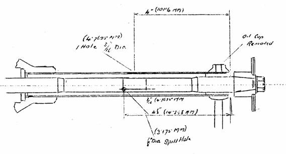
Figure 1. Dimensions for drilling fan support tube.
![]()
Example of a typical Service Bulletin.
PART XXIV – SERVICE BULLETINS
(A COLLECTION OF SERVICE BULLETINS ISSUED BY JOWETT CARS LIMITED)
The Jowett Car Club of Australia Incorporated is not responsible for any inaccuracies or changes that may occur within this document. Every effort has been made to ensure total accuracy. It is not a Jowett Car Club publication and, therefore, the Club has no control over its contents. These Technical Notes have been compiled by using the latest information available.
Compiled by Mike Allfrey.
January, 2007
INDEX FOR SERVICE BULLETINS
Bulletin Item No. and Description Page
001. Engineering Changes 3
002. Crankshaft Reconditioning Scheme 4
003. Control Box 4
004. Rear Timing Case Cover 5
005. Cooling System 5
006. Heating System – Frost Precautions 5
007. Heating System – Frost Precautions (Export) 5
008. Front Brakes 5
009. Air Vent Filter Felt (See Also Item 21) 6
010. Recommended Lubricants (See Also Items 32 and 74) 6
011. Spare Wheel Carrier 8
012. Upper Link Trunnion Pin 8
013. Water Transfer Seal 8
014. Water Pump Housing 9
015. Cylinder Liners and Pistons 9
016. Steering Track and Camber 9
017. Rear Hub Bearing Lubrication 11
018. Crankshaft – PB Models 12
019. Clutch Assemblies – PA and PB Models 12
020. Windscreen Wiper Blades 12
021. Air Vent Filter Felt (See Also Item 9) 13
022. Horn Relay 13
023. Camshaft 14
024. Gearbox Mounting 14
025. Front Engine Mounting – PB Models 15
026. Four Wheel Hydraulic Braking System 15
027. Front wheel Bearings 16
028. Connecting Rods – PB Models 17
029. Front Shock Absorbers 17
030. Steering Ball Joints (See Also Item 40) 18
031. Torque Wrench Settings (See Also Item 70) 19
032. Recommended Lubricants (See Also Items 10 and 71) 19
033. Introduction of 1951 Javelin – Summary of Alterations 19
034. Revised Tappet Assembly – Solid Type (See Also Item 38) 20
035. Lubrication – Use of Additives 21
036. LHS Crankcase – Connecting Rod Clearance 21
037. Adjustable Selector and Gear Change Links (RHD) 22
038. Revised Tappet Assembly (See Also Item 34) 23
039. Alteration to Specification – Javelin De Luxe Models 23
040. Steering Ball Housing Clearance – All Models (See Also Item 30) 23
041. Deletion of Steering Rod Cover – All Models (Part Number 50570) 24
042. Radiator Grille – PC Models 24
043. Exhaust System – PC Model 24
044. Fitting of Torsion Bars – All Models 24
045. Lubrication of Midship Bearing 24
046. Tow Bar Attachments 25
047. Air Filter – PA and PB Models 25
048. Steering Wheel – De Luxe Models 26
049. Hydraulic Tappet Extractor 26
050. Oil Pump Release Valve Spring 27
051. Engine Fade-out 28
052. Engine Internal Water Leaks – All Models 28
053. Sludge Release Holes – PC Models (See Also Item 71) 28
054. Shock Absorbers (Front) – PC Model 29
055. Fitting Spark Plug Shroud – PC Model 29
056. Wheel Brace Shortages – PC Model 29
057. Full Flow Oil Filter (Tecalemit) – PC Model 29
Bulletin Item No. and Description Page
058. Suppression Condenser – All Models 30
059. Oil Pump Filter Level – All Models 30
060. Lubrication Groove (Centre Main Bearing Housing) – PC Model 30
061. Overheating – PC Model 30
062. Steering Adjustment – All Models 31
063. Oil Return Pipe From Release Valve – Javelin and Jupiter 31
064. Camshaft Knock – Javelin and Jupiter 32
065. Water Pump Modification – PC Model 33
066. Gear Ratios – PC Model 33
067. Re-painting of Die Cast Radiator Grille – PC Model 34
068. Gearbox Extension Bearing Housing Washer – Javelin and Jupiter 34
069. Midship Bearing – All Models 34
070. Torque Wrench Settings – Javelin and Jupiter (See Also Item 31) 35
071. Connecting Rod Bearings – Javelin and Jupiter (See Also Item 53) 35
072. Throttle Rod Assembly 36
073. Timing Cover Oil Leak – Javelin and Jupiter 36
074. Recommended Lubricants – All Models (See Also Items 10 and 32) 37
075. Support Tube – Cylinder Head Gasket Support 38
076. Camshaft and Chain Wheel 38
077. Carburettors Zenith (30 VM) – Jupiter 39
078. Air Cleaners – Jupiter 39
079. Lubrication Grooves 39
080. Oil Filler Tube 39
081. Waterproofing Plug Lead Connections 39
082. Petrol System – Jupiter 39
083. Gearbox Selector Fork 3rd and 4th 40
084.Gear Change Stay 40
085. Water Pump and Fan 41
086. Flywheel Ring Gear 41
087. Gearbox Oil Capacity 41
088. Fitting Oil Cooler – Javelin (All Models) 42
089. Distributor Type DM2 44
090. Engine Internal Water Leaks and Gasket Failures 45
091. Petrol Pipe Assembly 46
092. Sludge Release Hole (See Also Items 53 and 71) 46
093. Lubrication of Fan Spindle Bearings 47
094. Gear Change Stay (See Also Item 84) 47
095. Crankshaft and Rear Main Bearing identification (See Also Item 2) 47
096. Front Suspension
097. Shock Absorbers, Armstrong Type
098. Radiator Improved Cooling – Jupiter
099. Locking of First Gear
100.
101.
102.
103. Crankcase Oil Galleries, Increased Flow
104. Crankshaft, Improved Design
105. Connecting Rods and Bearings
106.
107. Steering Wheel, Splined Fitting Type
108. Shock Absorbers, Woodhead Monroe Type
109. Chassis Height Setting
110. Improved Body Mounting – Jupiter
111. Fitting an Engine Sump Guard
112. Crankshaft, Improved Design
113. Cylinder Head Gasket Support
114.
115. Camshaft End Float
116. Oil Pump, Submerged
117. Lucas DM2 Distributor
118. Top Water Hose – Javelin
Bulletin Item No. and Description Page
119. Air Silencer Box – Javelin
120. Tecalemit Oil Filter, Change Interval
121.
122. Increased Loading of Synchromesh Springs
123. Swivel Pin Thrust Washers
124.
125.
126. Improved Sparking Plug Cover
127. Engine and Gearbox Oil Specification
128. Wheel Tracking
129. Gearbox Ratios – Javelin
130.
131. Tappet Adjustment, Solid Type
132. Sparking Plug Threads
133. Road Wheel Tracking
134. Bad Starting on Javelin and Jupiter Engines
135. Improvement to Reverse Selector Lock Lever
136. Identification of Replacement engines
137. Cylinder Head Studs
138. Method of identifying Series III Crankcases
139. Camshaft Conversion
140. Conversion of Suspension to Rubber Bushed Type
141. Balance Pipe Seal Test
142. Schedule of Labour Times
143. Gearbox Ratios
144. Improved Method of Sealing Oil Galleries
145.
146.
147.
148.
149. Cylinder Liner Bottom Seal
150.
151.
152.
153.
154. Modified Horn Pick Up Brush
155. Modified Reverse Lock Lever
156. Introduction of Jupiter Cylinder Heads on Javelin
157.
158. Changes in Shock Absorbers
159. Rear Axle Shaft Nuts (BSF to SAE Fine)
160.
161.
162. Front Spring Arm Conversion
163. Engine overheating and Pinking
164. Front Hub Bearing Conversion Scheme
165.
166. Camber Settings
167. Crankcase Breather Valve
Note: When using these Service Bulletins, care should be taken when identifying vehicles by engine number. It is very fortunate that Jowett Cars Limited used the same number for the Chassis Serial Number. For this reason, in situations where an engine will have been changed during the vehicle's life, the chassis Serial Number plate should be used for overall reference and identification purposes.
There are some gaps in the Service Bulletin Item Number sequence. Efforts are being made to trace the missing Service Bulletins. It must be appreciated that most of the Service Bulletins were issued over fifty years ago, therefore it has to be accepted that some may have gone missing.
Bulletin Issue Date – From March 1950
Item No. 1. Engineering Changes – All Javelin Models
Engineering Change Effective From
Flywheel and clutch assembly balanced as a unit. D8 PA 100
Exhaust manifold flanges increased in diameter. D8 PA 164
Redesigned Air Silencer. D8 PA 185
Hydraulic tappet fitted with end cover. D8 PA 781
Expansion chamber fitted to exhaust system. D8 PA 997
Carburettors changed from 30 VM4 to 30 VM5 (Type M). D8 PA 1753
Flywheel bolts, diameter increased from 3/8" to 7/16". D9 PA 2200
Dynamo changed from C45 to C39. D9 PA 2259
Connecting rod bolts, diameter increased from 5/16" to 3/8". D9 PA 2373
Spring arm trunnion bushes pressed on and retaining nuts deleted. D9 PA 2554
Steering box eccentric bush incorporated. D9 PA 2871
Exhaust system, single rear silencer. D9 PA 3138
12 Volt single battery fitted. D9 PA 3696
Copper lead connecting rod bearings fitted. D9 PA 3794
Fitting of starter solenoid and electrical harness alterations (RHD). D9 PA 4243
Copper lead front and centre main bearings fitted. D9 PA 4322
Oil bath air filter fitted, export only. D9 PA 4431
Oil bath air filter fitted, all models. D9 PA 5374
Modified water pump (T/C 26). D9 PA 5857
Vacrom piston rings fitted (T/C 27). D9 PA 5756
Front suspension lubrication – revised method (T/C 27). D9 PB 5979
Adjustable steering balls fitted (RHD). D9 PB 6572
Adjustable steering balls fitted (all models). E0 PB 6801
Exhaust system, introduction of detachable tail pipe. E0 PB 7509
Redesigned rear timing cover. E0 PB 7676
Introduction of detachable exhaust tail pipe E0 PB 8276
Trico windshield wiper blades fitted. E0 PB 8276
New type steering link fitted – 'H' section stamping. E0 PB 8313
Oil cup added to water pump housing. E0 PB 8472
Small end bearing changed from 'Glacier' to 'Clevite' metal. E0 PB 8737
Introduction of strengthened cylinder liners and barrel ground pistons. E0 PB 8825
Hardened crankshaft fitted (RHD). E0 PB 8902
Hardened crankshaft fitted (LHD). E0 PB 8937
Horn relay fitted to horn circuit. E0 PB 9293
Oil filter outer casing strengthened. E0 PB 9423
Main bearing dowel drilled. E0 PB 9540
Oil delivery pipe union bolt wired for locking purposes. E0 PB 9860
New type lower fixing arrangement for front shock absorbers. E0 PB 9877
Steel sump tray assembly. E0 PB 9878
Reinforced front engine mountings (vertical stay deleted). E0 PB 10450
Introduction of serrated type connecting rods. E0 PB 10506
Introduction of four-wheel hydraulic braking system. E0 PB 10594
Redesigned steering ball joints. E0 PB 10789
1951 Javelin commences from. E0 PC 11326
Solid type tappet fitted. E0 PC 11907
Adjustable selector and gear change links fitted. E0 PC 12340
'Clear vision' steering wheel fitted (Deluxe). E0 PC 13111D
Maximum oil pressure increased. E1 PC 15098
Rubber bonded exhaust mounting fitted. E1 PC 15432
Radiator grille redesigned. E1 PC 15631
Front shock absorber strength increased. E1 PC 16500
Tecalemit oil filter introduced. E1 PC 16603
Oil groove added to crankcase main bearing bore. E1 PC 16744
Sludge release hole drilled in connecting rod cap. E1 PC 17402
New cylinder head gasket support tube and distance washer introduced. E1 PC 17900
Water pump and fan improved. E1 PC 18140
Gearbox extension bearing washer strengthened E1 PC 18141
Throttle rod modified. E1 PC 18550
Engineering Change Effective From
Hole deleted from rod half of connecting rod bearing. E1 PC 18646
Return pipe from oil pressure relief valve added. E1 PC 18985
Camshaft chainwheel modified (Vernier timing adjustment). E1 PD 19295
Water proof plug lead connections fitted. E1 PD 19760
Gear change stay fitted. E1 PD 20135
Gear change stay modified. E2 PD 20144
Non-stick taper introduced on water pump spindle. E2 PD 20379
Positive locking for first gear introduced. E2 PD 20641
Splined steering wheel fitted (Deluxe). E2 PD 20881D
Connecting rod cap sludge release hole deleted. E2 PD 20977
Lucas DM2 distributor fitted. E2 PD 21016
Main beam warning light fitted (Standard). E2 PD 21035
AC petrol filter introduced. E2 PD 21147
Splined steering wheel fitted (Standard). E2 PD 21838
Armstrong shock absorbers fitted. E2 PD 21868
Rubber bushed front suspension introduced. E2 PD 21868
Crankcase oil flow increased. E2 PD 21937
Increased flow oil cooler fitted. E2 PD 21937
Redesigned crankcase fitted. E2 PD 22190
Series III engine introduced. E2 PD 22221
Woodhead-Monroe shock absorbers fitted. E2 PE 22346
Narrow lock-notch connecting rods fitted. E2 PE 22451
Top water hose adaptor assembly fitted. E2 PE 22560
Main beam warning light fitted (Deluxe). E2 PE 22739D
Crankshaft tolerances revised. E2 PE 22873
Loading on synchromesh springs increased. E2 PE 23106
Submerged oil pump fitted. E2 PE 23122
One-piece cylinder head gasket support and liner retaining flange fitted. E2 PE 23184
Battery mounting improved. E2 PE 23257
Air silencer box modified. E2 PE 23320
Adjustable camshaft peg fitted. E2 PE 23643
Sparking plug covers improved. E2 PE 24036
Wide ratio gearbox re-introduced. E3 PE 24179
Notes:
Oil cooler first fitted to Javelins after 7th January, 1952.
Cylinder head studs modified from crankcase set number 26496.
Improved oil gallery plugs from crankcase set number 26496.
Bulletin Issue Date – From 1950
Item No. 1a. Engineering Changes – Jupiter Models
Engineering Change Effective From
Body side strakes deleted. E0 SA 41
Introduction of four-wheel hydraulic braking system. E0 SA 56
Salisbury 3HA rear axle introduced. E0 SA 56
Louvres added to bonnet for improved cooling while car is stationary. E1 SA 165
New cylinder head gasket support tube and distance washer introduced. E1 SA 270
Throttle rod modified. E1 SA 270
Gearbox extension bearing washer strengthened. E1 SA 284
Hole deleted from rod half of connecting rod bearing. E1 SA 423
Petrol pump relocated from firewall to chassis RHS. E1 SA 439
Radiator cooling area increased (LHD). E2 SAL 458
Return pipe from oil pressure relief valve added. E1 SA 480
Camshaft chainwheel modified (Vernier timing adjustment). E1 SA 481
Shorter oil filler tube introduced. E1 SA 504
Water proof plug lead connections and rubber distributor cover fitted. E1 SA 520
Non-stick taper introduced on water pump spindle. E2 SA 575
AC Air filters fitted. E2 SA 590
Oil cooler mounted on engine front RHS. E2 SA 631
Engineering Change Effective From
Positive locking for first gear introduced. E2 SA 657
Carburettors, Zenith 30VM introduced. E2 SA 657
Connecting rod cap sludge release hole deleted. E2 SA 692
Radiator cooling area increased. E2 SA 695
Lucas DM2 distributor fitted. E2 SA 717
Steering column universal joint changed to Hardy Spicer type. E2 SA 730
Rubber bushed front suspension introduced. E2 SA 865
Armstrong shock absorbers introduced. E2 SA 865
Series III engine introduced. Oil flow through oil cooler increased. E2 SA 882
Armstrong shock absorbers replaced by Woodhead-Monroe competition units. E2 SA 921
Narrow lock-notch connecting rods fitted. E2 SA 938
Cross-bracing added between scuttle and chassis. E2 SA 940
Mk 1a Jupiter introduced. E2 SC 940
New crankshaft and connecting rods introduced with revised tolerances introduced. E2 SC 942
Steering rack housing mounted on lugs, instead of spigot. E2 SC 942
Submerged oil pump introduced. E2 SC 945
Increased loading added to synchromesh rings. E2 SC 945
One-piece cylinder head gasket support and liner retaining flange fitted. E2 SC 948
Adjustable camshaft peg fitted. E2 SC 957
Synthetic rubber cylinder liner seals introduced from crankcase set number 26574.
Note on Jupiter Engineering Changes:
These Engineering Changes should be read (used) in conjunction with the preceding Javelin Engineering Changes for those components that are shared by the two vehicle types.
DISCLAIMER:
IT SHOULD BE NOTED THAT, WHERE A BULLETIN STATES THAT A PART IS 'AVAILABLE' – THIS MAY NOT NECESSARILY BE SO. THE BULLETINS WERE ISSUED BY JOWETT CARS LIMITED IN THE EARLY 1950S AND ARE REPRINTED HERE FOR REFERENCE ONLY.
Bulletin Issue Date: March 1950
Item No. 2. Crankshaft Reconditioning Scheme
Our Spares Department are now in a position to supply reconditioned crankshafts complete with bearings, which will be taped into position.
Crankshaft journals will be ground to the following undersizes:
Connecting Rod Journals: Minus 0.010" (0.25 mm); 0.020" (0.51 mm); 0.030" (0.76 mm); 0.040" (1.02 mm).
Note: In cases where it is necessary to regrind the side faces of the journal, the width will be increased to nominal + 0.025" (0.52 mm) and oversize connecting rods provided. (See section on connecting rods)
Main bearing Journals: Minus 0.005" (0.13 mm); 0.010" (0.25 mm); 0.20" (0.51 mm).
Identification:
A series of numbers will be stamped on the crank web giving details of the undersizes of the journals, together with the part number. Example: A crankshaft with 0.010" (0.25 mm) undersize connecting rod journal and a 0.020" (0.51 mm) undersize main bearing journal will be designated – R50647/10/20.
With a 0.030" (0.76 mm) undersize connecting rod journal and 0.010 (0.25 mm) undersize main bearing journal will be designated – R50467/30/10 and similarly for any other form of undersizes.
In addition to the above if the connecting rod journal width has been increased the identification key will be followed by '/0'.
The following undersize bearings are available from our Spares Department. The part number will be retained for the standard size bearings, with a suffix dependant on the bearing undersize.
Connecting Rod Bearings:
Undersize 0.010" (0.25 mm) Part Number 52574/10/– (Current Part Number J54710-B)
Undersize 0.020" (0.51 mm) Part Number 52574/20/– (Current Part Number J54710-C)
Undersize 0.030" (0.76 mm) Part Number 52574/30/– (Current Part Number J54710-D)
Undersize 0.040" (1.02 mm) Part Number 52574/40/– (Current Part Number J54710-E)
Undersize 0.050" (1.27 mm) Part Number 52574/50/– (Current Part Number J54710-F)
Undersize 0.060" (1.524 mm) Part Number 52574/60/– (Current Part Number J54710-G)
Main Bearing (Front and Centre):
Undersize 0.005" (0.13 mm) Part Number 52573/5/– (Current Part Number Not Stocked)
Undersize 0.010" (0.25 mm) Part Number 52573/10/– (Current Part Number 52573-B)
Undersize 0.020" (0.51 mm) Part Number 52573/20/– (Current Part Number 52573-C)
Undersize 0.030" (0.76 mm) Part Number 52573/30/– (Current Part Number 52573-D)
Undersize 0.040" (1.02 mm) Part Number 52573/40/– (Current Part Number 52573-E)
Undersize 0.050" (1.27 mm) Part Number 52573/50/– (Current Part Number 52573-F)
Main Bearing (Rear):
Undersize 0.005" (0.13 mm) Part Number 50646/5/– (Current Part Number Not Stocked)
Undersize 0.050" (1.27 mm) Part Number 50646/10/– (Current Part Number 50646-B)
Undersize 0.050" (1.27 mm) Part Number 50646/20/– (Current Part Number 50646-C)
Undersize 0.050" (1.27 mm) Part Number 50646/30/– (Current Part Number 50646-D)
Undersize 0.050" (1.27 mm) Part Number 50646/40/– (Current Part Number 50646-E)
Undersize 0.050" (1.27 mm) Part Number 50646/50/– (Current Part Number 50646-F)
Connecting Rods:
Oversize connecting rods are available for fitting to crankshafts where the connecting rod journal width has been increased by 0.025" (0.52 mm), and will normally be supplied with the crankshaft. Oversize connecting rods will be identified by Part Number 50651/0 stamped on the connecting rod and will be painted RED with oil resisting enamel. Refer to Spares Note Number 24 for parts changes.
Bulletin Issue Date: March 1950
Item No. 3. Control Box
Investigation has shown the possibility of a very high voltage being developed by the generator, with subsequent damage to the control box if it is not effectively earthed. On the Javelin the control box is earthed through a wire which is secured under a clip retaining the main body electrical harness to the toe-board (PB Parts List Item Number 1281) on the LHS of the car.
Special attention has been given to this point during assembly, and we suggest that when cars are in your workshops for servicing, the opportunity should be taken to ensure there is a good connection between the earthing wire and the toe-board.
Bulletin Issue Date: March 1950
Item No. 4. Rear Timing Case Cover
A redesigned rear timing case cover, Part Number 50690 (Item Number 19), has been fitted to all Javelin cars from Engine Number E0 PB 7676. The new type cover which is interchangeable with the original cover, has been redesigned to retain oil in the oil filter and accessories when the engine is stationary.
Bulletin Issue Date: March 1950
Item No. 5. Cooling System
Agents will of course be aware that with a pressurised cooling system it is essential that the radiator cap is removed when draining, in order to ensure that the system is completely empty.
Some owners may not, however, be aware of this and we would therefore strongly recommend that you emphasise to such owners the importance of carrying out the following drill when draining:
1. Remove the radiator cap.
2. Open drain taps under cylinder heads and check that water is flowing freely.
3. As soon as all water is drained from the cooling system, run the engine for NOT more than 10 seconds.
Bulletin Issue Date: March 1950
Item No. 6. Heating System – Frost precautions (Home Market)
Damage may be experienced to the heating system on Javelin cars as a result of freezing. It will be readily understood that it is impossible for the heater circuit to be drained, and this must therefore be protected against exceptionally low temperatures. A label will be secured to the heater control tap giving this information.
Javelin owners should be advised to have the cooling system of their cars treated with an inhibited anti-freeze solution, if frost conditions are likely to be experienced. Using Bluecol anti-freeze the correct proportion for protection against 35° of frost is 3½ pints (1.988 litres) of anti-freeze to 12½ pints (7.103 litres) of water.
Bulletin Issue Date: March 1950
Item No. 7. Heating System – Frost Precaution (Export)
Cars are now being shipped from the factory with the heater circuit disconnected to avoid the possibility of frost damage in transit. The inlet and outlet hoses will not be fitted, but placed in the tool compartment. The following action must be taken to connect the heating system before delivery of the car to the owner.
1. Drain the cooling system.
2. Unsolder the blanking cap from the radiator inlet pipe situated at the lower left hand corner of the radiator,
3. Fit the long hose (2' 9") (838.2 mm) between the LHS tube of the heater and the control cock fitted to the water pump.
4. Fit the short hose (2' 2") (711.2 mm) between the RHS tube of the heater and the inlet tube of the radiator.
5. Refill the cooling system with an inhibited anti-freeze solution in the proportions shown at Item 6.
Bulletin Issue Date: March 1950
Item No. 8. Front Brakes
'Grabbing' or 'judder' on the front brakes may be caused by the following:
1. Incorrect adjustment, allowing excessive clearance between the brake lining and drum.
2. Brake linings insecurely or incorrectly riveted to the shoes.
3. Brake shoe pivot pin loose on the back plate.
4. Irregularities in the surface of the brake drum bore.
It is possible that even with the above points correct, grabbing may occur, and in this case the existing linings should be replaced with Mintex M14J linings.
Bulletin Issue Date: March 1950
Item No. 9. Air Vent Filter Felt
(PB List, Item 27, Part Number 52244)
If the tappet cover air vent filter felts are not cleaned or replaced at approximately 10,000 miles (16,000 km) or more frequently if necessary, there is a danger of them becoming blocked causing excessive crankcase depression. Owners should, therefore, be advised to have this service carried out. With the air vents blocked this depression is likely to be so great that the operation of the petrol pump diaphragm is neutralised causing the engine to 'fade out'.
Maximum depression occurs at approximately 2,500 RPM (40 mph – 64 kph) at which speed it should not exceed approximately ¾" (19 mm) lift using a mercury gauge or 10" (205 mm) using a water gauge. A copper pipe sweated into a spare oil filler cap can conveniently be used when coupling the depression gauge to the crankcase.
Bulletin Issue Date: March 1950
Item No. 10. Recommended Lubricants
When servicing Javelin Cars please advise owners that the following lubrication recommendations supersede those shown in their PA and PB Instruction Books:
Engine – 20 °F to 70 °F
Wakefield Castrol XL
Anglo Essolube 30
Prices Energol SAE 30
Shell X100 SAE 30 or Double Shell
Vacuum Mobiloil A
Duckhams Adcol NP.30
Engine – Over 70 °F
Wakefield Castrol XXL
Anglo Essolube 40
Prices Energol 40
Shell X100 SAE 40 or Triple Shell
Vacuum Mobiloil BB
Duckhams Adcol NP.40
Gearbox – 20 °F to 70 °F
Wakefield Castrol XL
Anglo Essolube 30
Prices Energol SAE 30
Shell X100 SAE 30 or Double Shell
Vacuum Mobiloil A
Duckhams Adcol NP.30
Gearbox – Over 70 °F
Wakefield Castrol XXL
Anglo Essolube 40
Prices Energol 40
Shell X100 SAE 40 or Triple Shell
Vacuum Mobiloil BB
Duckhams Adcol NP.40
Rear Axle – Over 20 °F
Wakefield Castrol XL
Anglo Essolube 30
Prices Energol SAE 30
Shell X100 SAE 30 or Double Shell
Vacuum Mobiloil A
Duckhams Adcol NP.30
Item No. 10. Recommended Lubricants (Continued)
Steering Box, Propeller Shaft Centre Bearing, Chassis Lubricating Points
Wakefield Castrolease Medium
Anglo Esso Grease
Prices Belmoline
Shell Retinax G
Vacuum Mobil-grease No. 4
Duckhams Adcol HPG
Suspension Reservoirs
Wakefield Castrol XXL
Anglo Essolube 40
Prices Energol 40
Shell X100 SAE 40 or Triple Shell
Vacuum Mobiloil BB
Duckhams Adcol NP.40
Grease for Wheel Hubs, Water Pump Etc.
Wakefield Castrolease Heavy
Anglo Esso Grease
Prices Belmoline C
Shell Retinax RB Grease
Vacuum Mobil-grease No. 4
Duckhams Adcol HBB
Brake Cables
Wakefield Castrol Brake Cable Grease
Anglo Esso Graphite Grease
Prices Rangraphine
Vacuum Mobiloil Graphited Grease
Duckhams ZMQLKG 16
Brake Fluid
Girling Crimson Brake Fluid
General Lubrication – Fan Spindle, Door Hinges Etc.
Wakefield Castrol XL
Anglo Essolube 30
Prices Energol SAE 30
Shell X100 SAE 30 or Double Shell
Vacuum Mobiloil A
Duckhams Adcol NP.30
NOTE: The Shell X100 range of oils are available only in certain overseas territories.
Bulletin Issue Date: March 1950
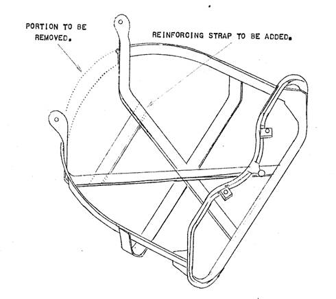
Item No. 11. Spare Wheel Carrier (Standard Model PB)
Under certain conditions there is a possibility that the spare wheel carrier will foul the rear brake compensator. From Javelin Serial Number E0 PB 8145 the rear portion has been removed and a reinforcing strap has been substituted.
Should this condition be experienced on cars before E0 PB 8145, the carrier may be modified as shown in the sketch below:
Bulletin Issue Date: April 1950
Item No. 12. Upper Link Trunnion Pin
The new type upper link pin, Part Number 52716, which is reduced in length, is fitted to cars where the upper link pin is lubricated by a greaser. The old type pin, Part Number 50301, should be used where the lubrication is by oil feed. Refer to Technical Circular Number 27 and Spares Note Number 26 for further details.
Bulletin Issue Date: April 1950
Item No. 13. Water Transfer Seal
Please note that the composition of the water transfer seal has recently been changed from rubber to heat resisting neoprene. The new type seals, Part Number 52708, should be used in all cases when replacing water transfer seals.
The original seal, Part Number 50496, was interchangeable with the suspension upper link trunnion seal, also Part Number 50496, and stocks should be retained for this purpose. The new type seal, Part Number 52708, should not be used for the front suspension assemblies.
Refer to Spare Parts Note Number 27 for parts change information.
Bulletin Issue Date: April 1950
Item No. 14. Water Pump Housing
From Engine Number E0 PB 8472 an oil cup has been fitted to the rear of the water pump housing extension tube to assist the lubrication of the fan bearing.
Refer to Spares Note Number 28 for parts change information.
Bulletin Issue Date: April 1950
Item No. 15. Cylinder Liners and Pistons
From Engine Number E0 PB 8345 a new type of cylinder liner, Part Number 54019, has been fitted. This liner can be identified by the fact that the flange which locates with the crankcase set (50522/3) is larger than on the original type, Part Number 50642. A new type piston, Part Number 50656BG, and second compression ring, Part Number 54021, have also been introduced for use with this liner. The piston has the letters 'BG' stamped on the crown and the second compression ring has an internal step which should be fitted as shown in the illustration below:
As a result of these changes, the length of the locating plate distance tube which fits on the centre cylinder head stud has been reduced by 1/16" (1.587 mm) to 2 7/32" (56.355 mm). Should the shorter distance tube be used with the old type cylinder liners, a 1/16" (1.587 mm) brass washer should be fitted between the tube and the locating plate to ensure the tube is nipped by the cylinder head.
Liners and pistons are fully interchangeable in sets, but stocks of the old type liners and pistons will be maintained.
Refer to Spares Note Number 30 for parts change.
Bulletin Issue Date: June 1950
Item No. 16. Steering Track and Camber
Camber angle and track should invariably be checked together as the track cannot be checked effectively before camber is checked, and if necessary re-set. The following routine is the only satisfactory method of carrying out these checks and we would emphasize the fact, that short cuts should be avoided.
1. Check wheel bearings, upper links, lower links, stub axles and wheel rims for damage, wear etc., and rectify as found necessary. In addition, when checking the track, it is essential that the following points are checked for play and, if necessary, adjusted – a) steering cone nuts and steering rods should move freely in the steering link assembly without any play; – b) the lift between the swivel pin and the stub axle should not exceed 0.008" (0.20 mm).
2. Slack off the torsion bar adjusters completely.
3. Set the car level. To do this, jack up the front of the chassis, using a screw type jack under each frame side member at the gearbox cross member, so that the underside is approximately 10" (255 mm) from the ground. This distance will, of course, be governed by the adjustment necessary to level the car transversely. The frame level gauge is illustrated in Service Aid Number 6, and is essential for this purpose.
4. With the use of screw type jacks, raise the front spring arms until they are horizontal. The front wheels should now be clear of the ground.
5. Check the camber angle, which should be zero, with the suspension in this position, and the wheels 'straight ahead'. The maximum tolerance permissible is:
Vertical – Minus 1/8" (3.175 mm) or;
Zero – Minus 0° – 27'.
Item No. 16. Steering Track and Camber (Continued)
6. Camber angle may be re-set by adding or removing shims behind the upper link bracket. As a general guide it can be taken that removing or adding 1/8" (3.175 mm), thickness of shims alters the camber angle by 5/32" (0° – 35').
7. Remove
all jacks by lifting with a garage jack under the centre of the gearbox cross
member. Lower the chassis until, with the wheels on the ground, the front
spring arms are horizontal. Set the track dead parallel.
Special note: It is essential that the steering rod assemblies are within
3/16" (4.50 mm) of equal length. This length may be measured between
the inner face of the steering ball joints, and the face of the steering ball
socket. If this point is not given careful attention the steering
assembly will be strained on an extreme lock; also 'kick' on the steering wheel
may be experienced.
8. Lock the steering box with the wheels straight ahead. It is essential that the straight position is maintained during the whole of the check, the steering must therefore be locked by some method such as inserting a wooden wedge between the steering box case and the steering box arm.
When doing this special care should be taken to avoid damage to the steering box casing.
9. Raise the car until the wheels are clear of the ground and remove the front road wheels. Fit the independent tracking equipment as detailed in Service Aid Number 6, in the following manner. Remove the grease nipple from the bottom of the swivel pin boss, and thoroughly clean the boss. Fit the pointer and secure with a 1/8" gas setscrew, screwed into the greaser threaded drilling.
Care should be taken to avoid distorting the pointer by over tightening the setscrew.
10. Fit the calibrated arm to the brake drum and secure with wheel nuts. Tighten the brake adjuster so that the drum is locked and the plate in line with the pointer arm. Set the pointer on the centre mark of the calibrated plate with the spring arm horizontal.
11. Raise the spring arm until the suspension is at maximum bump position (i.e. until the full weight of the car is resting on the front wheel buffer). Check the pointer reading in this position.
12. Lower the spring arm until it is resting hard against the rebound buffer on the frame-side, and again note the reading. The maximum difference in readings on the calibrated plate must not exceed 1/32" (0.79 mm). The ideal of course is to have no track variation at all and this should be achieved wherever possible.
Note: 1/32" reading on the plate represents a difference of 1/16" on each wheel, which in turn represents 1/8" difference in track.
Should these limits be exceeded it will be necessary to alter the height of the steering ball, either by replacement if the ball joints are the fixed type, or by screwing as necessary, if the balls are adjustable. For cars with fixed type joints, the following steering balls to correct track variations, can be supplied, assembled into steering ball joint assemblies:
Standard 25/32" Shank Height
Plus 5/32" = 15/16" Shank Height
Plus ¼" = 33/32" Shank Height
The following will be found a useful general guide when correcting excessive track variations:
Steering Ball too Short:
A) 'Toe-in' at rebound.
B) 'Toe-out' at bump.
C) Combination of conditions A) and B).
Steering Ball too High:
D) 'Toe-out' at rebound.
E) 'Toe-in' at bump.
F) Combination of conditions D) and E).
After checking, and if necessary correcting on one side, the operation should be repeated on the other side.
13. Finally, re-set the torsion rods, re-fit the greasers and road wheels, remove the wooden block from the steering box, re-adjust the front brakes, and re-check the overall track. The track setting should be parallel to 1/16" toe-out.
Item No. 16. Steering Track and Camber (Continued)
14. MOST IMPORTANT!
After the chassis height has been re-set and with the spring arm resting hard against the rebound buffer on the frame-side, check the distance between the steering ball housing and the steering arm, which must not under any circumstances be less than 1/16" as shown in the sketch below.
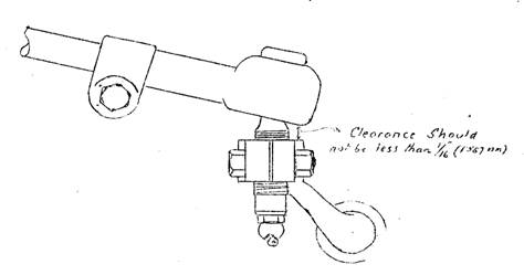
It should be noted that steering arms, Part Numbers 52667 (RHS) and 52666 (LHS), are fitted to Right Hand Drive cars and steering arms, Part Numbers 52678 (LHS) and 52679 (RHS), are fitted to Left Hand drive cars. The difference in the right and left hand drive models is in the height of the forward end of the steering arm in relation to the stub axle, and therefore it will be readily understood that the fitting of the incorrect arm will seriously affect the steering geometry.
Bulletin Issue Date: June 1950
Item No. 17. Rear Hub Bearing Lubrication
Cases have been reported where an over application of grease to the rear hubs has resulted in brake lining contamination and subsequent brake inefficiency. A 3/16" (4.7625 mm) diameter grease relief hole will shortly be incorporated for all rear hub bearings at the rear and outer (hub) end of the axle casing tubes, as shown in the sketches below:
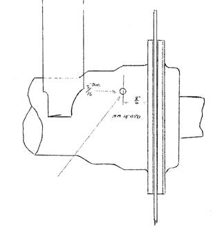
Figure 1. Location of grease release hole.
Item No. 17. Rear Hub Bearing Lubrication (Continued)
When greasing rear hubs embodying this feature, hubs should be lubricated until grease just appears from the relief hole.
Side elevation sketch below:
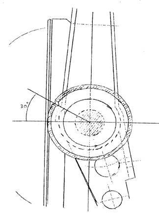
Figure 2. Section through rear axle tube, showing angle of grease hole.
Bulletin Issue Date: June 1950
Item No. 18. Crankshaft – PB Models
(Item 113 in Parts List, Part Number 52010)
Crankshafts with hardened main and connecting rod bearing journals and modified oil drillings have been fitted to all Javelin cars with effect from Engine Number E0 PB 8937 (LHD) and E0 PB 8902 (RHD). Copper-lead main bearing shells, Part Number 52573 and 50646, and connecting rod shells, Part Number 52574, will be fitted with this crankshaft.
Bulletin Issue Date: June 1950
Item No. 19. Clutch Assemblies – Borg & Beck, PA and PB Models
All replacement clutch cover and pressure plate assemblies, Part Numbers 50844 (RHD) and 52420 (LHD), are now treated with 'Lanoline' as a precaution against corrosion. When replacing clutch assemblies it is most important that all traces of the Lanoline are removed, before assembly.
This will apply to replacement clutch assemblies, Part Number AS6622, for Bradford CC Models.
Bulletin Issue Date: June 1950
Item No. 20. Windscreen Wiper Blade – PB Models
A re-designed windscreen wiper blade, Part Number 54048, has been fitted to all Javelin cars from Engine Number E0 PB 8276. The new type blade is fully interchangeable with the original blade. Refer to Spares Note Number 44 for parts change information.
Bulletin Issue Date: September 1950
Item No. 21. Air Vent Filter Felt (Item 27, Part Number 52244)
SPECIAL ATTENTION!
Further to Service Bulletin Item Number 9.
Attention is again drawn to the possibility of engine 'fade-out', if the tappet cover air vent filter felts become blocked. It is most important that the filter vents are renewed at the recommended periods. In many cases of engine failure, from many reports being received it would appear that extensive tests are being carried out to the fuel and ignition systems without satisfactory and conclusive results. It will be readily appreciated that the air vents control the entry of air into the crankcase to replace that which is withdrawn through the breather valve, therefore if the felt vents are blocked the crankcase depression will increase and subsequently neutralise the operation of the petrol pump diaphragm.
Maximum depression occurs at approximately 2,500 rpm (40 mph or, 64 kph) and when testing for this particular fault the car should be driven at light throttle openings at approximately the above speeds, and not at high speeds as for other complaints, such as normal 'drying up' and 'pre-ignition'. Replacements are inexpensive and quickly fitted and it is therefore suggested that the felts are replaced at all times when there is the slightest suspicion of restriction. It will be understood that cleaning the tappet covers, or the complete engine unit, will in most cases allow the felts to become blocked with dirt, they should therefore be replaced after cleaning operations.
For test purposes or in an emergency the engine may be run without the felts for a limited period.
Bulletin Issue Date: September 1950
Item No. 22. Horn Relay
A Lucas type SB.40 relay, Part Number 54025, has been incorporated in the horn wiring circuit on all Javelin cars, with effect from Engine Number E0 PB 9293.
The relay may be fitted to previous models as detailed below:
1. Fit the relay to the scuttle dash, immediately below the control box, with two 6 x ½" self tapping screws, Part Number ND-1578.
2. Disconnect the battery, and transfer the horn leads from terminal A2 on the control box to C1 on the relay (identification colour – purple).
3. Disconnect the two wires (identification colour – purple with black) from the 'push-in' connector behind the instrument panel, and from the terminals inside the horns.
4. Extend the horn push lead (identification colour – purple and black) from the connector to the W terminal on the relay.
5. Fit a new lead from the main battery lead on the starter solenoid to the C2 terminal on the relay.
6. Fit a short earth lead from each horn terminal (which was originally fitted with a purple and black lead) to one of the horn securing bolts
Please refer to the wiring diagram on the next page.
Item No. 22. Horn Relay (Continued)
Wiring Diagram for Fitting Of Horn Relay:
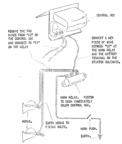
Figure 1. Horn relay wiring diagram.
Bulletin Issue Date: September 1950
Item No. 23. Camshaft
To avoid the possibility of the operating cams of the camshaft fouling adjacent tappet assemblies, the width of the operating cams has been reduced from ½" (12.7 mm) to 7/16" (11.11 mm) with effect from Javelin car Engine Number E0 PB 9332.
Bulletin Issue Date: September 1950
Item No. 24. Gearbox Mounting
Investigation has shown the possibility of serious damage to the gearbox casting and the clutch housing, if the gearbox to clutch housing nuts are not secure. A tightness check should be carried out during the 2,000 mile (3,200 km) service and subsequently at intervals of approximately 5,000 miles (8,000 km).
Bulletin Issue Date: September 1950
Item No. 25. Front Engine Mounting – PB Models
A reinforced front engine mounting which may be identified by a central reinforcing plate bonded through the centre of the rubber portion of the mounting has been fitted to all Javelin cars with effect from Engine Number E0 PB 10450. With the introduction of this mounting, the timing case to frame vertical stay, Item Number322, Part Number 50930, is no longer fitted.
The two assemblies are fully interchangeable, and when fitting the new type mounting to cars prior to E0 PB 10450, the frame vertical stay may be removed.
Refer to Spares Note Number 50 for parts change information.
Bulletin Issue Date: September 1950
Item No. 26. Four Wheel Hydraulic Braking System
Introduced with effect from Javelin car Engine Number E0 PB 10594.
Description:
The brakes fitted are Girling 9" x 1¾" (228.6 mm x 44.45 mm) hydraulic leading sliding shoe on the front and Girling 9" x 1¾" (228.6 mm x 44.45 mm) non servo sliding shoe with internal hand-brake mechanism on the rear. Foot brake application is hydraulic with a separate mechanical operation for the hand or parking brake.
Front Brakes:
The front brakes are 9" x 1¾" (228.6 mm x 44.45 mm) hydraulic leading shoe system, each shoe is operated by a separate wheel cylinder located on the back plate. It will be seen that each shoe is located on one cylinder and expanded by the piston of the other, with the leading edges of both shoes making initial contact with the drum. The rear of the cylinder casting is formed to create a 28° inclined faced abutment with a steel strip which is the locating slot for the trailing edge, thus increased efficiency and more even lining wear is obtained owing to the sliding action of the shoes. Each brake shoe is held in position by a return spring which passes from the abutment end of the shoe to a hole in the back plate, and the springs are not positioned from shoe to shoe.
Adjustment for lining wear is provided by knurled snail cam adjusters which operate against a peg at the actuating end of the shoes, the adjusters turn clockwise to expand the shoes.
Each wheel cylinder, the bodies of which are made from alloy, consist of a seal retaining spring, a bakelite seal spreader, seal and piston. The two wheel cylinders are interconnected by a bridge pipe which passes from cylinder to cylinder on the reverse side of the back plate, provision being made for a bleed valve on one cylinder only. It will be noted that the flexible feed pipe is now connected to the wheel cylinder at the rear and not as previously at the top.
Front Brake Adjustment:
1. Jack up the car until the front wheels are clear of the ground.
2. Rotate the wheels and if necessary, operate the adjusting bolts anti-clockwise until the wheels rotate freely, and without drag.
3. Turn one of the adjuster bolts until its brake shoe contacts the brake drum and release the adjuster until the shoe is just free.
4. Repeat the procedure for the second adjuster and the other wheel.
5. Apply the foot brake and after a short pause re check the wheels for free rotation. It is obviously essential that the shoes should not be in contact with the brake drum when the brake pedal is in the off position.
Rear Brakes:
The rear brakes are 9" x 1¾" (228.6 mm x 44.45 mm) hydraulic non servo sliding shoe. The shoes are hydraulically operated by a hydraulic wheel cylinder which consists of a die cast aluminium housing, two plungers complete with dust covers, two seals, two bakelite seal retainers and a seal retaining spring. The hand-brake expander housing, which is part of the wheel cylinder casting, consists of a hardened steel wedge which also acts as the draw link, two hardened steel rollers and two flat inclined faced hardened steel tappets. The retaining cover, which is secured on the housing by four set screws, has two tabs; these prevent the flat tappets from sliding out of the housing when the brake shoes are removed. A bleeder valve is also incorporated in the cylinder housing, a rubber cover being fitted to exclude dust etc.
The shoes are located at the adjustment end, in the slots provided in the adjuster plungers, being held in position by two springs from shoe to shoe, the shorter of the two being fitted at the adjuster end of the shoes. It will be seen that the shoes are not anchored in any fixed position but are allowed to slide both at the hydraulic pistons and the adjuster links.
Item No. 26. Four Wheel Hydraulic Braking System (Continued)
Adjustment for lining wear is made by the screwed adjuster wedge as for the previous mechanical rear brake operation. The adjuster clicks over notches as it is tightened in a clockwise direction: do this as far as it will go without forcing until the shoes are binding on the brake drum. Then slacken off the adjusting screw until the drum revolves without binding on the brake shoes, releasing for two notches is normally sufficient.
Hand-brake Operation:
The hand-brake cable is no longer inter-connected with the foot brake mechanism, a pull rod is inserted between the hand-brake and rear brake cables which gives a direct connection between the hand-brake lever and the rear brake compensator. Adjustment is provided at each end of the pull rod and as with the previous system there should be a slight play in the linkage before movement of the hand-brake lever operates the rear shoes. With the rear brake shoes correctly adjusted the hand brake should be full on at approximately 5 notches.
Master Cylinder:
This is the Girling tension type master cylinder and is operated between a pivot mounted on a bracket fixed to the chassis side member and a short connecting link from the brake pedal. The draw rod is protected from dirt and dust by a rubber boot which should be packed with 'Wakefield Rubber Grease No. 3'. Unlike the hydraulic-mechanical system previously used, there is no movement of the main body of the master cylinder and the flexible hose to the distribution block has been replaced by a short copper pipe.
Bleeding the Hydraulic System:
Further to the usual procedure when carrying out this work, the following points should receive particular attention:
1. Before commencing operations adjust the brakes, so that there will be no danger of the brake shoe flexing and thereby allowing air to enter the system.
2. Each wheel should be bled in a definite order beginning at the wheel nearest to the master cylinder. The last of the four wheels to be bled will therefore be the rear near-side wheel (LHS) on a RHD Javelin (and RHS for a LHD car).
3. The type of brake fluid recommended is Girling 'Crimson' and when topping up the supply tank during bleeding operations fluid which has circulated through the system should not be used, due to its probable aerated condition. However, if the aerated fluid is perfectly clean it may be used after standing 48 hours.
Alterations to Parts and Components:
With the introduction of the four wheel hydraulic system the major components detailed below have been revised and are not interchangeable with cars prior to Engine Number E0 PB 10594.
Rear Axle – Part Number 54097 (Salisbury's 3HA-001-16):
The new type axle embodies a larger differential casing, the oil capacity being increased to 2¼ pints (1.284 litres) of Hypoid oil. The type of oil recommended remains the same. It should be noted that the transverse stay bracket is now integral with the off-side outer tube of the rear axle.
Transverse Stay – Part Number 54104:
Due to the new position of the transverse stay bracket it has now been necessary to increase the length of the stay by approximately 4½" (107.95 mm).
Rear propeller Shaft – Part Number 54106:
The propeller shaft is approximately 1" (25.4 mm) shorter, due to the increased size of the differential casing. The fitting of the Layrub couplings remain the same.
For detailed parts change information refer to Spares Note Number 55.
Bulletin Issue Date: September 1950
Item No. 27. Front Wheel Bearings
With the introduction of the full hydraulic braking system the front wheel bearing sizes have been revised as detailed below:
Front wheel bearing (inner), Part Number 189/S Front wheel bearing (outer), Part Number 190/S
Type – Skefco RLS/8 Type – Skefco RMS/6
Internal Diameter 1" (25.4 mm) Internal Diameter ¾" (19.05 mm)
External Diameter 2½" (63.5 mm) External Diameter 2" (50.8 mm)
Width 5/8" (15.88 mm) Width 11/16" (17.46 mm)
Item No. 27. Front Wheel Bearings (Continued)
It will therefore be readily understood that the stub axles and brake drums etc. are not interchangeable with the assemblies as fitted to cars prior to Engine Number E0 PB 10594.
For detailed parts change information refer to Spares Note 55.
Bulletin Issue Date: September 1950
Item No. 28. Connecting Rods – PB Models
From Engine Number E0 PB 10506 a new type of connecting rod, Part Number 54024, has been incorporated in the Javelin engine. It should be noted that the mating faces of the connecting rod and the connecting rod cap are serrated to ensure a more accurate re-assembly of these parts after dismantling.
When fitting the new type connecting rod to engines previous to number E0 PB 10506 or when replacing cylinder liners in engines fitted with the new type connecting rods, it is most important to check the clearance between the connecting rod and the skirt of the cylinder liner. The liner cut out may be modified as detailed in the sketch below.
Please refer to Spares Note Number 51 for parts change information.
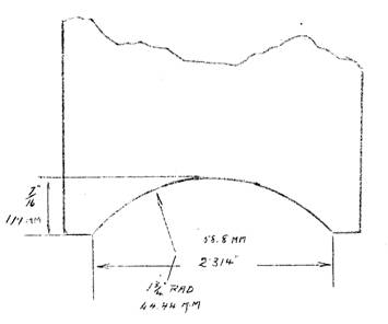
Figure 1. Detail of clearance cut out at cylinder liner.
Bulletin Issue Date: September 1950
Item No. 29. Front Shock Absorbers – PB Models
From Engine Number E0 PB 9877 a new type of front shock absorber has been fitted to Javelin cars. These units incorporate a re-designed lower fixing arrangement which reverses the position of the shock absorber buffer as shown in the sketch on the next page.
It will be noted that the buffer assembly is cut away to provide clearance for the stub axle in the rebound suspension position.
This shock absorber is not fully interchangeable , but may be fitted to previous models by changing the parts as detailed in Spares Note 52.
Item No. 29. Front Shock Absorbers – PB Models (Continued
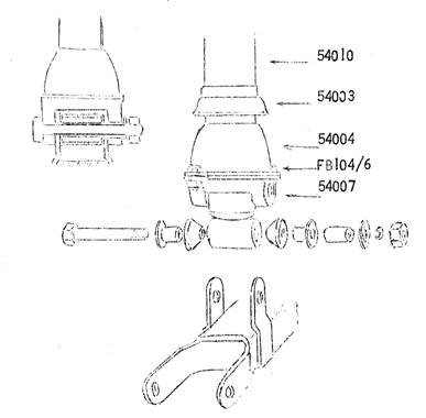
Figure 1. Front shock absorber lower mounting.
Bulletin Issue Date: November 1950
Item No. 30. Steering Ball Joint – PB Models
A re-designed steering ball joint assembly, Part Number 54012, has been fitted to all Javelin cars with effect from Engine Number E0 PB 10789, as shown in the sketch below:
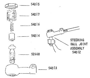
Figure 1. Steering ball joint components.
The new assembly has been designed for ease of dismantling and is fully interchangeable with the previous type of steering ball joint assembly. To adjust the spring tension, release the lock nut, Part Number 54015, and screw the spring retaining nut in a clockwise direction until solid. From this point release the spring retaining nut a quarter of a turn and lock with the lock nut, Part Number 54015.
Item No. 30. Steering Ball Joint – PB Models (Continued)
It is important that there should be a clearance between the neck of the ball and the bore of the socket, Part Number 54013, in all positions throughout the range of suspension movement. When carrying out adjustments to the steering it is necessary to check this point and also the clearance between the socket housing and the steering arm. Refer to illustration in Bulletin Item 16.
The new type ball joint assembly allows an increased range of travel for the ball, and the steering socket is positioned in such a manner as to allow an increased clearance between the housing and the steering arm. Where difficulty is experienced in obtaining the correct clearance on cars fitted with the ball joint assembly, Part Number 52668, the new type steering ball joint assembly, Part Number 54012, should be fitted. The full track and camber check as detailed in Bulletin Item Number 16, should be carried out when fitting the new assembly.
For details of parts changes refer to Spares Note Number 58.
Bulletin Issue Date: November 1950
Item No. 31. Torque Wrench Settings
When assembling the components detailed below it is essential that the securing nuts etc. are tightened with the use of a torque spanner adjusted to the following settings:
lb.ins lb.ft
Cylinder Head Nuts 3/8" BSF* 500 42
Connecting Rod Bolts 3/8" BSF 400 33
Flywheel Set Screws 7/16" BSF 720 60
Cylinder Block Tie Bolts 9/16" BSF 900 75
Swivel Pin Yoke Nut ½" BSF 700 58
Modern Note: Revised to 37 lb.ft with solid copper liner shims.
Bulletin Issue Date: November 1950
Item No. 32. Recommended Lubricants
The following Filtrate Oils have been added to the oil specifications for the Javelin car:
Component Temperature (Climatic) Filtrate Oil Specification
Engine 20 °F to 70 °F Medium Filtrate SAE 30
Over 70 °F Heavy Filtrate SAE 40
Gearbox 20 °F to 70 °F Medium Filtrate SAE 30
Over 70 °F Heavy Filtrate SAE 40
Rear Axle Over 20 °F Hypoid Filtrate Gear Oil 90
Steering Box, Propeller Shaft Centre Bearing High Pressure Solidified Filtrate Oil
and Chassis Lubrication
Suspension Reservoirs Heavy Filtrate SAE 40
Wheel Hubs and Water Pump Filtrate RB Grease
Brake Cables Filtrate Brake Cable Grease
General Lubrication – Fan Spindle, Door Hinges, etc. Medium Filtrate SAE 30
The Lubrication plate, Part Number 51119, will be amended in accordance with the above.
Bulletin Issue Date: November 1950
Item No. 33. Introduction of 1951 Javelin
The new 1951 Javelin has been introduced from Engine Number E0 PC 11326 and from this number all models of the Javelin will bear the prefix letters PC.
Summary of Alterations
Standard and Deluxe Models:
Larger headlights and individual side lights are fitted to both models. The headlights incorporate a dipping arrangement whereby the right hand headlight cuts out in the dip position and the left hand headlight beam is lowered to the left on RHD home models. Dipping of the headlights is non-mechanical and relies on double filament bulbs for operation.
Item No. 33. Introduction of 1951 Javelin (Continued)
The original number plate light and tail light glass has been modified to serve as a number plate light on the Standard model or as a reversing light on the Deluxe model, Part Number 51619. It should be noted that the new light glass is interchangeable on both models as it is possible to alter direction of the beam by turning the bulb holder 180°.
Jack socket plugs, Part Number 54323, have been fitted in order to exclude entry of dirt at the jacking points.
A fuse box, Part Number 51611, has been fitted for separate fusing of electrical components.
Deluxe Models Only:
An improvement to both front and rear bumpers has been made by fitting aprons between the bumper blades and the body. A rear number plate box with an illuminating light has been fitted to the rear bumper blade.
The reversing light as detailed above is operated by means of a switch and switch bracket fitted to the gearbox and adjusted so that the gear lever depresses the switch button when reverse gear is engaged. The starter motor has been turned 180° to increase the clearance between the switch bracket and the starter terminal.
Interior improvements have been brought about by the fitting of a new type steering wheel together with a new horn push. A pair of ash trays have been let into the uppermost face of the fascia panel.
For details of parts changes please refer to Spares Note Number 60.
Bulletin Issue Date: November 1950
Item No. 34. Revised Tappet Assembly – Solid Type
From Engine Number E0 PC 11907 the fitting of the hydraulic tappet has been discontinued and a solid tappet introduced. With the introduction of the new unit the engine components detailed below have been re-designed and are not individually interchangeable with equivalent components on cars prior to Engine Number E0 PC 11907. No alterations have been made however to the crankcases and the re-designed items may be fitted to existing cars in sets.
Description and Special Servicing Points:
Part Number 54151, Camshaft: The camshaft has been modified to obtain satisfactory operation with solid type tappets. The diameter of the base circle is reduced as indicated in the sketch below, the base circle diameter is now 1.0415" (26.454 mm), previously the diameter was 1.070" (27.178 mm). Other dimensions are as previously.
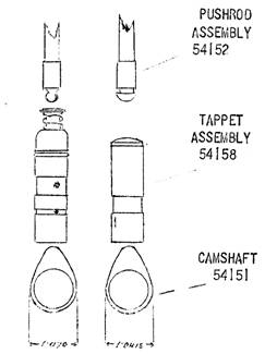
Figure 1. Showing component differences.
Part Number 54161, Tappet: The new unit consists of a cast iron body widely grooved for lubrication, with a bronze insert fitted to the push rod end of the tappet. The insert is shaped to conform with the spherical end of the push rod.
Item No. 34. Revised Tappet Assembly – Solid Type (Continued)
Part Number 54162, Push Rod: The spherical end of the push rod has been increased to minimize wear on the bronze insert of the tappet and the length of the push rod has been increased by 17/32" (13.493 mm).
Please refer to Spares Note Number 61 for parts change information.
Tappet Clearance – With Engine Cold:
Inlet Tappet 0.002" (0.050 mm)
Exhaust Tappet 0.006" (0.152 mm)
Clearance should be checked and re-set at the first 'After Sales Service' (500 miles) and subsequently at every 5,000 miles.
Valve Timing:
For setting the valve timing, arrowheads will continue to be marked on both the crankshaft and camshaft sprockets and are set facing each other as on previous models of the Javelin Engine. The method of checking the valve timing varies only in detail from that outlined in the Manual on Pages 39-40. Reference to this section and the illustration will be helpful. For your further information amended details are outlined below:
1. Rotate the engine until the inlet valve on number 2 cylinder is at the top of its lift.
2. Adjust the valve clearance of number 1 inlet valve to zero.
3. Locate accurately TDC on cylinders 1 and 2, and mark the crankshaft pulley in this position using a pointer attached to a suitable bolt on the timing cover. See Manual, Figure 27.
4. Rotate the engine in the direction of rotation until the crankshaft is some 30 to 40 degrees before TDC on cylinders 1 and 2 and approaching the firing point on cylinder 2.
5. Mount a dial indicator on the rocker assembly operating on the inlet valve of number 1 cylinder as described in the Manual and then rotate the engine until a push rod lift of 0.014" (0.356 mm) to 0.016" (0.406 mm) is indicated.
6. Now measure the distance around the periphery of the pulley from the pointer to the TDC mark on the pulley. If the valve timing is correctly set at 12° before TDC this dimension will be ½" (12.7 mm), but up to 1/8" (30175 mm) tolerance either way, early or late can be allowed. This tolerance represents a maximum variation in valve timing of plus or minus 3°.
Note: The keyway in the crankshaft sprocket is slightly offset in relation to the teeth and some adjustment to the valve timing is possible by reversing it on the crankshaft.
Bulletin Issue Date: November 1950
Item No. 35. Lubrication – Use of Additives
It is again emphasised that only the recommended brands of oil, as detailed in Bulletin Item Number 10 should be used in the Javelin car.
Additives should not, under any circumstances, be used in the hypoid rear axle. We would also point out that we consider the lubrication systems of the engine and gearbox adequate, and therefore the use of additives is unnecessary.
Bulletin Issue Date: February 1951
Item No. 36. Left Hand Crankcase – Connecting Rod Clearance
Further to Bulletin Item Number 28:
With the introduction of the new type of connecting rod, Part Number 54024, which is slightly larger in out-side diameter than the type previously used, Part Number 50650, a flat has been machined on the crankcase boss situated at the rear of number 3 cylinder base inside the LHS crankcase. This is to ensure that there is sufficient clearance between the crankcase boss and number 4 connecting rod bolt.
When fitting the new type connecting rods, Part Number 54024, to vehicles prior to Engine Number E0 PB 10506 it is most important to ensure that there is adequate clearance between the crankcase boss and number 4 connecting rod bolt. Should any doubt exist, a flat may be filed on the crankcase boss as shown in the illustration on the next page. After carrying out this modification great care should be taken to remove all traces of filings etc., from inside the crankcase.
Item No. 36. Left Hand Crankcase – Connecting Rod Clearance (Continued)
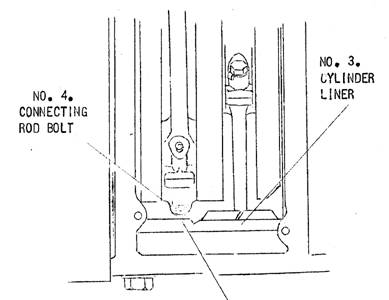
FILE BOSS AT THIS POINT
Bulletin Issue Date: February 1951
Item No. 37. Adjustable Type Selector and Gear Change Links – Right Hand Drive Only
From Engine Number E0 PC 12340 new type adjustable selector, Part Number AS54031, and gear change, Part Number AS54027, link assemblies have been fitted between the gear change column and gearbox on RHD models only. This modification allows a finer and increased range of adjustment on each rod.
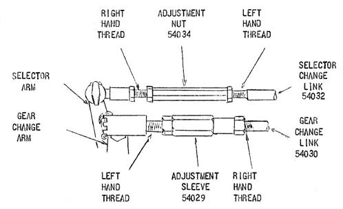
Figure 1. Adjustable gear change links.
Adjustment: The adjustment nut, Part Number 54034, on the selector change link and the adjustment sleeve, Part Number 54029, on the gear change link are provided with left and right hand threads which allow the link to be lengthened or shortened by turning the nut or sleeve after the locknuts have been released. Please refer to the illustration above. The direction of rotation for adjustment works in opposite directions on each link i.e. to lengthen the selector change link the top of the adjustment nut should be turned away from the operator, whereas to lengthen the gear change link the top of the adjustment sleeve should be turned towards the operator.
The new type selector and gear change link assemblies are fully interchangeable with the original assemblies on RHD vehicles. Please refer to Spares Note Number 63 for parts change information.
Bulletin Issue Date: February 1951
Item No. 38. Revised Tappet Assembly – Solid Type
Further to Bulletin Item 34 and Engineering Changes on Page ??
Please note that the solid type of tappet was introduced at Engine Number E0 PC 11907, RHD models, and Engine Number E0 PCL 11940, LHD models, and not at Engine Number E0 PC 11709 as previously stated in Bulletin Item Number 34. The following vehicles built at a later date than E0 PC 11907 but with lower figured engine numbers also have solid tappets fitted:
|
11906 |
11896 |
11878 |
11863 |
11852 |
11842 |
11828 |
11806 |
|
11905 |
11895 |
11877 |
11862 |
11851 |
11841 |
11827 |
11805 |
|
11904 |
11894 |
11876 |
11860 |
11850 |
11836 |
11826 |
11794 |
|
11903 |
11893 |
11870 |
11859 |
11849 |
11835 |
11824 |
11793 |
|
11902 |
11892 |
11869 |
11858 |
11848 |
11834 |
11823 |
11792 |
|
11901 |
11891 |
11868 |
11857 |
11847 |
11833 |
11822 |
11791 |
|
11900 |
11888 |
11867 |
11856 |
11846 |
11832 |
11819 |
11789 |
|
11899 |
11881 |
11866 |
11855 |
11845 |
11831 |
11809 |
11788 |
|
11898 |
11880 |
11865 |
11854 |
11844 |
11830 |
11808 |
11753 |
|
11897 |
11879 |
11864 |
11853 |
11843 |
11829 |
11807 |
– |
The following exceptions have the hydraulic tappet fitted:
|
11912 |
11914 |
11922 |
11938 |
11947 |
11949 |
11952 |
11959 |
11971 |
|
11913 |
11921 |
11937 |
11939 |
11948 |
11951 |
11957 |
11960 |
11972 |
Bulletin Issue Date: February 1951
Item No. 39. Alteration to Specification – Javelin Deluxe Models
In future when 5.50 – 16 tyres are specified for the Javelin Deluxe in place of the standard 5.25 – 16 tyre, the spare wheel carrier, Part Number 51251, from the Standard Model, will be fitted to those vehicles before leaving the factory.
Bulletin Issue Date: February 1951
Item No. 40. Steering Ball Housing Clearance – All Models
SPECIAL ATTENTION!
It is again emphasised that after carrying out Steering track and camber drill as detailed in Bulletin Item 16, it is most important to check the following:
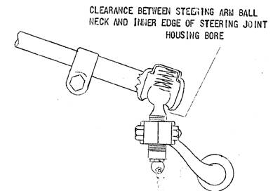
Figure 1. Steering ball nip clearance.
Item No. 40. Steering Ball Housing Clearance – All Models (Continued)
The distance between the steering ball housing and the steering arm must not under any circumstances be less than 1/16" (1.587 mm) with the spring arm in the full rebound position. Please refer to Figure 1 for any clarification of this point.
In addition to the above, it is equally important to check that the bottom inner edge of the bore of the steering ball housing does not foul the neck of the steering arm ball with the suspension in the full rebound position. A satisfactory check may be made with the suspension in the full rebound position and by rotating the steering ball housing which should be free to rotate in a backwards and forwards direction.
If the housing is free to rotate, a clearance is indicated between the inner edge of the steering ball housing and the steering ball neck. Please refer to Figure 1.
If there is little or no free movement, it is apparent that the inner edge of the steering ball housing and the neck of the steering ball are in contact. In this case, immediate action must be taken to fit replacement ball joint assemblies as detailed in Bulletin Item Number 30.
Bulletin Issue Date: February 1951
Item No. 41. Deletion of Steering Rod Cover, Part Number 50570 – All Models
With the introduction of the adjustable type steering ball joint, Part Number 54012, from Engine Number E0 PB 10789, the fitting of the steering rod covers, Part Number 50570, will be discontinued.
Please refer to Spares Note Number 64 for parts change information.
Modern Note: A steering ball joint rubber dust cup is available from Spectrum Rubber, Part Number 285.041 can be ordered from Australian Jowett Car Club stock. Dust should be kept out of this ball joint.
Bulletin Issue Date: May 1951
Item No. 42. Radiator Grille Assembly – PC Model
From Engine Number E0 PC 15631a re-designed radiator grille assembly, Part Number 51587, and bonnet motif have been fitted to all models. The new assembly consists of two separate grilles, upper, Part Number 51520 and lower, Part Number 51521. The louvres are die castings, finished in a satin silver lacquer.
The upper grille is secured at the top in the same manner as with the original Javelin grille and may be hinged upwards to gain quick access to the engine, leaving the lower grille in position.
The lower grille is secured by four quick release spring loaded catches, which locate with four attachment studs on the grille. Provision has been made for adjustment of the lower spring catches.
For parts change information please refer to Page 29 of the PC Model Parts List.
Bulletin Issue Date: May 1951
Item No. 43. Exhaust System – PC Models
From Engine Number E0 PC 15432 rubber bonded mountings have been incorporated in the suspension of the exhaust system. For further details please refer to the illustration and parts information on Page 27 of the Javelin PC Parts List.
Bulletin Issue Date: May 1951
Item No. 44. Fitting of Torsion Bars – All Models
To prevent the octagonal ends of torsion bars corroding and causing difficulty when torsion bar removal is necessary, the ends should be treated prior to fitting with an anti-corrosive solution. A recommended preparation for this purpose is 'Oil Dag', manufactured by:
Messrs. SJ Acheson, 9 Carfere Street, London SW 1.
This product can be obtained from most car accessory stockists.
Bulletin Issue Date: May 1951
Item No. 45. Lubrication of Midship Bearing
Investigations we have recently carried out into the cause of complaints of noisy midship bearings have revealed a state of under-lubrication and/or the use of unsuitable lubricants. Attention is drawn to the advisability of greasing the bearing at 2,500 miles and not at 5,000 miles as previously stated, and to the necessity of using the recommended brands of lubricants.
Bulletin Issue Date: May 1951
Item No. 46. Tow Bar Attachments
Tow bar attachments to fit all Javelin models including the 1951 PC Deluxe models may now be obtained direct from the undermentioned manufacturers:
Messrs. CB Witter, 134 Foxgate Street, Chester,
Messrs. B Dixon Bate Ltd., Chester.
These towing attachments are the same type as those which have been fitted previously, and fitting instructions given on Javelin Technical Circular Number 11 still apply.
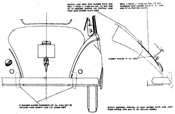
Figure 1. Sketch showing position of rear number plate and light when fitting tow bar.
When fitting the attachment to 1951 Deluxe models, the following modifications will be required:
1. Remove the number plate box from the bumper bar and fit a standard type rear number plate, Part Number 51032, to the rear boot panel in the position shown in Figure 1. Mount the four rubber washers, Part Number 51050.
2. Remove number plate lamp from number plate box and fit to the rear boot panel directly above the centre of the standard type number plate. Wire lamp to existing number plate lamp lead.
3. If over-riders, Part Number 51421, are to be fitted, remove the inner pair of domed securing bolts, Part Number 51575, which hold the bumper main spring to the bumper blade and fit the over-riders to these holes.
4. Fit the two domed securing bolts, Part Number 51575, to the centre pair of holes in the bumper blade where the number plate box was originally fitted.
Figure 1 above shows a PC Deluxe model with above items correctly positioned for the fitting of a tow bar attachment.
Bulletin Issue Date: May 1951
Item No. 47. Air Filter – PA and PB Models
With effect from Engine Number E0 PB 8950 the woodscrews which secure the air filter brackets to the air silencer base, have been replaced by threaded screws and rivet nuts. On cars prior to the above Engine Number where difficulty is experienced with the original filter mounting, modified securing brackets may be fitted. This type of bracket, Part Number 54237, is held firmly in position by four wood screws set at right angles to each other, as shown in Figure 1.
Item No. 47. Air Filter – PA and PB Models (Continued)
Arrangements have been made for the modified brackets to be supplied from our Spares Department.
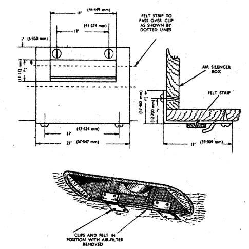
Figure 1. Modified air cleaner bracket arrangement.
Bulletin Issue Date: May 1951
Item No. 48. Steering Wheel – Deluxe PB Models
From Engine Number E0 PC 13111 a new type clear vision steering wheel has been fitted to Deluxe Models. In order to maintain the correct clearance between the steering wheel rim and the gear change lever, when in reverse position, the inner and outer steering column has been lengthened by approximately 3/8" (9.525 mm). If the inner steering column is being replaced on vehicles prior to the above Engine Number by the new type inner column, Part Number 50529, an extension sleeve, Part Number 54362, will have to be fitted to the top of the outer column to take up the space between the outer column and the steering wheel boss. In cases where the outer column is being replaced by the longer type, Part Number AS50533, no modification is required as the inner recess of the steering wheel boss will allow for the outer column's increased length.
The inner and outer columns are fully interchangeable on all models.
Bulletin Issue Date: May 1951
Item No. 49. Hydraulic Tappet Extractor
In cases where difficulty is experienced in removing a hydraulic tappet from the crankcase tappet bore, an extractor may be used as described below:
a) Remove the tappet plunger.
b) Place the extractor in position through the push rod tube bore, with the flared collet end inside the tappet bore.
c) Tighten the extractor barrel nut until the flared collet end of the extractor is expanded and grips firmly in the tappet bore.
Item No. 49. Hydraulic Tappet Extractor (Continued)
d) Hold the extractor central in the push rod tube bore and stroke the extractor head smartly with the ram, until the tappet is drawn clear.
For manufacturing details please refer to illustration below:
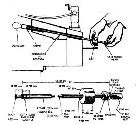
Figure 1. Hydraulic tappet extractor.
In cases where difficulty is experienced in withdrawing the solid type tappet from the tappet bore a firm hold can be obtained on the conical end of the tappet insert. A special puller is therefore not necessary in this case.
Bulletin Issue Date: May 1951
Item No. 50. Oil Pump Release Valve Spring
From Engine Number E1 PC 15098 a modified release valve assembly has been fitted to the oil pump. This will have the effect of increasing the maximum oil pressure from 60 to 70 pounds per square inch. The assembly consists of the following modified parts:
Release valve spring, Part Number 54388
Release valve piston, Part Number 50680
Spring retainer, Part Number 50864
The part numbers for the retainer and the piston remain the same. The release valve piston and spring retainer are interchangeable with the type used prior to the above engine number, but the new release valve spring has been increased in diameter and can not be fitted with the old type release valve piston or spring retainer. It will be necessary therefore, when fitting the new type spring to engines prior to Engine Number E1 PC 15098 to fit the complete modified assembly consisting of spring, piston and retainer. It should also be noted that, due to the diametral increase, the new type spring is not interchangeable with the camshaft thrust spring, Part Number 54388, as was the previous type.
For parts information please refer to Bulletin Spares Note Number 71.
Bulletin Issue Date: May 1951
Item No. 51. Engine Fade Out
Owing to the extreme climatic conditions experienced this winter, we have discovered that certain complaints of misfiring and suspected ignition faults have, in actual fact, been due to the carburettors freezing especially when operating under extreme climatic conditions.
We therefore strongly recommend the fitting of a radiator muff on all cars which operate under these conditions, and would be grateful if you would advise Javelin owners accordingly.
Bulletin Issue Date: July 1951
Item No. 52. Engine Internal Water Leaks
SPECIAL ATTENTION!
It is of extreme importance when carrying out any service operation which necessitates the removal of a cylinder head, that the following points are very carefully checked, to eliminate any chance of internal water leaks after the cylinder head has been refitted.
a) If the engine is turned with the cylinder head removed, there is a possibility of the cylinder liners moving and breaking the cylinder liner seal, Part Number 50643, which results in water seepage into the crankcase after reassembly. To avoid this the cylinder liners should be clamped firmly into position after removing the cylinder head by placing a further tube or number of flat washers over the locating plate tube, Part Number 52143, and tightening down with a cylinder head nut so that the liners are held securely by the liner locating plate, Part Number 52142.
b) To ensure that a satisfactory seal is obtained between the cylinder head gasket, the cylinder head and the top cylinder liner flange and also that the liner is held firmly in position by the cylinder head when assembled, it is essential that the cylinder liner projects from 0.008" to 0.010" (0.203 mm to 0.254 mm) above the crankcase face. This should be checked at all times before replacing a cylinder head and if the projection is not within the above limits, the height should be adjusted by fitting copper shims, Part Number 52381, between the liner sealing flange and the sealing washer, Part Number 50643. Should this action be necessary it is essential that new sealing washers, Part Number 50643, be fitted.
Modern Note: For many years the Jowett Car Club of Australia Inc. has advocated the deletion of the liner sealing washers, Part Number 50643. The recommendation from the club is to substitute the sealing washers with thick solid copper shims, Part Numbers 52381-A, 52381-B and 52381-C, which are 0.020", 0.030" and 0.035" thick respectively. With the successful use of these shim spacers and the introduction of a less-forgiving, modern material cylinder head gasket, the cylinder liner projection figure has been reduced to 0.006" to 0.008". The shim spacers are solid annealed copper and they do compress a small amount during the cylinder head tightening process.
Bulletin Issue Date: July 1951
Item No. 53. Sludge Release Hole – PC Models
From investigations we have recently carried out, we consider it desirable to incorporate a sludge release hole in the connecting rod cap and bearing. This modification has been incorporated from Engine Number E1 PC 17402, and takes the form of a 1/16" (1.5873 mm) hole drilled 30° off centre of the connecting rod cap.
The connecting rod bearing, Part Number 52574, has also been drilled ¼" (9.35 mm) diameter to correspond with the connecting rod drilling.
Arrangements are being made for all service replacement connecting rods, Part Number 54024, and connecting rod bearing shells, Part Number 52574, supplied from our Spares Department to incorporate the sludge release hole.
When vehicles prior to Engine Number E1 PC 17402 are in your service department for engine repairs, the opportunity may be taken to carry out the connecting rod modification as detailed in Figure 1.
It is not advisable to drill the old type connecting rod bearing shells and these should be replaced by the new type which incorporate the sludge release hole.
Item No. 53. Sludge Release Hole – PC Models (Continued)
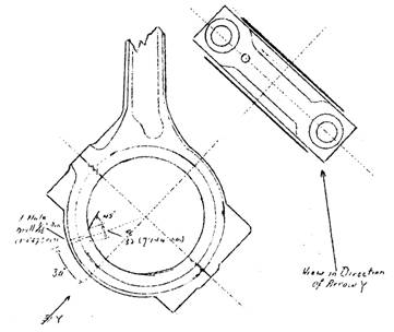
Figure 1. Location of sludge release hole.
Bulletin Issue Date: July 1951
Item No. 54. Shock Absorbers – Front, PC Models
From Engine Number E1 PC 16500 a 25% increased strength shock absorber, Part Number 54385, has been fitted to the front suspension. This will obviate any necessity for the fitting of special type shock absorbers to vehicles using oversize tyres or where operating under extreme road conditions. The existing standard rear shock absorber, Part Number 50467, will still be retained for the rear suspension. A stock of the original type front shock absorbers, Part Number 54010, will be retained for replacement service.
For parts change information please refer to Spares Note 73.
Bulletin Issue Date: July 1951
Item No. 55. Fitting of Spark Plug Shroud – PC Models
To eliminate any risk of water entering between the cylinder head face and the cylinder head top cover, an additional top cover drive screw, Part Number 52140, has been incorporated at the front and rear of the top cover. It is not necessary to carry out this modification on cylinder heads which do not embody the additional rivet holes, but in cases where the cylinder head top cover has been removed a liberal coating of gasket cement should be applied between the shroud and cylinder head face when refitting.
Bulletin Issue Date: July 1951
Item No. 56. Wheel Brace Storage – PC Models
In cases where the shortages of wheel braces occur on Javelin vehicles due to temporary supply difficulties, the owner should be advised that a box spanner is provided in the tool kit suitable for removing or replacing the wheel nuts in case of emergency.
Bulletin Issue Date: July 1951
Item No. 57. Full Flow Oil Filter (Tecalemit) – PC Models
From Javelin Engine Number E1 PC 16603, the Vokes full flow oil filter assembly, Part Number 50872, has been replaced by a Tecalemit full flow oil filter, Part Number 53422. With the introduction of this filter, the rear timing case cover, Part Number 53030, has been re-designed to incorporate a balance valve designed to act as a by-pass in the event of a choked filter
Item No. 57. Full Flow Oil Filter (Tecalemit) – PC Models (Continued)
Servicing Instructions: The periodical servicing of the Tecalemit oil filter remains the same as for the Vokes oil filter i.e. wash out the filter element in clean petrol every 2,500 miles and replace every 10,000 miles.
Special Note: It is extremely important when replacing the oil filter element, that the replacement element is soaked in oil prior to assembly, to avoid any possibility of air locks being formed in the lubricating system.
Stocks of the replacement parts for the Vokes filter will be maintained as the Tecalemit parts are not interchangeable individually with the Vokes filter parts and a full set as detailed below will be required if carrying out a conversion.
1 Timing Case Rear Cover Part Number 53030
1 Blanking Pipe Assembly Part Number 54065
1 Balance Valve Assembly Part Number 53436
1 Oil Filter Assy. Complete Part Number 53422
4 Blanking Pipe Washers (Fibre) Part Number 54157
For Tecalemit item part numbers please refer to Page 11 of your PC List Of Spare Parts.
Bulletin Issue Date: July 1951
Item No. 58. Suppression Condenser – All Models
It has been observed on a number of Javelin cars fitted with a radio, that the suppression condenser has been fitted between the CB terminal on the ignition coil and earth. This is incorrect, as in the event of any slight failure of the suppression condenser it will allow a leak from the ignition circuit giving rise to bad starting and general indifferent performance. In view of this it is essential that the suppression condenser is fitted between the SW terminal of the coil and earth and not the CB terminal as has been the practice in many cases.
Bulletin Issue Date: July 1951
Item No. 59. Oil Pump Filter Level – All Models
A lip has been added to the rear of the oil pump filter housing to ensure that the oil entering the pump filter is not restricted due to the filter face being set too close to the sump base. When initially setting the level of this type filter in relation to the sump a distance of 1/16" (1.5873 mm) should be allowed between the lower edge of the lip and the sump base. When setting the level of oil pump filters which do not embody the above filter housing lip an overall distance of 5/16 (7.94 mm) should be allowed between the filter gauze and the sump base.
A suitable check may be made with the use of a gauge conforming to the sump dimensions, and before the sump is re-fitted the distance between the filter base and the gauge should be checked in accordance with the above.
Bulletin Issue Date: July 1951
Item No. 60. Lubrication Groove, Centre Main Bearing Housing – PC Models
From Engine Number E1 PC 16744 an oil groove has been machined in the centre of the crankcase centre main bearing bore. This allows additional lubrication to the centre main bearing insomuch as in addition to the oil entering the bearing through the bearing shell lubrication hole which is opposite the main crankcase oil feed gallery, the oil can also travel around the groove in the crankcase and enter the bearing at the oil feed hole in the opposite bearing shell.
This modification will be incorporated in all crankcases of factory reconditioned engines.
Bulletin Issue Date: October 1951
Item No. 61. Overheating – PC Models
There is a possibility that a number of Bowman manufactured radiators as fitted to Javelin Cars between approximately Engine Number E1 PC 15910 and E1 PC 17545 have had an excess thickness of paint applied to the radiator tubes. If under normal working conditions (not exceptionally hot and sunny days) a thermometer reading in excess of 81°C is registered, action should be taken to check the following points:
1. Incorrect ignition timing or faulty action on the automatic advance and retard mechanism
2. Loss of water.
3. Temperature gauge registering incorrectly.
Item No. 61. Overheating – PC Models (Continued)
4. Incorrect Carburettor adjustment.
5. Brakes binding.
6. Thermometer sticking.
7. Fan belt slipping.
8. Blockage in cooling system.
9. Incorrect valve timing.
10. Dash side air vent blockage.
11. Is the mileage and engine performance sufficient to indicate that a decarbonising service is required?
12. Fan blade angle incorrect.
In the event of the above points having been checked and found correct and overheating is still experienced, attention should be focussed on the radiator assembly. If the radiator fitted to the car is of Bowman manufacture, which may be identified by a plate fitted to the front of the header tank stamped 'Bowman Birmingham Ltd.', it will be necessary to take the following action:
1. Remove the radiator block and immerse it in thinners until the paint on the honeycombing is loosened and peels away.
2. Remove the block from the thinners and direct a medium force of water through the honeycombing to dislodge any particles of paint which may still adhere to the tubes, and also neutralize the thinners action.
3. Follow this by blowing through the honeycombing with a strong jet of air to remove any paint sediment which may be trapped in the honeycombing.
4. Allow the block to dry and apply a very thin coat of protective paint to the honeycomb and radiator body.
Note: Where vehicles are operating in countries where a high ambient temperature is normally experienced, the thermometer temperature reading will be correspondingly higher than the normal running temperature of approximately 75 °C and in these cases the above action should only be taken when normal running temperatures above 87½ °C are registered.
Bulletin Issue Date: October 1951
Item No. 62. Steering Adjustment – All Models
SPECIAL ATTENTION!
Reports have been received regarding the 'stiffening up' of the steering action, especially in both extreme locks after steering adjustment service has been carried out. Investigations reveal that the stiffness is due to the adjustment of steering internal gear and pinion being carried out with the wheels in a straight ahead position and without allowance being made for the extra wear which takes place on the centre teeth of the internal gear. In view of this, we would again draw your attention to Sections 129, 130 and 131 of the Maintenance Manual which deal fully with steering adjustment and emphasise the necessity for paying special attention to Paragraph 4 of Section 130 which reads as follows:
'To adjust, remove the three set screws securing the column to the box and turn the lock washer until the best possible meshing is obtained, bearing in mind that if wear has taken place this will be mainly in the centre of the gear, and that the adjustment will be limited by meshing on each extreme lock.'
Bulletin Issue Date: October 1951
Item No. 63. Oil Return pipe from Release Valve – Javelin and Jupiter Models
From Javelin Engine Number E1 PC 18985 and Jupiter Engine Number E1 SA 480, an oil outlet tube will be incorporated in the oil pump cover assembly, Part Number 50674. The outlet tube will return the oil passing through the release valve in excess of normal pressure directly back into the oil in the sump, thus eliminating any risk of it becoming aerated. The part number for the new type oil pump cover remains the same and it is fully interchangeable with the previous assembly.
Bulletin Issue Date: October 1951
Item No. 64. Camshaft Knock – Javelin and Jupiter Models
Instances of heavy intermittent engine knock, particularly at slow running speeds, have been traced to camshaft end float. Investigation has indicated that this is due to oil pressure building up between the camshaft boss and the crankcase, thereby causing a 'hydraulicing' action. We have recently introduced a modification in the form of a groove in the crankcase bearing boss to relieve excess pressure at the point as illustrated in Figure 1.
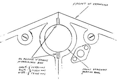
Figure 1. Showing position of oil release grooves.
Camshaft end float is normally controlled by the thrust spring, Part Number 50681, but when any knocking of the nature referred to is experienced, the following action should be taken:
1. Increase the tension of the thrust spring. A simple check may be effected by tapping the camshaft thrust peg, Part Number 54002, into the timing case which will increase the spring loading. If the knock is eliminated the front timing case must be removed and washers of suitable thickness inserted between the thrust pad end and the timing case to re-position the thrust pad.
Special Note: Care must be taken when effecting this repair as the maximum adjustment on the thrust peg is 3/64" (1.191 mm). If this tolerance is exceeded the thrust pad will contact the camshaft chain wheel with subsequent wear.
2. In the event of the check detailed in (1.) proving unsatisfactory:
a) Remove camshaft and complete tappet assemblies.
b) Examine the tappet heads and the camshaft operating cams for damage or excessive wear, and where damage is discovered, the part should be replaced.
3. The opportunity may be taken whilst the camshaft is removed to incorporate the modification in Figure 1, to the crankcase camshaft front bearing boss as described in the first paragraph.
4. Refit the camshaft and tappets and make sure when replacing the tappets, that the units are free to rotate in the crankcase.
5. Re-check the valve timing and complete the reassembly of the engine.
Note: Dimensions for the grooves are as follows:
Length of oil release 'V' groove in crankcase boss 5/8" (15.875 mm)
Depth of 'V' groove in crankcase boss 1/16" (1.59 mm)
Width of 'V' groove in crankcase boss 1/8" (3.17 mm)
Bulletin Issue Date: October 1951
Item No. 65. Water Pump Modification – PC Models
From Engine Number E1 PC 18140, an improved type water pump and fan assembly, which embodies the following modifications has been introduced:
a) Single pressing fan with a taper fitting to the water pump spindle.
b) A slip ring fitted to the water pump impellor to increase circulated volume.
c) The internal diameter of the rear fan spindle bearing, Part Number 50600, has been increased to give additional bearing surface.
d) Threaded studs on the fan spindle bearing housing for the fitting of the fan support struts with the use of 'Oddie' nuts.
Note: To allow a certain amount of flexibility on the water pump supporting stays, the 'Oddie' nuts must not be tightened fully down.
The following parts on the new assembly are not individually interchangeable with corresponding parts on water pumps prior to Engine Number E1 PC 18140, and stocks of these parts will be maintained by our Spares Department for servicing requirements:
1. Water Pump Housing (Part Number J54505)
2. Water Pump Spindle (Part Number 54331)
3. Rear Fan Spindle Bearing (Part Number 50600)
4. Fan Assembly (Part Number 53058)
The new type pump, Part Number J54513, complete with fan assembly is fully interchangeable with the previous type as a complete unit.
For parts change information please refer to Spares Note Number 80.
Bulletin Issue Date: October 1951
Item No. 66. Gear Ratios – PC Models
From Engine Number E0 PC 11270, the number of teeth on the clutch constant drive gear was increased from 18 to 19 teeth and decreased on the layshaft cluster constant drive gear from 34 to 33 teeth. This alteration gives a higher gearbox and final drive ratio in 1st, 2nd, 3rd and reverse gears as detailed below:
Drive Ratios From Engine Number E0 PC 11270.
Gearbox Ratio Final Drive Ratios
Top 1 to 1 Top 4.875 to 1
Third 1.37 to 1 Third 6.700 to 1
Second 2.17 to 1 Second 10.60 to 1
First 3.56 to 1 First 17.40 to 1
Reverse 3.56 to 1 Reverse 17.40 to 1
Drive Ratios Prior to Engine Number E0 PC 11270.
Gearbox Ratio Final Drive Ratios
Top 1 to 1 Top 4.875 to 1
Third 1.50 to 1 Third 7.34 to 1
Second 2.38 to 1 Second 11.60 to 1
First 3.88 to 1 First 19.00 to 1
Reverse 3.88 to 1 Reverse 10.00 to 1
For parts change information details, please refer to Spares Note Number 79.
Bulletin Issue Date: October 1951
Item No. 67. Re-painting of Die Cast Type Radiator Grille – PC Models
In the event of damage to the pyluminize finish on the die cast radiator grille, Part Number 51587, the following procedure should be carried out:
Complete Repaint:
1. Remove all existing paint from the louvres until a perfectly clean surface is obtained.
2. Apply one coat of Pinchin Johnson's light grey cellulose primer.
3. When the primer is thoroughly dry, apply one coat of Postun's Silver Bronze cellulose.
In cases where touching up only is required, taper off the edges of the paintwork around the damaged part before applying the primer and cellulose as detailed above. If difficulty is experienced in obtaining the above grades of primer and cellulose, an alternative propriety brand of primer and cellulose may be used. It may be found, however, when touching in with alternative grades of colour, that the colour shade is not a perfect match with the present finish and in these cases it will be necessary to respray the entire grille.
The addresses of the above paint manufacturers are:
Messrs. Pinchin & Johnson & Co. Ltd., Witley Court, Witley, Surrey.
Messrs. Postuns, Trevor Street, Birmingham 7.
Bulletin Issue Date: October 1951
Item No. 68. Gearbox Extension Bearing Washer – Javelin and Jupiter Models
From Javelin Engine Number E1 PC 18141 and Jupiter Engine Number E1 SA 284, the thickness of the extension bearing locating washers was increased to give additional strength. This necessitated an increase in the depth of the bearing bore in the speedo housing extension tube, Part Number 50044. The complete assembly is interchangeable on all Javelin and Jupiter gearboxes, but it is emphasised that the thicker washer must not be fitted to the previous type extension tube. The new type washers and extension tube will retain their original part numbers with the addition of the prefix letter 'J'.
Stocks of the early type bearing locating washer, Part Number 50121, and speedo housing extension tubes, Part Number 50044, will be maintained by our Spares Department for service requirements.
For parts change information, please refer to Spares Note Number 81.
Bulletin Issue Date: October 1951
Item No. 69. Midship Bearing – All Models
Due to supply difficulties, our Spares Department is not in a position at present to supply the midship bearing assembly, Part Number 50918, complete with bearing as shown in the Javelin PC Parts List. In cases where a replacement bearing is required, the following bearing housing parts should be obtained from our Spares Department:
Qty Description Part Number
1 Midship Bearing Housing 50919
2 Midship Bearing Seals 50923
2 Midship Bearing Seal Retainers 50924
1 Midship Bearing Seal Housing 50925
The bearing (type Skefco RLS 8) should be obtained direct from the manufacturers at the following address:
Skefco Ball Bearing Co. Ltd., Luton, Bedfordshire.
Upon receipt of the above parts, they can be assembled in the following manner:
1. Obtain a suitable metal or hardwood pressing block with a 2 1/8" diameter hole in the centre.
2. Place the midship bearing housing, Part Number 50919, on the block with the lower seal retainer flange inside the 2 1/8" (53.974 mm) diameter hole. This ensures when pressing in the bearing that the pressure is taken by the bearing housing and not by the retainer flange which could easily become distorted under pressure.
3. Fit a felt seal, Part Number 50923, into the lower seal housing followed by a seal retainer, Part Number 50924,. The flat side of the seal retainer should be placed towards the felt seal.
4. Place the assembly on a suitable press and carefully press the bearing into the housing until the lower face of the outer rim of the bearing is in contact with the housing shoulder. The upper rim of the housing should now protrude approximately 3/32" (2.3812 mm) above the top face of the bearing.
Item No. 69. Midship Bearing – All Models (Continued)
5. Place seal retainer on top of the bearing with the face side uppermost. Rest the felt seal on the retainer flat face and fit the seal housing, Part Number 50925, in position over the felt seal and seal retainer, with the rim of the retainer housing below the rim of the bearing housing.
6. The bearing and seal assembly should now be secured in position by turning over the protruding edge of the bearing housing. This can be done with the use of a lathe and a rolling tool, or in the absence of this equipment, the edge can be peened over using hammer and punch method. If the latter course is adopted, care must be taken to ensure that the rim is peened over evenly round the full perimeter of the rim.
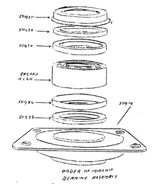
Figure 1. Arrangement of midship bearing components.
Bulletin Issue Date: October 1951
Item No. 70. Torque Wrench Setting – Javelin and Jupiter Models
Front Suspension:
Further to Javelin Bulletin Item Number 31, when carrying out service operations which necessitate the removal of the upper link pin, Part Number 50286, it is most important when re-assembling this unit that the link pin retaining nut be tightened with the use of a torque wrench or spanner adjusted to the following setting:
500 lb.ins. or 42 lb.ft.
Bulletin Issue Date: October 1951
Item No. 71. Connecting Rod Bearings – Javelin and Jupiter Models
Further to Javelin Bulletin Item Number 53:
From Javelin Engine Number E1 PC 18646 and Jupiter Engine Number E1 SA 423, the drilled hole in the rod half of the connecting rod bearing has been deleted. The drilled bearing, Part Number 52574, which fits in the connecting rod cap half will remain the same with the drilling to fit in conjunction with the sludge release hole.
The stocks of un-drilled type bearings as fitted prior to the sludge release hole modification, will now be identified as Part Number J54443 and paired with the drilled bearing, Part Number 52574. the complete bearing assembly consisting of one plain bearing, Part Number J54443, and one drilled bearing, Part Number 52574, will be identified as Part Number J54444.
For parts change details, please refer to Spares Note Number 84.
Bulletin Issue Date: October 1951
Item No. 72. Throttle Rod Assembly – Javelin and Jupiter Models
From Javelin Engine Number E1 PC 18550 and Jupiter Engine Number E1 SA 270, a modified type of throttle rod assembly has been introduced, consisting of throttle rod long, throttle rod short and clamp bolt. The throttle rod long, Part Number 54421 and throttle rod short, Part Number J54422, will fit all Javelin and Jupiter models, but the clamp bolt differs in design for the RHD Jupiter. The clamp bolt part numbers are as follows:
Clamp Bolt – RHD & LHD Javelin and LHD Jupiter, Part Number J54419.
Clamp Bolt – RHD Jupiter only, Part Number 1.53409.
The complete assemblies are fully interchangeable with the previous type throttle linkage on their respective models. For part change details, please refer to Spares Note Number 85.
Bulletin Issue Date: October 1951
Item No. 73. Timing Cover Oil Leak – Javelin and Jupiter Models
To eliminate the possible causes of oil leaks from the rear timing cover, Part Number 53030, and oil filter assembly, Part Number 53422, it is necessary to carry out inspection and fitting instructions as detailed in the following paragraphs:
1. Clean off all oil accumulated on the top area of the crankcase.
2. Run the engine and examine joint faces and attachment points for leaks, the use of a mirror will assist in examination of the underside of the assembly. Instances have been noted where oil leaking from the tappet covers have been mistaken for the rear timing cover fault, note or mark the area where the oil leak is suspected.
3. Remove the rear timing cover assembly, examine and rectify the following points:
a) Damaged face joints which could prevent a satisfactory seal.
b) Examine the drain screw and oil pressure unit tapped holes for cracks.
c) Examine the seat recess where the felt seal, Part Number 52171, is fitted for possible burrs. Place the felt into the recess, the felt should be proud of the main face to ensure the felt is pressed into the recess when the cover is tightened down. If the felt is too thick, reduce to the correct fitting depth, this is important.
d) Chamfer the edges of the bolt holes and the edges of the face joints.
e) Examine the oil filter sealing ring, Part Number 55428, for serviceability.
f) Clean all face joints before fitting.
Refitting the Cover and Oil Filter Assembly:
1. Fit the drain screw and the oil pressure unit or oil pressure pipe union to the cover using a smear of liquid gasket cement to ensure a perfect oil seal. Attention must be directed at the length of the drain screw, the length of this screw should be 1" (25.4 mm), plus the thickness of new fibre washer.
2. Soak the felt seal with an approved liquid gasket cement.
3. Smear the joint faces and the cork packings, Part Number 50692 (rear timing cover gasket), and Part Number 50698 (front timing cover gasket), with liquid gasket cement.
4. Refit the rear timing cover. To ensure a perfect joint, all studs and set screws must be tightened evenly to prevent distortion.
5. Refit the oil filter unit and test the assembly after a road test.
Modern Note: This oil leakage area can be properly repaired by using the technique described on Page 15 of the Jowett Car Club of Australia's booklet 'An Introduction To Overhauling The Jowett Javelin/Jupiter Engine'. This item describes the use of modern sealants and revised assembly procedures.
Bulletin Issue Date: October 1951
Item No. 74. Recommended Lubricants – All Models
Further to Service Bulletin Items Numbered 10 and 32:
When servicing Javelin cars, please advise owners that the following lubrication recommendations supersede those shown in the PA, PB and PC Javelin Instruction books.
Engine and Gearbox – Over 70 °F (UK) Engine and Gearbox – 20 to 70 °F (UK)
Wakefield Castrol XXL Wakefield Castrol XL
Duckhams NOL 40 Duckhams NOL 30
Shell Triple Shell Shell Double Shell
Vacuum Mobiloil BB Vacuum Mobiloil A
Esso Essolube 40 Esso Essolube 30
Prices Energol SAE 40 Prices Energol SAE 30
Filtrate Heavy Filtrate SAE 40 Filtrate Medium Filtrate SAE 30
Engine and Gearbox – Over 70 °F (Overseas) Engine and Gearbox – 20 to 70 °F (Overseas)
Wakefield Castrol XXL Wakefield Castrol XL
Duckhams NOL 40 Duckhams NOL 30
Shell Shell X-100. SAE 40 Shell Shell X-100. SAE 30
Vacuum Mobiloil BB Vacuum Mobiloil A
Esso Essolube 40 Esso Essolube 30
Prices Energol SAE 40 Prices Energol SAE 30
Filtrate Heavy Filtrate SAE 40 Filtrate Medium Filtrate SAE 30
Rear Axle
Wakefield Castrol Hypoy
Duckhams Duckhams Hypoid 90
Shell Shell Spirax 90 EP
Vacuum Mobilube GX 90
Esso Essolube Expee Compound 90
Prices Energol EP SAE 90
Filtrate Hypoid Filtrate Gear Oil 90
Chassis Lubrication – Suspension Nipples, Steering Box, Steering Nipples, Propeller Shaft Centre Bearing, Rear Brake Compensator and Chassis Lubrication:
Wakefield Castrolease Medium or Castrolease CL
Duckhams Duckhams HPG
Shell Shell Retinax A or C
Vacuum Mobilgrease No. 4
Esso Essogrease
Prices UK – Belmoline D, Overseas – Energrease C2
Filtrate HP Solidified Filtrate Oil
Front Suspension Reservoirs:
Wakefield Castrol XXL
Duckhams NOL 40
Shell UK – Triple Shell, Overseas – Shell X-100 SAE 40
Vacuum Mobiloil BB
Esso Essolube 40
Prices Energol SAE 40
Filtrate Heavy Filtrate SAE 40
Front and Rear Hubs, Water Pump:
Wakefield Castrolease Heavy
Duckhams Duckhams HBB
Shell Shell Retinax A or RB
Vacuum Mobilgrease No. 4
Esso Essogrease
Prices UK – Belmoline C, Overseas – Energrease C3
Filtrate Filtrate RB Grease
Brake Fluid:
Girling Crimson Brake Fluid
Item No. 74. Recommended Lubricants – All Models (Continued)
Brake Cables:
Wakefield Castrolease Brake Cable Grease
Duckhams Keenol KG 16
Shell Shell Retinax A or C
Vacuum Mobil Graphited Grease
Esso Essogrease
Prices UK – Belmoline CG, Overseas – Energrease C3G
Filtrate Filtrate Brake Cable Grease
General Lubrication – Fan Spindle, Door Hinges Etc. – As for Engine
Bulletin Issue Date: October 1951
Item No. 75. Support Tube – Javelin and Jupiter Models
From Javelin Engine Number E1 PC 17900 and Jupiter Engine Number E1 SA 270, the cylinder block distance tube, Part Number 52143, has been replaced by a cylinder head gasket support tube, Part Number J54395, and cylinder block distance washer, Part Number J54396. Care must be taken when fitting the new type support tube that its top face is perfectly level with the top face of the cylinder liners, thereby giving additional support to the cylinder head gasket and cylinder head when in position. The height of the support face can be adjusted by fitting brass shim washers below the support tube, or by filing the cylinder block distance washer fitted below the liner locating plate.
For parts change information, please refer to Spares Note Number 86.
Bulletin Issue Date: March 1952
Item No. 76. Camshaft and Chainwheel – Javelin and Jupiter Models
A modified camshaft and chainwheel which gives a finer degree of accuracy when carrying out valve timing adjustment was introduced at Javelin Engine Number E1 PD 19295 and Jupiter Engine Number E1 SA 481.
Six offset dowel holes are incorporated in the chainwheel and in the forward boss of the camshaft which allows the chainwheel to be set in any desired position in relation to the camshaft when carrying out the valve timing operation. To assist further, a 12° mark is also stamped on the flywheel. To carry out valve timing adjustment with the above type camshaft and chainwheel proceed as follows:
1. Rotate the engine until Number 1 piston is at its TDC position.
2. Turn the flywheel anti-clockwise (looking from the front of the engine) until the 12° mark is in the TDC position opposite the centre line of the crankcase.
3. Turn the camshaft until the base of the Number 1 cylinder inlet tappet is resting on the heel of the cam. Adjust the push rod so that it is tight and the valve is slightly open.
4. Fit a dial indicator gauge with the operating rod resting lightly on the top of the tappet and turn the indicator face until a zero reading is registered.
5. Turn the camshaft clockwise until a 0.0130" (0.3302 mm) lift of the tappet is registered on the dial indicator gauge.
6. Fit the chain wheels into the timing chain, and fit them onto the crankshaft camshaft ensuring that the bolt holes in the camshaft chain wheel (slightly elongated) are opposite the bolt holes in the camshaft boss.
7. Locate the chainwheel in this position by examining the relative positions of the dowel holes in the chainwheel and the dowel holes in the camshaft boss and inserting the dowel (reduced end towards the camshaft) into the two camshaft and chainwheel dowel holes which are dead opposite each other.
8. Check the position of the 12° mark on the flywheel and the 0.0130" (0.3302 mm) tappet lift on the dial indicator gauge to ensure that no movement has taken place and, with the setting correct, fit the chainwheel bolt locking plate and securing bolts and lock the securing bolts by folding over the locking plate tabs.
The full assembly which includes camshaft, chainwheel, locking plate and dowel is fully interchangeable with the previous camshaft and chainwheel assembly as a complete assembly, but the parts are not interchangeable as individual items.
For part number change information, please refer to Spares Note Number96.
Bulletin Issue Date: March 1952
Item No. 77. Carburettors, Zenith 30VM – Jupiter
From Engine Number E2 SA 657, the Zenith 30VIG5 carburettors previously fitted to the Jupiter have been replaced by Zenith 30VM type carburettors which incorporate the following settings:
Choke 27 Vent 2.5
Main Jet 120 Needle Seat 1.5
Compensating Jet 65 Slow Running Jet 45
Progression Jet 120 1 mm Washer and Shroud Fitted to Needle and Seat
The carburettors are fully interchangeable with the previous type in pairs and the throttle linkage remains the same. For parts changes please refer to Spares Note Number 87.
Bulletin Issue Date: March 1952
Item No. 78. Air Cleaners – Jupiter
From Engine Number E2 SA 590, the Vokes air cleaner was replaced by two AC type air cleaners. The new type air cleaners consist of two separate units one fitted to each carburettor intake by means of a short extension tube and clips. In cases where the Vokes type air cleaners are being replaced by the later type it will be necessary to remove the electric horns and elongate the horn securing bolt holes in the horn bracket so that the horns may be adjusted to clear the air cleaner body. The AC type air cleaners should be removed and cleaned every 1,000 miles or more frequently if necessary.
To clean the filter, soak thoroughly in petrol and allow to dry off before replacing.
For part change information, please refer to Spares Note Number 88.
Bulletin Issue Date: March 1952
Item No. 79. Lubrication Grooves – Javelin and Jupiter Models
Further to Bulletin Item Number 60, an oil groove is now machined in the centre of the front and rear crankcase main bearing bores in addition to the existing groove in the centre crankcase main bearing bore. The main bearing dowel hole in the crankcase has been counter bored to allow oil to pass around the dowel, but the dowel and dowel locating hole dimensions remain the same, The above modification will be incorporated in the crankcases of all factory reconditioned engines.
Bulletin Issue Date: March 1952
Item No. 80. Oil Filler Tube – Jupiter
From Engine Number E1 SA 504 a shorter type oil filler tube, Part Number 1.53705, has been introduced which gives increased clearance between the tube and the radiator grille. The new type filler tube is fully interchangeable with the previous type.
For part change information, please refer to Spares Note Number 89.
Bulletin Issue Date: March 1952
Item No. 81. Waterproofing Plug Lead Connections – Javelin and Jupiter Models
From Javelin Engine Number E1 PD 19760 and Jupiter Engine Number E1 SA 520 a rubber cover, Part Number J54431, and five plug lead grommets, Part Number J54432, were fitted to the distributor and a rubber sleeve, Part Number J54424, was fitted to each spark plug cover to prevent the ingress of water at the plug lead locations in the distributor cap and spark plug covers. The above items may be fitted to all models prior to the above engine numbers if required.
For part number information please refer to Spares Note Number 90.
Bulletin Issue Date: March 1952
Item No. 82. Petrol System – Jupiter
The Jupiter petrol system has been modified to incorporate a new type petrol pump and petrol filter as follows. From Engine Number E1 SA 439 a new type petrol pump (type SU. PP 36L), Part Number 1.53814, which gives an increased petrol flow was fitted and the position of the petrol pump was changed from the front of the dash panel to the RHS of the chassis.
Item No. 82. Petrol System – Jupiter (Continued)
From Engine Number E1 SA 520, a rubber cover was fitted to the pump to prevent ingress of water and it should be carefully noted when removing and replacing the cover that the 1/16" (1.5873 mm)breather hole should be positioned to the underside of the pump. From Engine Number E1 SA 504 the three-way petrol tap and reserve supply system was dispensed with and replaced by a single pipe from the petrol tank direct to the petrol pump. At the same engine number a new type petrol filter, Part Number J54436, was introduced and the position of the petrol filter was changed from the front dash panel to the RHS of the chassis.
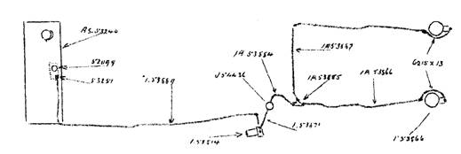
Figure 1. Fuel system showing component part numbers.
The petrol pipe layout was modified to suit the new position of the petrol pump and filter as shown in the sketch above. For part changes please refer to Spares Note Number 91.
Bulletin Issue Date: March 1952
Item No. 83. Gearbox Selector Fork, 3rd and Top – Javelin and Jupiter
To prevent gear lever vibration the width of the third and top selector fork has been increased for a distance of approximately 5/8" (15.875 mm) from the ends of the fork by 0.020" (0.508 mm) as shown below. With this modification the 5/8" (15.875 mm) increased width portion of the fork only contacts the sliding groove when the sliding sleeve is being moved axially on the driving dog, thereby eliminating any tendency for the sliding sleeve to be incorrectly aligned when in full engagement with the gear dog teeth.
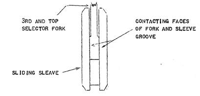
Figure 1. Third and top sliding sleeve and selector fork.
The increased width of the selector fork necessitates an increase in the width of the sliding sleeve groove, and the fork and sleeve are only interchangeable with the previous type in pairs.
For part change information please refer to Spares Note Number 92.
Bulletin Issue Date: March 1952
Item No. 84. Gear Change Stay – Javelin
From Engine Number E1 PD 20135 an adjustable gear change stay assembly, Part Numbers J54497 RHD and J54506 LHD, was introduced. This adjustment makes it unnecessary to use force when fitting the stay to its location on the clutch housing.
The new stay is fully interchangeable with the previous type as a complete assembly.
For part change information please refer to Spares Note Number 94.
Bulletin Issue Date: March 1952
Item No. 85. Water Pump and Fan – Javelin and Jupiter
Further to Bulletin Item Number 65, from Javelin Engine Number E2 PD 20379 and Jupiter Engine Number E2 SA 575, a non stick taper has been introduced to the water pump spindle to facilitate the removal of the fan. This modification incorporates a sharper taper at the fan location end of the spindle. The new type fan and spindle are fully interchangeable as a pair with the types previously fitted, but not as individual items.
For parts information please refer to Spares Note Number 100.
Bulletin Issue Date: March 1952
Item No. 86. Flywheel Ring Gear – Javelin and Jupiter
An increased tooth chamfer which runs parallel with the pressure side of the ring gear tooth is now incorporated on all flywheel ring gears fitted to Javelin and Jupiter cars. This modification gives improved 'lead-in' for the starter Bendix drive gear thereby cutting down to a minimum any tendency for the flywheel ring gear teeth to become burred or damaged due to initial contact between the two gears.
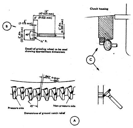
Figure 1. Starter ring gear modification.
If starter jamming is experienced on vehicles with the previous type ring gear fitted, due to burrs or damage at the edges of the ring gear teeth the chamfer should be increased to the dimensions shown at (A) above, by grinding the flywheel ring gear as shown at (C). This operation may be carried out on Javelin and Jupiter models with the engine in position using a grinding wheel of the dimensions shown at (B). The new type ring gear is fully interchangeable with the previous type and the fitting instructions remain the same.
For part number changes, please refer to Spares Note Number 101.
Bulletin Issue Date: March 1952
Item No. 87. Gearbox, Oil Capacity – Javelin and Jupiter
Please note that 1 pint (0.56 litre) of oil is sufficient to fill the gearbox to its correct level and not 1½ pints (0.85 litre) as specified in the instruction book .
Bulletin Issue Date: March 1952
Item No. 88. Fitting of Oil Cooler – Javelin all Models
On all Javelins delivered into the Home Market as and from January 7th, 1952, and into the Overseas Markets from January 14th, 1952, the oil cooler (radiator mounted type) became a standard fitment, but, owing to material shortages, the coolers were not fitted to all cars leaving the factory after the above dates, and arrangements have been made to make up the shortages with the minimum of delay, and agents advised accordingly by Technical Circular.
For all Javelin models from 1948 and prior to those delivered before the above dates, the competition oil cooler is available and supplies can be obtained from the Spares Department. Installation instructions for this type of cooler are detailed below.
Fitting a Competition Type Cooler to Cars Fitted With Tecalemit Filter:
1. Remove the oil filler tube and modify to the dimensions given at (A), so that it will clear the cooler. See Figure 1 below.
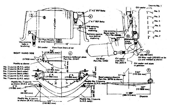
Figure 1. Mounting of competition type oil cooler (with Tecalemit oil filter).
2. Shape the dipstick to the dimensions at (B), so that it clears the oil cooler when being withdrawn or being replaced. See Figure 1.
3. Remove the radiator grille and remove the deflector plate as shown at (C) Figure 1. Cut away the portions of the grille portions as shown, so that there is clearance between the oil cooler and the Grille. If the grille is of the early type with the chromium-plated louvres, no modification to the louvres is required, but it will be necessary to remove the brace frame, and to fabricate and fit a modified brace frame, as shown in Figure 2, on Page 42.
4. To fit the cooler, remove the captive nuts at the rear of the mudwing and drill the lower cooler brackets to coincide with the existing holes in the mudwing and secure with two 1/4 " x 1" BSF bolts and nuts with the distance pieces positioned between the lower cooler brackets and the mudwing as shown at (D) in Figure 1. Drill the grille frame corner pieces and top cooler bracket holes and secure with the use of two ¼" x 5/8" BSF bolts as shown at (E) in Figure 1.
5. Fit the cooler pipes in position as shown in Figure 1, using the existing banjo bolts and fibre washers at the rear timing cover connections.
The parts required for fitting the oil cooler to engines incorporating the Tecalemit oil filter are as follows:
Item No. 88. Fitting of Oil Cooler – Javelin all Models (Continued)
Part Number Qty. Description
JSK506 1 Oil Cooler (Competition Type)
J54519 2 Oil Cooler Feed Pipe
1.53053 2 Oil Cooler Pipe Inner Sleeve
1.53054 2 Oil Cooler Pipe Nipple
J54579 2 Distance Piece
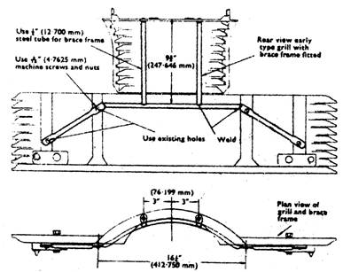
Figure 2. Fitting of brace frame to early type grille.
Fitting of Cooler to Cars Fitted With the Vokes Type Oil Filter:
When fitting the competition type oil cooler, Part Number JSK506, to cars having the Vokes type of oil filter it will be necessary to modify the filter in addition to carrying out operations 1, 2, 3 and 4 as described for the fitting of an oil cooler to engines incorporating a Tecalemit oil filter, as the design of the rear timing case cover is different and does not embody any adaptors to which the oil cooler pipes can be connected. It is necessary therefore to modify the internal construction of the oil filter so that the oil is directed through the oil cooler after passing through the filter and also to fit two adaptors to the filter case to which the cooler pipes can be connected. To carry out this modification proceed as follows:
1. Fit the blanking ring, Part Number 53046, to the oil filter case as shown at (F) Figure 3a and secure in position by riveting or sweating, do not weld or braze as this method would tend to cause distortion.
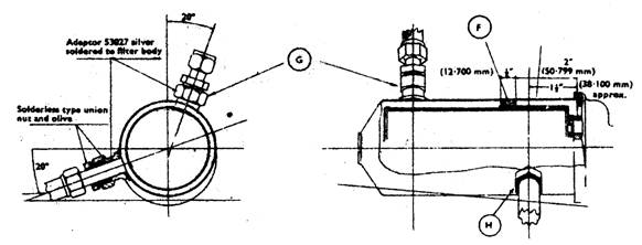
Figure 3a. Vokes oil filter modification.
2. Drill two ½" (12.700 mm) holes in the filter case in the positions shown at (G) and (H) in Figure 3a, and fit the oil cooler pipe adaptors, Part Number 53027. Secure the adaptors to the case with silver solder.
Item No. 88. Fitting of Oil Cooler – Javelin all Models (Continued)
3. Butt solder the shroud, Part Number 53045, as shown at (J) Figure 3b, and after removing the three lugs from filter element front plate, sweat the shroud to the front plate in the position shown at (K) Figure 3b.
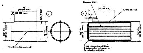
Figure 3b. Vokes oil filter element modification.
4. After fitting the shroud to the element test it for fit in the filter case blanking ring. The shroud form a good seal inside the blanking ring but at the same time it must be a good sliding fit so that it allows the element assembly to move backwards and forwards for filter blow-off purposes. To check the fit place the filter element spring and element in the filter case in their normal positioned and press the element down until the spring is compressed, When released the element should move back to its former position without any signs of undue tightness.
5. The parts required when fitting the competition type oil cooler to an engine incorporating the Vokes type oil filter are as follows:
Part Number Qty. Description
JSK506 1 Oil Cooler (Competition Type)
52985 1 Oil Cooler Pipe 15" (381.00 mm) Long
53026 1 Oil Cooler Pipe 12" (304.796 mm) Long
54579 2 Distance Piece
53027 2 Adaptors
1.53054 4 Oil Pipe Nipple
53053 4 Oil Pipe Inner Sleeve
53046 1 Blanking Ring
53045 1 Filter Element Shroud
Bulletin Issue Date: March 1952
Item No. 89. Distributor, Type DM2 – Javelin and Jupiter
From approximately Javelin Engine Number E2 PD 21016 and Jupiter Engine Number E2 SA 717 the distributor type DKY H4A, Part Number 50773, is replaced by the DM2 type, Part Number J54516, which embodies a micrometer adjustment unit. The mounting flange on the timing cover is modified to suit the new type distributor securing plate and the new type timing cover, Part Number 54662, has also been changed. The DM2 distributor may be fitted to the old type timing cover by increasing the width of the elongated hole in the securing plate as shown in Figure 1.
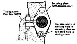
Figure 1. Installation of securing plate on early type timing cover.
Item No. 89. Distributor, Type DM2 – Javelin and Jupiter (Continued)
The old type distributor (DKY H4A) can be fitted to the new type timing cover by removing the forward lug of the timing cover mounting flange and fitting a distributor locating bracket, Part Number 54661, to the rear lug of the timing cover mounting flange as shown in Figure 2.
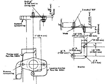
Figure 2. Installing Lucas DKY H4A distributor on later type timing cover.
Note: The point gap setting for the DM2 is 0.014" to 0.016" (0.3556 to 0.4064 mm) and not 0.010" to 0.012" (0.254 to 0.3048 mm) as for the DKY H4A. When timing the ignition it should be set at TDC with the micrometer adjustment setting in a central position so that final adjustment may be carried out on road test. The distributor body is stamped to indicate the direction in which the micrometer adjustment should be turned when advancing or retarding.
All part number changes for the above will be fully detailed in the new PD Javelin Parts List.
Bulletin Issue Date: May 1952
Item No. 90. Engine Internal Water Leaks and Gasket Failures – Javelin and Jupiter All Models
Special Attention
From reports we have received it would appear that the information, as detailed in Bulletin Item Number 52, is not receiving sufficient attention. We therefore cannot over emphasise that when a vehicle is in your Service Department for repair which necessitates cylinder head removal, the following action is taken:
1. Clamp the cylinder liners firmly in position with the use of a tube or a number of flat washers over the locating plate tube, Part Number 52143, and tightening down with a cylinder head nut to avoid liner movement when the engine is turned.
2. The cylinder liner top flange must at all times project from the crankcase between 0.008" and 0.010" (0.2032 and 0.254 mm) to ensure that a satisfactory seal is obtained between the cylinder head gasket, the cylinder head and the cylinder liner. This distance must at all times be checked and where necessary the liner height adjusted with the use of copper shims inserted between the cylinder liner and the cylinder liner sealing washer, Part Number 50643. New sealing washers should at all times be fitted when the seal has been disturbed.
3. The cylinder head gasket centre support should be fitted as detailed in Bulletin Item Number 75.
Item No. 90. Engine Internal Water Leaks and Gasket Failures – Javelin and Jupiter (Continued)
4. We would also draw to your attention to the fact that Javelin and Jupiter cylinder head gaskets are not interchangeable, and emphasize the importance of using the correct type of replacement, detailed below:
Jupiter
Cylinder Head Gasket Part Number 1.53691
Cylinder Head Stud, Long Part Number 50637 (EN 16 Steel)
Cylinder Head Stud, Centre Part Number 52110 (EN 16 Steel)
Cylinder Head Stud, Short Part Number 50636 (EN 16 Steel)
Javelin
Cylinder Head Gasket Part Number 50738
Cylinder Head Stud, Long Part Number 50637 (EN 16 Steel)
Cylinder Head Stud, Centre Part Number 52110 (EN 16 Steel)
Cylinder Head Stud, Short Part Number 50636 (EN 16 Steel)
The torque wrench setting on both cars is 500 lb.ins (42 lb.ft)
Modern Note: For many years the Jowett Car Club of Australia Inc. has advocated the deletion of the liner sealing washers, Part Number 50643. The recommendation from the club is to substitute the sealing washers with thick solid copper shims, Part Numbers 52381-A, 52381-B and 52381-C, which are 0.020", 0.030" and 0.035" thick respectively. With the successful use of these shim spacers and the introduction of a less-forgiving, modern material cylinder head gasket, the cylinder liner projection figure has been reduced to 0.006" to 0.008". The shim spacers are solid annealed copper and they do compress a small amount during the cylinder head tightening process.
Bulletin Issue Date: May 1952
Item No. 91. Petrol Pipe Assembly – Javelin
From Javelin Engine Number E2 PD 21147, the petrol feed pipe from the petrol pump to the carburettors was modified to accommodate an AC Sphinx petrol filter, Part Number J54436, for improved filtering of the petrol. The petrol filter is connected to the 'T' piece connection on the petrol feed pipe between the carburettors and the intermediate petrol feed pipe from the petrol pump. With this modification, the fuel strainer in the petrol tank was deleted. The new type petrol pipe assembly is fully interchangeable with the previous type. For parts information please refer to Spares Note Number 106.
Bulletin Issue Date: May 1952
Item No. 92. Sludge Release Hole – Javelin and Jupiter
Further to Bulletin Item Number 53.
From further investigations recently carried out, it has been decided to delete the 1/16" (1.5873 mm) hole from the connecting rod cap to prevent pressure 'hammer' in the oil system. The drilling in the connecting rod shells, Part Number 52574, are retained as previously stated and the corresponding countersunk recess in the inner side of the connecting rod cap is incorporated to receive any foreign matter which may have reached the connecting rod bearing.
Part numbers for the connecting rod bearings remain as detailed in Spares Note Number 84.
This modification was introduced from Javelin Engine Number E2 PD 20977, and from Jupiter Engine Number E2 SA 692.
Bulletin Issue Date: May 1952
Item No. 93. Lubrication of Fan Spindle Bearing – Javelin
With the introduction of the radiator mounted oil cooler the fan support tube oil cup, Part Number J54011, was inaccessible and therefore removed. A 3/16" (4.7625 mm) hole is now incorporated in the fan support tube for lubrication purposes together with a 1/8" (3.175 mm) spill hole to prevent over lubrication.
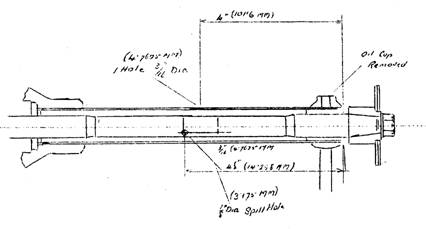
Figure 1. Dimensions for drilling fan support tube.
Bulletin Issue Date: May 1952
Item No. 94. Gear Change Stay – Javelin All Models
Further to Bulletin Item Number 84:
From Engine Number E2 PD 20144 a modified gear change stay was introduced to all Javelin cars. This modification gives added strength to the gear change stay and takes the form of a pressed steel stay, Part Number J54584 (RHD), and Part Number 54596 (LHD), which replace the rods incorporated with the previous type gear change stays, Part Number J54498 (RHD), and Part Number J54507 (LHD). The revised type gear change stay is interchangeable with the previous type on RHD Models and the modified gear change stay and stay rod eye, Part Number J54630, together are interchangeable with those on LHD Models.
For parts information, please refer to Spares Note Number 105.
Bulletin Issue Date: May 1952
Item No. 95. Crankshaft and Rear Main Bearing Identification – Javelin and Jupiter
Further to Bulletin Item Number 2. Undersize crankshaft sizes and increase in the width of the rear main bearing journal and rear main bearing shells can be identified as follows:
The amount of undersize of the front and centre main bearing journals, and the amount of undersize and increase in width on the crankpin journals will be stamped on the outside of the crank web at the rear of Number 1 connecting rod journal as follows:
The part number of the reconditioned crankshaft, which is R50647, is followed by the crank pin undersize, followed by the front and centre main bearing journal undersize. In cases where the crank pins have been increased by 0.025" (0.635 mm), the above numbers will be followed by the letter 'O'. For Example, a crankshaft stamped with 0.010" (0.254 mm) undersize connecting rod journals and 0.005" (0.127 mm) undersize front and centre main bearing journals and with an increase of 0.025 (0.635 mm) in crankpin journal width would be stamped as follows:
R50647/10/5/O
In the case of the rear main bearing journal, where the width may be increased, the identification numbers will be stamped on the outside of the crankshaft web at the rear of Number 4 connecting rod bearing journal. In this case the reconditioned crank shaft part number will be followed by the rear main bearing undersize number and the increase in width number i.e. if the rear main bearing journal had been reground to 0.010" (0.254 mm) undersize with a 0.005" (0.127 mm) increase in width the stamping would read as follows:
R50647/10/5
Item No. 95. Crankshaft and Rear Main Bearing Identification – Javelin and Jupiter (Continued)
The rear main bearing journal will be increased in width in comparison with the undersize as follows:
Standard and 0.005" (0.127 mm) Undersize – no increase in journal width.
0.010" (0.254 mm) Undersize – 0.005" (0.127 mm) increase in width.
0.020" (0.508 mm) Undersize – 0.010" (0.254 mm) increase in width.
The rear main bearing shell width will be increased in comparison to the undersizes as follows:
Standard and 0.005" (0.127 mm) Undersize – no increase in journal width.
0.010" (0.254 mm) Undersize – 0.005" (0.127 mm) increase in width.
0.020" (0.508 mm) Undersize – 0.010" (0.254 mm) increase in width.
For identification purposes, the part number followed by the undersize number, followed by the width increase number will be stamped on the outside face of the bearing as follows:
50646/5 50646/10/5 50646/20/10
Bulletin Issue Date: July 1952
Item No. 96. Front Suspension – Javelin and Jupiter
From Javelin Engine Number E2 PD 21868 and Jupiter Engine Number E2 SA 865, the front suspension has been re-designed in accordance with the 1952 specification. The suspension is mounted on conical rubber bushes, and does not require lubrication. The upper link bracket is replaced by a cast aluminium type bracket and the upper link is manufactured in two sections to facilitate the assembly of the rubber bushes.
The new type swivel pin yoke is a screw fit to the swivel pin and thrust between the yoke and stub axle is taken by a steel thrust washer.
New type shock absorbers of Armstrong manufacture are fitted which incorporate an internal bump stop, the lower spring arm has been modified to accommodate the new rubber mounting for the swivel pin. The new type suspension and shock absorber assembly together with the stub axle and front hub assembly is fully interchangeable with the previous type suspension.
Bulletin Issue Date: July 1952
Item No. 97. Shock Absorbers, Armstrong Type – Javelin and Jupiter
With the introduction of the new type front suspension at Javelin Engine Number E2 PD 21868 and Jupiter Engine Number E2 SA 865, Armstrong type shock absorbers were fitted to the front and rear suspension. The front shock absorbers, Part Number J54470, incorporate an internal rubber bump stop and are only interchangeable on Javelin and Jupiter Models incorporating the new type front suspension. The rear shock absorbers, Part Number J54529, are interchangeable on all models, but it is strongly recommended that the Armstrong type is always fitted to models incorporating the new type front suspension and not to previous models.
Bulletin Issue Date: July 1952
Item No. 98. Radiator Improved Cooling – Jupiter
From Jupiter Engine Numbers E1 SAL 458 (LHD) and E2 SA 695 (RHD) a new type radiator, Part Number 1.53728, with an increased cooling area has been introduced. The increased area necessitates an increase in height to the radiator, and the top engine shield, Part Number 56104, is discontinued. The new type radiator is interchangeable with the previous type of RHD and LHD models.
Bulletin Issue Date: July 1952
Item No. 99. Locking of First Gear – Javelin and Jupiter
At Javelin Engine Number E2 PD 20641 and Jupiter Engine Number E2 SA 657, a modification was introduced to improve the locking of the first gear when in an engaged position. This modification takes the form of a further groove ground on the internal splines of the 1st sliding gear, Part Number J54577, to mate with the synchro balls when engaged in first gear position. The 1st and 2nd sliding dog, Part Number J54670, outside diameter is fully splined and the lock plunger drilling has been counter bored to accommodate an improved type gear lock plunger, Part Number J54649.
The countersunk recess on the main shaft (third motion shaft), Part Number J54671, which locates the gear lock plunger, has been modified to accommodate the shank of the improved type plunger. It is essential to ensure that any rough edges, which may be found on the lock plunger, are cleaned off and that the plunger is an easy sliding fit to the sliding dog and the recess in the main shaft.
Item No. 99. Locking of First Gear – Javelin and Jupiter (Continued)
To assemble the gear and plunger the following drill should be carried out:
1. Fit the plunger spring over the reduced shank of the gear lock plunger, and together insert them into the counter bored drilling in the sliding dog.
2. Fit the synchro springs and balls into their respective drillings and fit the sliding gear to the sliding dog with the reduced internal spline in line with the gear lock plunger.
3. When fitting the gear assembly on to the main shaft ensure that it is an easy sliding fit.
The above items are interchangeable in sets only to vehicles prior to the above engine numbers.
Bulletin Issue Date: September 1952
Item No. 103. Crankcase Oil Galleries, Increased Flow – Javelin and Jupiter
At Javelin Engine Number E2 PD 21937, the dimensions of the oil feed holes from the oil pump body, oil delivery pipe and timing case rear cover, were increased in diameter to increase the flow of lubricating oil to the crankshaft and connecting rod bearings.
At Javelin Engine Number E2 PD 22160, with the exception of the following numbers:
E2 PD 22175, E2 PD 22178, E2 PD 22182 and E2 PD 22186
The oil feed hole through the crankcase from the oil delivery pipe to the timing case rear cover was increased in diameter for further improvement to the oil flow.
The tappet oil feed gallery has been repositioned and lubrication of the tappets is by a 3/32" (2.381 mm) diameter hole drilled through the wall of the tappet housings into the oil gallery, thereby allowing sufficient lubrication to the tappets thus eliminating the possibility of excessive oil leakage.
The drilling in the crankcase locating the overhead valve rocker gear oil feed pipe has been increased in diameter to bring into line with the repositioned oil gallery and incorporates an adaptor. The existing valve rocker oil pipes and olives are connected to the adaptors by union nuts.
At Jupiter Engine Number E2 SA 882, all of the above modifications were incorporated.
The following modified parts are not individually interchangeable with the previous parts and it is now strongly recommended that they should only be fitted to the modified crankcase, which retains its original part numbers.
Part Number Qty. Description
J54555 1 Oil Pump Body
J54554 1 Oil Delivery Pipe
J54552 1 Oil Pipe Elbow Washer (Gasket)
J54548 3 Oil Delivery Pipe Union Bolt
J54549 6 Oil Pipe Union Fibre Washer
J54547 1 Timing Case Rear Cover
J54573 2 Oil Pipe Adaptors (Rocker Feed)
J54474 2 Union Nuts (Should the Part Number be J54574?)
J54688 1 Timing Case Rear Cover Gasket
Bulletin Issue Date: September 1952
Item No. 104. Crankshaft, Improved Design – Javelin and Jupiter
At Javelin Engine Number E2 PD 22190 and Jupiter Engine Number E2 SA 882, with the addition of the following Javelins:– E2 PD 2216, E2 PD 22162, E2 PD 22163, E2 PD 22170, E2 PD 22173, E2 PD 22175. E2 PD 22176, E2 PD 22178, E2 PD 22179, E2 PD 22180, E2 PD 22181, E2 PD 22183, E2 PD 22184, E2 PD 22185, E2 PD 22186, E2 PD 22187 and E2 PD 22188, a modified crankshaft assembly, Part Number J54593, was introduced. The radii of the crankshaft journals and crankpins have been increased to 0.100" (2.54 mm). The crankshaft has been lightened by a 15/16" (23.812 mm) hole drilled horizontally through the crank pins and the oil feed holes have been drilled offset to avoid the lightening holes.
The lock notch in the big end bore of the modified connecting rod and cap assembly, which now bears the Part Number J54591, has been machined 0.040" (1.016 mm) nearer the centre of the bore face to accommodate the modified connecting rod bearing (plain), Part Number J54589, and connecting rod bearings (drilled), Part Number J54588, which have been decreased in width.
The front and centre main bearings, Part Number 52573, have been decreased in width to allow for the larger radii of the crankshaft. The rear main bearing, Part Number 50646, has not been altered in width, but the corner profiles have been modified to allow for the larger radii on the crankshaft although the part numbers for the main bearings have not altered, only bearings of Vandervell manufacture stamped 'LTD'
Item No. 104. Crankshaft, Improved Design – Javelin and Jupiter (Continued)
should be fitted to the modified type crankshaft. The early type main bearings and connecting rod bearings cannot be fitted to the modified crankshaft. Late type main and connecting rod bearings and connecting rods, can be fitted to the early type crankshaft. Reconditioned crankshafts, connecting rod assemblies and undersized bearings of the new type, will be stamped with the new part numbers, followed by the undersizes as detailed in the Bulletin Item Numbers 2 and 95.
NOTE: From the introduction of this modification a number of crankshafts have been fitted which do not incorporate the lightening holes. The modified crankshaft can be identified by the offset position of the oil feed holes and the increased radii on the crankpins and journals.
Bulletin Issue Date: September 1952
Item No. 105. Connecting Rods and Bearings – Javelin and Jupiter
At Javelin Engine Number E2 PE 22451, and Jupiter Engine number E2 SA 938 with the following additions:
Javelin: E2 PE 22444, E2 PE 22447 and E2 PE 22449
Jupiter: E2 SA 820, E2 SA 821, E2 SA 822, E2 SA 824, E2 SA 825, E2 SA 826, E2 SA 829,
E2 SA 830, E2 SA 832, E2 SA 834, E2 SA 835, E2 SA 836 and E2 SA 837
The connecting rod bearings, Part Number J54588 (drilled) and Part Number J54589 (plain), have been replaced by two plain Vandervell bearing shells, Part Number J54710, which incorporate a 1/8" (3.175 mm) lock notch. The lock notches in the connecting rod have been reduced in width accordingly and the drilled recess in the connecting rod cap has been discontinued. This modification obviates any tendency of the lock notch to run in line with the oil feed holes in the crankshaft, which may result in a 'flutter' in the oil system. The late type connecting rod, Part Number J54727, and bearings together, are fully interchangeable with the previous type connecting rod, Part Number J54591, and bearings.
Bulletin Issue Date: July 1952
Item No. 107. Steering Wheel, Splined Fitting Type – Javelin PD Models
From Javelin Deluxe Engine Number E2 PD 20881 and Javelin Standard Engine Number E2 PD 21838, a splined fitting type steering wheel was introduced to facilitate the removal, replacement and positioning of the steering wheel so that a clear view of the instrument panel may be obtained between the steering wheel spokes when the road wheels are in a straight ahead position. The fitting of the improved type of steering wheel necessitates the tapered end of the steering internal column being replaced by a splined insert. The steering column felt bearing locating collar is integral with the insert and does not allow the removal and replacement of the horn slip ring, which together with the steering internal column are supplied only as an assembly. A distance piece is fitted between the steering wheel and the shoulder at the upper end of the internal column to facilitate the fitting of the felt bearing. The late type steering wheel, Part Number J54539 (Deluxe) and 53338 (Standard), and steering internal column, Part Number J54528, together with the distance piece, Part Number 54511, are fully interchangeable with the previous type steering wheel and internal column.
Bulletin Issue Date: September 1952
Item No. 108. Shock Absorbers, Woodhead Monroe Type – Javelin and Jupiter
Further to Service Bulletin Item Number 97. At Javelin Engine Number E2 PE 22346 and Jupiter Engine Number E2 SA 921, the Armstrong shock absorbers were discontinued and replaced by the Woodhead Monroe type. The front shock absorbers incorporate an internal rubber bump stop and are only interchange-able on Javelin and Jupiter models incorporating the new type front suspension. When fitting replacements both shock absorbers should be of the same type.
The rear shock absorbers are interchangeable on all models and when fitting replacements both shock absorbers should be of the same type.
Bulletin Issue Date: September 1952
Item No. 109. Chassis Height – Javelin all Models
From investigations recently carried out it has been decided to decrease the setting of the chassis height from 10¼" (260.350 mm) to 9¾" – 10" (247.050 mm – 254 mm).
The above alteration decreases the load to the torsion bars resulting in a smoother action of the front suspension.
Bulletin Issue Date: September 1952
Item No. 110. Improved Body Mounting – Jupiter
An improved body mounting has now been introduced to eliminate the possibility of movement between the body frame and the chassis, In cases where complaints are received of steering kick, coupled with front end vibrations, it will be necessary to incorporate the following modifications and fit the parts described below:
1. Remove the bonnet and front wing assembly, windscreen wiper motor, starter solenoid and horn relay on RHD models, the wiper motor on LHD models, and the four Silentbloc bushes of the front and centre body mountings. Where the Vokes type air cleaner is fitted on the dash panel, it will be necessary to remove and fit the two independent air cleaners.
2. Place a ½" (12.7 mm) flat washer, outside diameter 1½" (38.099 mm) by 3/32" (2.381 mm) thick into the existing holes in the body support bracket assemblies on the chassis to centralise the mounting bolts in the brackets. Refer to Figure 1.
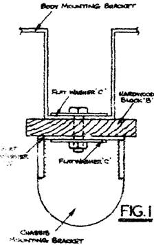
Figure 1. Installation of modified body mounting.
It will be found necessary to provide a slight chamfer on the outside edge of the washers to ensure a flush fit in the body support brackets which are slightly tapered.
3. Cut four hardwood blocks B, Figure 1, 3" x 3" x 7/8" (76.199 x 76.199 x 22.225 mm) and drill a ½" (12.7 mm) hole in the centre of each. Fit the blocks in place of the Silentbloc bushes, ensuring that the grain of the wood is at right angles to the chassis frame, refer to Figure 1.
4. Fit ½" x 2" body mounting bolts with ½" flat washers of 2" outside diameter by 3/32" thick beneath the head of each bolt and fit ½" Oddie nuts together with washers of the previous dimensions, refer to C Figure 1.
Note: The nuts must not be tightened at this stage.
5. Utilize the material shown in Figure 2, i.e. two (2) 'U' bolts (D Figure 2), two (2) hardwood packing pieces (E Figure 2), four (4) stiffener plates (F Figure 2). Fit the parts as shown in Figure 3, to the rear struts and the dash panel, placing stiffener plates f at each side of the dash panel. Fully tighten down the nuts.
Item No. 110. Improved Body Mounting – Jupiter (Continued)
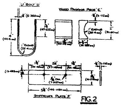
Figure 2. Components for firewall brace – 2 off.
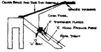
Figure 3. Installation of firewall brace.
6. Tighten the four body mounting bolts.
7. Fabricate from 1" x ¼" strip mild steel bar two (2) side stays (G Figure 4), and weld on two strips of the same material. Fabricate two cross braces (H Figure 4). Bend the side stays to the required shape (see Figure 3) and fit together with the cross braces as shown in Figure 5, using 5/16" bolts (note: 8 mm bolts can be used). Fit 3/8" spacing washers 'I' of 2" (50.799 mm) outside diameter by ¼" (6.35 mm) thick between the side stays and the dash panel assembly (refer to Figures 3 and 5) and a 3/8" flat washer with 2" outside diameter by 1/8" (3.175 mm) thick under the nuts beneath the dash panel.
Note: The holes where the cross braces and side stays overlap at the dash panel should be drilled after the cross braces and side stays have been fitted.
Item No. 110. Improved Body Mounting – Jupiter (Continued)
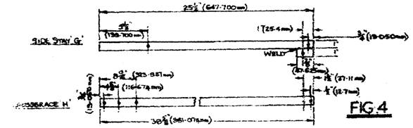
Figure 4. Sketch of side and diagonal stays.
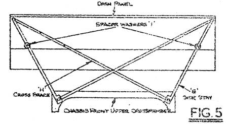
Figure 5. Installation of side and diagonal stays.
8. Reposition the windscreen wiper motor, starter solenoid and horn relay in the most convenient position and blank-off the original mounting holes.
9. Refit the bonnet and front wing assembly.
IMPORTANT NOTE: Use of only the works scuttle bracing without the wooden body mounting blocks renders the car rigid at the scuttle but flexible throughout the body. This can seriously impair its stability, and may in time weaken the aluminium panels by causing excessive flexing. If the scuttle bracing is used, the recommended hardwood blocks should be used instead of rubber for mounting the body.
Budget Locks: It is important to prevent the wings from flapping. Budget locks have been provided at the trailing ends of the wings, but as these can be difficult or time-consuming to do up, they are often left undone. This results in excessive flexing which cracks the wings.
A modification, based on the SC Jupiter solution, is to mount conical rubber buffers on brackets inside the wings. These must register with a carefully positioned hole in the scuttle, so that when the bonnet is shut, the cones press firmly home into the holes, preventing sideways movement.
A metal-to-metal mounting could alternatively be welded on. For example: a 'U' shaped piece of pipe of ½" diameter on the wing , mating with an 'M' section socket bent out of stout (16 SWG) sheet metal welded securely to the scuttle, may be used.
Bonnet Catches: Over-tightening of the bonnet catches causes the aluminium bonnet front to flex, fatigue and crack. Rubber stops are provided for the front of the bonnet to rest on, and these should be kept in good condition and replaced if necessary, when they cease to support the weight of the bonnet without undue tightening of the screw catches.
Bulletin Issue Date: September 1952
Item No. 111. Fitting an Engine Sump Guard – Javelin
Please note: This Item is not complete and is included for reference purposes.
Overseas agents have reported cases that, due to extremely bad road conditions damage is sustained by the engine sump. To prevent this, a sump guard has been designed which can be manufactured and Fitted to cars if so desired. The following instructions and Figures C1, 2, 3 and 4 (not available) will be of assistance in the manufacture and fitting of the sump guard.
1. Remove the bumper bracket frame assembly from the front end of the chassis frame.
2. Fabricate from 5/8" (15.875 mm) by 10 SWG mild steel flat strip a sump guard strap A, Figure C1 and weld to the underneath side of the bumper bracket, see Figure C2.
3. Cut and shape from ¾" (19.050 mm) by 10 SWG mild steel flat strip, two strap stiffeners B, Figure C3, and weld in position as shown in Figure C2.
4. Fabricate from 5/8" (15.875 mm) by 10 SWG mild steel flat strip three strap support brackets C, Figure C4 and weld in position as shown in Figure C2.
5. Apply a coat of paint to the finished assembly and refit to the chassis frame ensuring that the sump guard does not foul the engine sump.
Bulletin Issue Date: December 1952
Item No. 112. Crankshaft Improved Design – Javelin and Jupiter
Further to Bulletin Item Number 104: From Javelin Engine Number E2 PE 22873 and Jupiter Engine Number E2 SC 942, with the addition of the following Javelins: E2 PE 22850, E2 PE 22852, E2 PE 22855 to E2 PE 22864 (inclusive) and E2 PE 22866 to 22871 inclusive, the tolerance of the main bearing journals has been revised from 2.249" – 2.250" (57.025 mm – 57.150 mm) to 2.250" – 2.2505" (57.150 mm – 57.163 mm), and the tolerance of the crankpins from 1.999" – 2.000" (50.775 mm – 50.800 mm) to 1.9995" – 2.000" (50.7873 mm – 50.8000 mm) in order to give improved running clearance. A new rear main bearing, Part Number J54739, has been introduced with this revised tolerance. There has been no alteration to the front main, centre main and connecting rod bearings.
NOTE: The new type rear main bearing must be used only in conjunction with the 'high limit' crankshaft.
Bulletin Issue Date: December 1952
Item No. 113. Cylinder Head Gasket Support – Javelin and Jupiter
From Javelin Engine Number E2 PD 23184 and Jupiter Engine Number E2 SC 948 an improved cylinder head gasket support has been fitted. This support is of cast aluminium and a pre-determined length. No adjustment is necessary to ensure the correct protrusion above the crankcase face, i.e. 0.008" – 0.012" (0.203 mm – 0.304 mm). When fitting the modified support it is necessary to remove the centre cylinder head stud to allow the support to clear the cylinder liner flange.
Bulletin Issue Date: December 1952
Item No. 115. Camshaft End Float – Javelin and Jupiter
From Javelin Engine Number E2 PE 23643 and Jupiter Engine Number E2 SC 957, with the exceptions of the following Javelins:
E2 PE 23805, E2 PE 23811, E2 PE 23813, E2 PE 23816, E2 PE 23817, E2 PE 23829, E2 PE 23837,
E2 PE 23842 and E2 PE 23825, a modified timing case cover, camshaft and thrust peg assembly has been introduced in order to regulate camshaft end float, see Figure 1. The front timing case cover has been modified to incorporate a threaded thrust peg, which is locked in position by a locknut.
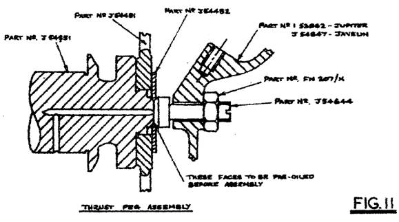
Figure 1. (This is Section AA)
The camshaft now incorporates an integral extension to provide a bearing surface for the adjustable thrust peg. Oil is fed to grooves on this surface via a drilling in the camshaft front journal. To eliminate end float on cars fitted with the foregoing adjustment, release the locknut, Part Number FN 207/K, on the thrust peg and screw in the thrust peg, Part Number J54644, to make light contact with the camshaft, and turn back not more than 1/8th of a turn and tighten the locknut.
During assembly the bearing faces of the thrust plug, Part Number J54824, and the thrust peg, Part Number J54644, must be pre-lubricated.
NOTE: It is most essential that the adjustment is NOT carried out with the engine running.
New part numbers:
Part Number Description
J54644 Thrust Peg
J54451 Camshaft
J54452 Chainwheel Lock Plate
J54824 Thrust Plug
J54647 Timing Case Front Cover (Javelin)
1.52362 Timing Case Front Cover (Jupiter)
FN 207/K Locknut (7/16" BSF)
Item No. 115. Camshaft End Float – Javelin and Jupiter (Continued)
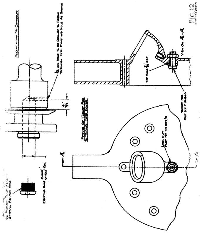
Figure 1 (Continued).
Important Dimensions:
Description Dimension
Existing Bore in Front of Camshaft 0.440" to 0.439"
Oil Drilling from Thrust Face of Camshaft 13/32"
Oil Drilling Diameter 3/32"
Bulletin Issue Date: December 1952
Item No. 116. Oil Pump – Javelin and Jupiter
From Javelin Engine Number E2 PE 23122 and Jupiter Engine Number E2 SC 945, a new type submerged oil pump has been introduced. This modification has been carried out to ensure that the pump is immediately self-priming under all conditions. An adjustable release valve is now incorporated and is pre-set to the correct oil pressure of 65 – 70 psi, and should not be disturbed under any circumstances without first consulting the factory.
The excess oil from the release valve is now returned to the feed side of the pump by an internal drilling. The new type submerged oil pump may be fitted to all engines incorporating the increased flow crankcase.
Bulletin Issue Date: November 1952
Item No. 117. DM2 Distributor – Javelin and Jupiter
When the DM2 type distributor is fitted to an engine it is pointed out that the off-set keyway in the oil pump spindle should be in the position shown in Figure 1, with number one piston at TDC firing stroke.
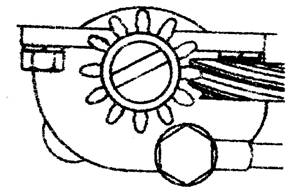
Figure 1. Showing alignment of distributor drive key.
Note: The position of the off-set keyway with number one piston on TDC firing stroke shown in Figure 31on Page 30 of the Javelin and Jupiter Maintenance Manual shows the position when the DKY H4A type distributor only is fitted.
Bulletin Issue Date: December 1952
Item No. 118. Top Water Hose – Javelin
From Javelin Chassis Number E2 PD 22560, the fitting of the rubber hose, Part Number 50751, has been discontinued, and replaced by two rubber hoses joined by an aluminium casting. These parts are fully interchangeable with the previous water hose, as a group.
Bulletin Issue Date: December 1952
Item No. 119. Air Silencer Box – Javelin PE Models
From Javelin Engine Number E2 PE 23320 a cut away has been added to the air silencer box and the oil bath has been given a greater recess in order to give improved clearance for the top water hose. Both the modified air silencer box and the oil bath are interchangeable with the previous type.
Bulletin Issue Date: December 1952
Item No. 120. Tecalemit Oil Filters – Javelin PE Models
It is recommended that the period of change for the Tecalemit oil filter element be set at 5,000 miles (8,000 kilometres).
NOTE: The cleaning of the element is not recommended and is considered to be a dangerous practice. Please make the necessary amendment to all copies of the Javelin and Jupiter Instruction Books in your possession, and kindly notify all owners accordingly.
Bulletin Issue Date: December 1952
Item No. 122. Increased Loading of Synchromesh Springs – Javelin and Jupiter
From Javelin Engine Number E2 PE 23016 and Jupiter Engine Number E2 SC 945R, packings have been added behind the synchromesh springs to increase the spring loading. This is to provide a more positive locking action between the top and third sliding gear sleeve and top and third sliding dog, and first sliding gear and first and second gear sliding dog.
These packings may be fitted to cars prior to the above engine numbers.
Bulletin Issue Date: December 1952
Item No. 123. Swivel Pin Thrust Washers – Javelin and Jupiter
When assembling the stub axles and swivel pins on cars incorporating the rubberised suspension the end float between the swivel pin yoke and the stub axle must not exceed 0.010" (0.254 mm). To enable this adjustment to be made, thrust washers of varying dimensions are available and may be identified by the following part numbers.
Part Number Description Washer Thickness
J54748 Thrust Washer 0.1005" – 0.0995" (2.553 mm – 2.528 mm)
J54749 Thrust Washer 0.1085" – 0.1075" (2.756 mm – 2.731 mm)
J54750 Thrust Washer 0.1165" – 0.1155" (2.985 mm – 2.934 mm)
Bulletin Issue Date: March 1953
Item No. 126. Improved Sparking Plug Cover – Javelin PE Models
From Javelin Engine Number E2 PE 24036, with the addition of the following Engine Numbers E2 PE 24025 and 24026 and the exception of Engine Number E2 PE 24097, an improved type of sparking plug cover has been introduced. The cylinder head top cover has been deleted and the plastic sparking plug cover is replaced by a Lodge type rubber cover, together with a synthetic rubber sealing disc. The Lodge type rubber plug cover is a push-pull fit on the sparking plug and the sealing disc is pushed down into the plug cavity by the pressure of the plug cover.
Existing plug protection arrangements may be converted to this new type by removing the cylinder head top covers and fitting the new type sparking plug covers to the HT leads.
Bulletin Issue Date: March 1953
Item No. 127. Engine and Gearbox Oil Specification
In order to clarify the information given in Bulletin Item No. 121, a list of the lubricants recommended for use in the Javelin and Jupiter engine and gearbox is appended below. Not in this copy.
Bulletin Issue Date: March 1953
Item No. 128. Wheel Tracking
Further to Bulletin Item No. 114, the following is recommended when using the Dunlop optical wheel aligning equipment:
1. The aligning fixture should be located on the tyre side wall.
2. Readings should be taken at two, preferably three, different positions, equally spaced on the tyre side wall circumference, and an average of the three readings taken.
The readings obtained by this method may vary slightly with those obtained using the brake drum face for location purposes (Bulletin Item No. 114) but the error should be within the acceptable tolerances of parallel to ⅛" (3.2 mm) toe-out.
Bulletin Issue Date: March 1953
Item No. 129. Gearbox Ratios – Javelin
From Javelin Engine Number E3 PE 24179, the teeth on the constant mesh drive gear were decreased from 19 to 18. The teeth on the layshaft cluster constant mesh drive gear were increased from 33 to 34. This alteration was introduced at gearbox number 8153 and it gives a lower gearbox and overall gear ratio as detailed below:
Drive Ratios from Engine Number E3 PE 24179
Gearbox Ratio Final Drive Ratio
Top 1 to 1 Top 4.875 to 1
Third 1.5 to 1 Third 7.340 to 1
Second 2.38 to 1 Second 11.60 to 1
First 3.88 to 1 First 19.00 to 1
Reverse 3.88 to 1 Reverse 19.00 to 1
Drive Ratios from Engine Number E0 PC 11270 to E3 PE 24179
Gearbox Ratio Final Drive Ratio
Top 1 to 1 Top 4.875 to 1
Third 1.37 to 1 Third 6.700 to 1
Second 2.17 to 1 Second 10.60 to 1
First 3.56 to 1 First 17.40 to 1
Reverse 3.56 to 1 Reverse 17.40 to 1
Bulletin Issue Date: March 1953
Item No. 131. Tappet Adjustment, Solid Type – Javelin and Jupiter
To clarify the instructions on tappet adjustment the following notes are issued. It is extremely important in view of the fine adjustment required that:
1. With the engine COLD the inlet clearance is set to 0.003" (0.076 mm) and the exhaust to 0.006" (0.152 mm) these dimensions being measured between the end of the valve stem and the rocker.
2. Ensure that the tappet being adjusted is riding on the base circle of the cam and NOT on the initial portion of the cam-quietening ramp.
These are two methods of obtaining the above conditions:
a) Adjustment should be made to tappets according to the table shown below:
Setting Position of Engine Valve to be Adjusted
Number 1 Exhaust valve fully open Number 2 Exhaust
Number 1 Inlet valve fully open Number 2 Inlet
Number 3 Inlet valve fully open Number 4 Inlet
Number 3 Exhaust valve fully open Number 4 Exhaust
Number 2 Exhaust valve fully open Number 1 Exhaust
Number 2 Inlet valve fully open Number 1 Inlet
Number 4 Inlet valve fully open Number 3 Inlet
Number 4 Exhaust valve fully open Number 3 Exhaust
See chassis number plate on bulkhead to identify cylinder numbers.
b) The alternative is to deal with each valve individually. Obtain the fully open position of the valve, and then turn the crankshaft through one complete revolution; this will bring the valve in question to the fully closed position with the tappet on the base circle directly opposite the peak of the cam.
Bulletin Issue Date: March 1953
Item No. 132. Sparking Plug Threads – Javelin and Jupiter
Where cases of 'running on' are encountered and all standard methods of eliminating this fault are ineffective, the cause is probably due to uncovered sparking plug cavity threads becoming red hot. These threads have now been modified to eliminate any exposed threads after the sparking plug has been tightened down.
When this point is encountered on existing heads the following action should be taken: Screw in an old sparking plug of the correct type, that is Champion L10 for Javelin and L10S for Jupiter, then using a small grind stone on a flexible drive, remove the threads which remain exposed to view. The aim is to get as close to the end of the sparking plug's base as possible.
Bulletin Issue Date: March 1953
Item No. 133. Wheel Tracking – Javelin and Jupiter
The following is recommended when using the Dunlop optical wheel aligning equipment:
1. The aligning fixture should be located on the tyre side wall.
2. Readings should be taken at two, preferably three, different positions, equally spaced on the tyre side wall circumference, and an average of these readings taken
The readings obtained by this method may vary slightly with those obtained using the brake drum face for location purposes but the error should be within the acceptable tolerances of parallel to 1/8" (3.2 mm) toe out.
Bulletin Issue Date: March 1953
Item No. 134. Bad Starting on Javelin and Jupiter Engines
Reports have occasionally been received of bad starting. Our investigations show that this complaint is invariably traced to one or a combination of the following faults:
1. Loss of compression on one or more cylinders due to insufficient tappet clearance.
2. Choke strangler flaps not closing fully (Modern Note: Set the LHS choke strangler flap to close fully slightly in advance of the RHS choke strangler flap. The natural spring twist in the actuating cross rod will permit the RHS choke strangler flap to fully close, thus ensuring that both flaps are fully closed. This instruction applies to right hand drive cars.)
3. Incorrect fast idling adjustment.
4. Failure of immediate fuel supply to carburettors.
5. Incorrect ignition timing.
6. Faulty ignition system.
7. Battery charge low.
8. Engine requires de-carbonising.
When dealing with cases of this nature, it is recommended that the following procedure is adopted. (None available yet.)
Bulletin Issue Date: March 1953
Item No. 135. Improvement to Reverse Lock Lever – Javelin and Jupiter
Cases of the gearbox sticking in first gear usually after reverse gear has been used have been traced to the long arm of the reverse selector lock lever, Part Number J50140, catching on the first gear selector fork.
To eliminate this fault remove approximately 1/16" (1.6 mm) from the reverse selector lock lever and back off as shown in Figure 1.
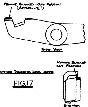
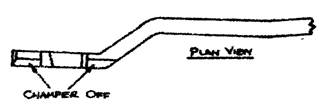
Figure 1 Modification to reverse selector lock lever.
Bulletin Issue Date: May 1953
Item No. 136. Identification of Replacement Engines
Replacement engines embodying partial Series III components are now being fitted with an identification plate. This plate is located at the top right hand side of the engine (looking from front to rear) between the tappet cover and the clutch housing. (Immediately inboard of the starter bendix.)
This plate gives the reconditioned engine number, main bearing size, the thickness of the rear thrust washer plus the thickness of the shims which may have been added to obtain the crankshaft end float, and the cylinder bore size.
Bulletin Issue Date: May 1953
Item No. 137. Cylinder Head Studs – Javelin and Jupiter
In order to reduce the possibility of the crankcase being damaged when cylinder head studs are being fitted the following modification was introduced at the under mentioned engine or crankcase numbers:
Engine Numbers E3 PE 24111 – 24113 to 24128 inclusive 24136 – 24137
Crankcase Numbers 25475-25479-25486-25579-25624-25632-25749-25888-25894-25898-25904- 25911-25916-25918-25955-25982-25989-25998-256004-26007-26011-26017-26039-26049-26060-26063-26072-26087-26088-26120-26129-26436-26496 and onwards.
The modified crankcases may be identified by the small holes drilled in the underside of the block at each corner; these run into the cylinder head stud holes and act as release holes.
The crankcase also incorporated a deeper counter bore for the long cylinder head studs. In consequence these studs have been increased in length. The previous stud, Part Number 50637, being 4.5625" (115.89 mm) long and the modified stud, Part Number 54768, being 4.75" (120.65 mm) long.
Bulletin Issue Date: May 1953
Item No. 138. Method of Identifying Series III Crankcases – Javelin and Jupiter
On the earlier Series III crankcases the crankcase was identified by the letters 'PE' stamped on the front left hand portion of the crankcase, between the crankcase set number and the engine number, as described in Bulletin Item Number 107. Later this method was changed to the stamping or casting of a '3' on the crankcase adjacent to the front timing case rear cover.
Bulletin Issue Date: May 1953
Item No. 139. Camshaft Conversion – Javelin and Jupiter
In order to convert the pre-Series III type camshaft to the Series III type detailed Bulletin Item Number 115 (Page ??), the following action should be taken (refer Figure 1, Bulletin Item 115):
1. Remove the camshaft and drill a 3/32 (2.38 mm) diameter hole in the front camshaft journal to break into the existing hole at right angles. The position should be 13/32" (10.32 mm) to the rear of the camshaft thrust face.
2. Press the camshaft end plug, Part Number J54824, into the 0.440" – 0.439" (11.18 – 11.15 mm) diameter hole already in existence in the camshaft end.
3. Tap the timing case cover with a 7/16" BSF thread as shown in Bulletin Item 115. The hole in the timing case cover at present should be a suitable size for tapping out.
4. Fit the thrust peg, Part Number J54644, and locknut, Part Number FN 207/K, to the timing case cover. Reassemble after pre-oiling the end plug and thrust peg bearing faces.
5. With the engine STOPPED adjust the camshaft end float by screwing the thrust peg into light contact with the camshaft end plug and slacken back not more than 1/8th of a turn, then tighten the locknut.
Bulletin Issue Date: May 1953
Item No. 140. Conversion of Suspension to Rubber Bushed Type – Javelin and Jupiter
It is possible to convert the old metal-bushed suspension to the new type rubber front suspension by using the following late type parts:
Part Number Qty. Description Part Number Qty. Description
J54466 4 Upper Spring Arm J54467 2 Upper Spring Arm Pin
J54491 4 Metalastik Bush FB 107/27 2 Bolt, Clamping Upper Arm
FN 107/K 4 Nut J54449 1 Upper Link Bracket (LHS)
J54490 12 Metalastik Bush J54448 1 Upper Link Bracket (RHS)
54082 1 Stub Axle (LHS) 52084 A/R Upper Link Bracket Shim
54083 1 Stub Axle (RHS) 54023 A/R Upper Link Brkt. ½ Shim
50275 4 Stub Axle Bush J54450 2 Spindle Upper Link Brkt.
J54475 2 Swivel Pin J54474 4 Upr. Link Trunnion Washer
J54476 2 Swivel Pin Yoke J54509 2 Swivel Pin Thrust Washer
52591 A/R Shim, Swivel Pin 50571 4 Grease Nipple
54087 2 Locking Ring 54088 2 Locking Ring Peg Screw
54091 2 Hub Joint (Gasket) W 10 2 Washer
FN4 10/K 2 Slotted Nut 190/S 2 Front Hub Bearing (Outer)
54085 2 Distance Tube 189/S 2 Front Hub Bearing (Inner)
54084 2 Oil Seal (Inner) 54086 2 Corner Spacer
54090 2 Grease Cap 50697 6 Set Screw, Grease Cap
FB 104/14 2 Bolt ¼"x 1¾" BSF J54485 2 Lower Spring Arm Pin
J54473 2 Spring Arm Washer J54468 2 Spring Arm Pin Spacer
J54470 2 Front Shock Absorber 52151 8 Bush Thimble, Shock Abs.
50469 8 Shock Absorber Bush FB 107/26 2 Bolt, Shock Absorber
FN 107/K 4 Shock Absorber Nut J54472 4 Washer, Pin Support
J54494 4 Spacer, Shock Abs. J54495 4 Keeper Plate
W7 4 Washer FB 107/17 2 Shock Absorber Bolt (Lwr)
FS 104/4 4 Setscrew, Keeper Plate
It is essential that if this conversion is carried out on a Javelin before Engine Number E0 PB 10594, that the stub axle, together with the complete brake and hub assembly are retained, or if they require replacement, they are replaced by the same type.
Bulletin Issue Date: May 1953
Item No. 141. Balance Pipe Seal Test – Javelin and Jupiter
If on carrying out the balance pipe seal test it is found impossible to hold the requisite amount of vacuum, the following action should be taken. Retain the test equipment in position but remove vacuum gauge and plug the adaptor to which it was fitted. Apply a pressure pump in place of the vacuum pump and put the system under pressure. Whilst the system is under pressure spray oil onto all joints and pipes in the system. Determine where the leak is occurring by observing the point at which the oil is affected by the escaping air pressure. This point should then receive attention.
Bulletin Issue Date: May 1953
Item No. 142. Schedule of Labour Times
Engine Man Hours Remarks
Replace new engine 7 This includes transfer of components
Replace reconditioned engine 8 This includes transfer of components
Tune engine 2
Re-set ignition ½
Replace engine mountings 1½ Both sides
Replace near-side tappets 2½ 1 hour extra if oil cooler fitted
Replace off-side tappets 2
Replace rocker assembly 1
Replace rocker arm (inlet) 1½ Off-side 1½ (1 hr. extra where oil cooler fitted)
Replace all near-side push rods 2 Off-side 1½ (1 hr. extra where oil cooler fitted)
Replace 1 or all push rods 1 side 2 I hour extra if oil cooler fitted
Replace camshaft (comp op) 6
Replace timing chain 3
Replace oil pump drive gear 3½
Re-time camshaft 4
Adjust tappets both sides 1½
Replace camshaft chainwheel 3
Replace near-side cylinder head 2½ Off-side 2 hours
De-carbonize and grind in valves 12
Fit new valve or valve spring n-s 3 Off-side 2½ hours
Fit new valve guide (near-side) 3½ Off-side 3 hours
Bulletin Issue Date: May 1953
Item No. 143. Gearbox Ratios – Javelin
Further to Bulletin Item 129, on the introduction of a wider gearbox ratio. This was introduced at gearbox Serial Number 8153.
Bulletin Issue Date: May 1953
Item No. 144. Improved Method of Sealing Oil Galleries – Javelin and Jupiter
At the following engine and crankcase numbers:
Engine Numbers:
E3 PE 24111-E3 PE 24113 to E3 PE 24128 inclusive, E3 PE 24131- E3 PE 24136- E3 PE 24137- E3 PE 24142- E3 PE 24159- E3 PE 24165- E3 PE 24178.
Crankcase Numbers:
25475-25479-25486-25597-25624-25632-25749-25888-25894-25898-25804-25911-25916-25918-25955-25982-25989-25998-26004-26007-26011-26017-26039-26049-26060-26063-26072-26087-26088-26120-26167-26436-26496 and onwards.
A counter bore has been added to the oil galleries and a new type of gallery plug has been fitted. The plug cannot be fitted to the unmodified crankcases.
Bulletin Issue Date: August 1953
Item No. 149. Liner Bottom Seal – Javelin and Jupiter
A synthetic rubber cylinder liner seal was fitted to certain engines. Their number or crankcase number is listed below:
Engine Numbers: E3 PE 24111, E3 PE 24113 to E3 PE 24139 (inclusive).
Crankcase Numbers: 25394, 25475, 25479, 26039, 26049, 26053, 26055, 26060, 26070, 26072, 26087, 26088, 26111, 26120, 26129, 26157, 26436, 26500 to 26509 (inclusive), 26520, 26521, 26526, 26541, 26545, 26546, 26547, 26549, 26550, 26551 and 26573.
This seal consisted of a synthetic rubber sealing ring trapped in a chamfer machined in the crankcase, the cylinder liner thus making metal to metal contact with the crankcase, eliminating the necessity of fitting copper shims as used with the standard type to obtain the correct liner protrusion above the face of the cylinder block. On the engines with the rubber type bottom seal the following parts are different and are not individually interchangeable with the standard arrangement:
Part Number Description Qty.
J54708/9 Crankcase set (1 LH & 1 RH) 1
J54706 Cylinder Liner 4
J54707 Cylinder Liner Sealing Ring 4
![]()
Bulletin Issue Date: August 1953
Item No. 154. Modified Horn Pick Up Brush – Javelin and Jupiter
The horn pick up brush has been modified to the design shown in Figure 1.
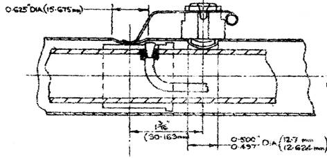
Figure 1. Arrangement of modified horn pick up brush.
The existing steering column can be modified to incorporate the latest horn brush by drilling the additional hole show in Figure 1, and fitting the new pick up brush assembly, Part Number J54733/A, and using the existing clip.
Bulletin Issue Date: August 1953
Item No. 155. Modified Reverse Lock Lever – Javelin and Jupiter
A reverse lock lever of thicker gauge material and revised dimensions has been designed. As yet, only a limited quantity of these have been produced and fitted to gearboxes going into the American market. When this feature becomes general production, the engine or gearbox number will be issued.
The modified lever, Part Number J54800, is interchangeable with the previous type, Part Number 50140, if the previous type reverse link pin, Part Number J50112, is replaced by the modified type, Part Number J54801.
Bulletin Issue Date: May 1953
Item No. 156. Introduction of Jupiter Cylinder Head on Javelin Engines
From Engine Crankcase Number 26526 the Jupiter cylinder head was introduced as standard on the Javelin engine.
Previous Javelin engines may be fitted with this cylinder head provided the water transfer and push rods are changed for the Jupiter type.
Bulletin Issue Date: November 1953
Item No. 158. Changes in Shock Absorbers – Javelin all Models
The part numbers in brackets in the table below are the manufacturers' assembly numbers:
Engine Number Part Number (Front) Part Number (Rear) Remarks
From D8 PA 8 50468 (01314) 50467 (0115A) Original Units
To D9 PA 4381
From D9 PA 4382 52584 (01314) 50467 (0115A) Rebound Buffer Modified
To E0 PB 9876 on Front Units
From E0 PB 9877 54010 (02395) 50467 (0115A) * Redesigned Lower
To E1 PC 16499 Attachment on Front Units
From E1 PC 16500 54385 (02748) 50467 (0115A) ** 25% Increased Strength
To E2 PD 21867 of Front Units
From E2 PD 21868 Ref. Bulletin Item No. 97
To E2 PE 22345
From E2 PE 22346 CD 9079 (03025) 54383 (02749) *** Competition Unit Front,
Onward Bump Stops in Front Unit
* Service Bulletin Item Number 29
** Service Bulletin Item Number 54
*** Service Bulletin Item Number 108
Bulletin Issue Date: November 1953
Item No. 159. Axle Shaft Nuts – Javelin and Jupiter
The threads on the axle shaft and the axle shaft nuts of the Javelin and Jupiter axles have now been changed from BSF to SAE threads (14 TPI).
The corresponding new part numbers are:
Axle Shaft Part Number 3MA-005-21 SAE Threads
Axle Shaft Nut Part Number 14A-74-11 SAE Threads
The axle shaft extractor, Part Number J14836, will not fit these new thread forms, but steps are being taken to make a suitable adaptor for fitting the above tool.
Bulletin Issue Date: November 1953
Item No. 162. Spring Arm Conversion – Javelin and Jupiter
Further to Service Bulletin Item Number 140, a scheme has now been evolved whereby the front spring arms fitted to pre-rubber bushed suspensions on cars before Javelin Engine Number E2 PD 21868 and Jupiter Engine Number E2 SA 865, may be modified and used with the rubber bushed suspension.
Reference should be made to Figures 1a, b and c for conversion instructions. Figure 1a shows the general arrangement, Figure 1b and Figure 1c show the parts required to convert the spring arm.
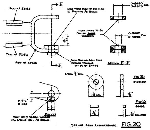
Figures 1, 1a, 1b and 1c. Front spring arm conversion (RHS shown).
Parts Required to Convert the Spring Arms:
Part Number Qty. Description Part Number Qty. Description
J54480 2 Spacer (Fig. 1b) J54492 2 Stop (Fig. 1c)
Bulletin Issue Date: November 1953
Item No. 163. Engine Overheating and Pinking – Javelin and Jupiter
Cases have occurred where engine overheating and pinking has been caused by a restriction between the outer wall of the cylinder head and the cylinder head stud hole casting shown in Figure 1.
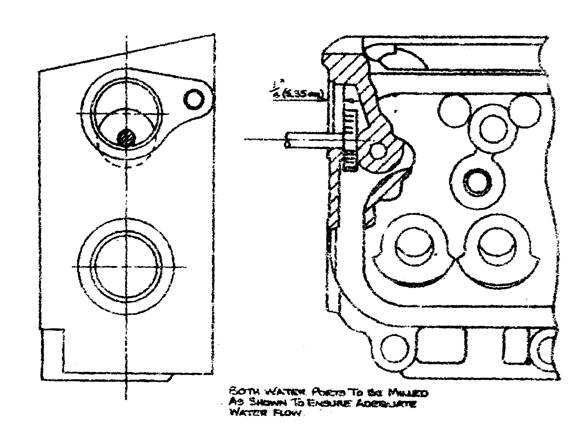
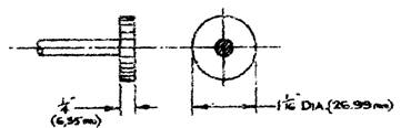
Figure 1. Showing where material can be milled from cylinder head.
In cases of this nature an adequate water flow between these two points can be ensured by inserting a Woodruff cutter as shown in Figure 1 through the cylinder head water port, Figure 1, and milling a ¼" (6.330 mm) passage between the cylinder head outer wall and the stud hole casting.
Bulletin Issue Date: November 1953
Item No. 164. Front Hub Bearings Conversion Scheme – Javelin and Jupiter
It is advised when replacing front hub bearings to use the Service Replacement Scheme now in operation.
This scheme involves the changing of the inner bearing, which is of the ball type, to a roller bearing, Part Number J54855 (Skefco CRL 8), and also the distance piece to the new type, Part Number J54854. When fitting the new bearing, attention must be paid to the dimensions required when pressing the roller bearing into position, refer to Figure 1. The outer ball bearing, Skefco RMS/6, remains unchanged.
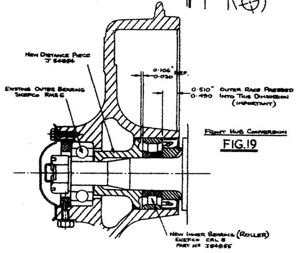
Figure 1. Arrangement of roller bearing conversion.
The roller type bearings and distance piece can be fitted to all hubs after Engine Number E0 PB 10594 (Javelin) and Engine Number E0 SA 56 (Jupiter), the new type distance piece must be used.
Bulletin Issue Date: November 1953
Item No. 166. Camber Setting – Javelin and Jupiter
In cases where the frame level gauge, Tool Number J.9127C, is not available, steering camber should be carried out as follows:
With the car on level ground adjust torsion bars until frame height from underside of frame to ground is 10" (254 mm). A plumb line is then dropped from the tyre as near to centre as possible, care being taken to avoid the tyre bulge and the distance between plumb line and tyre should measure 1/16" (1.59 mm).
To obtain correct dimensions, adjustment can be made by means of shims, Part Number J54731, fitted between the upper link bracket and the frame.
After setting the camber the overall wheel track should be checked.
Bulletin Issue Date: November 1953
Item No. 167. Crankcase Breather Valve – Javelin and Jupiter
To assist with the many enquiries regarding the crankcase breather valve, the following details are issued.
The crankcases of both the Javelin and the Jupiter are designed to operate at a pressure slightly below atmospheric pressure (14.7 psi), the normal running pressure in the crankcase being between 14 – 14.6 psi. To ensure even running of the twin carburettors a balance pipe was fitted from which runs a connecting pipe to the oil filler tube where the breather valve is located. To further assist the circulation of the air, breather vents are fitted one in each push rod cover, inside which, is tucked a small felt to act as an air filter. (Refer to Bulletin Item 9)
It is advisable to note the necessity of keeping the felts clean, as neglect of this point may cause failure of the petrol pump (Javelin) and bad engine performance.
When the engine is on tick-over or closed throttle, the pressure in the crankcase is 14 – 14.6 psi whilst in the balance pipe the pressure is approximately 8 – 10 lbs per square inch, and in this circumstance the breather valve is closed with the exception of the small airflow, which is consistent through the small toggle valve B, Figure 1.
If the breather valve was not closed and a free passage of air allowed from the crankcase to the balance pipe, the slow running mixture would be varied resulting in rough tick-over, engine hunting, excessive petrol consumption and flat spots on the initial take off.
It is therefore essential that the breather valve is closed on the tick-over or closed throttle. See Figure 1.
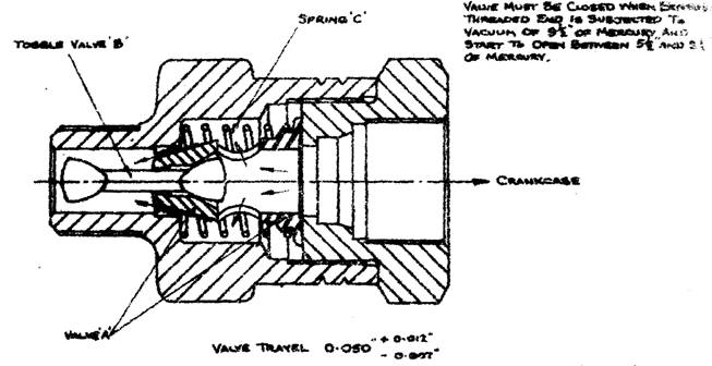
Valve must be closed when breather threaded end (connected to balance pipe) is subjected to 9½" of mercury and start to open between 5½" and 3½" of mercury.
Figure 1. Section through breather valve.