INTRODUCTION
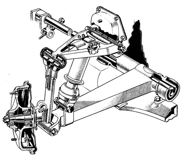
The torsion rod front suspension in the Jowett Javelin has the
torsion rods arranged longitudinally, one on each side of the car. The rods
have octagonal ends that are a press fit into female octagonal bores in the
front spring arms, and chassis frame mounted anchors to the rear. The torsion
rods are pressed into the front end of the spring arm trunnion bushing.
At the rear of the torsion rods there is a ground clearance adjustment
facility. The adjustment is made by a long-thread bolt that is threaded into a
trunnion that fits into an arm pressed onto the rear of the torsion rod. The
long-thread jack bolt features a machined spigot that locates into a chassis
frame mounted pad.
The torsion rods are not the only
suspension medium, the front spring arm trunnion bushes are of the Metalastik
type, with the inner sleeve a press fit onto the spring arm trunnion bushing.
The outer sleeve is a press fit into the front bracket housing, and at the
rear, it is clamped into the chassis mounted bracket. The torsion bar passes
through the spring arm trunnion bushing.
REMOVING AND REFITTING THE FRONT TORSION RODS
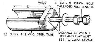
The torsion rod can be removed with the minimum of dismantling using
a special puller. This puller is made up from 1 5/8" 8 SWG tube 3
3/8" long. The tube has one side cut longitudinally to provide clearance
for the chassis frame. A substantial 'D' shaped end cap with a 7/16"
clearance hole in the centre of the diameter is welded on to the tube. The
distance between the flat edge of the 'D' and the edge of the hole must be
5/16" to provide clearance at the chassis frame. A 7/16" BSF all
thread rod is threaded into the end of the torsion rod. A jam nut can be used
to lock the rod. A nut and plain washer are used to draw the torsion rod out of
the front spring arm and the rear adjustment lever.
Park the car on a firm level surface and apply the hand brake. Jack
up the front of the car until the wheels are clear of the ground. Place chassis
frame on suitable stands. Remove the battery and disconnect the midship bearing
support from the frameside, on the side from which the torsion rod is to be
removed.
Slack-off the torsion rod adjustment completely and remove the rear
locating plate. Place the torsion rod puller in position against the bracket on
the frameside at the rear end of the torsion rod and insert the all-thread rod
into the tapping at the rear end of the rod. Draw the rod clear of the octagons
in the normal manner. Remove the torsion rod to the rear, driving the front end
octagon through the adjusting lever.
When refitting set the spring arm against the rebound rubber, and
the adjusting lever against the frameside, smear the octagonal ends with
graphite oil (Loctite Antisieze or Penrite Copper-Eze) and drive the torsion
rod ends into position. Make sure that the torsion rod is refitted in the same
orientation as it came out. Take special care to guide the front end into
position, and to make absolutely certain that the rod suffers no surface
damage.
The rod should of course be fitted with the tapped end at the rear.
The locating plate should now be fitted, and the adjusting bolts set
so that both frameside members are 9¾" to 10" (248 – 254 mm) clear
of the ground at the gearbox cross member. (Refer to Torsion Rod Adjustment
section.)
Note: If the torsion rod puller is not readily available the rod can
be removed by driving out to the front, after removing the front apron,
disconnecting the front engine mountings and jacking the engine slightly so
that the cylinder blocks are clear of the torsion rod line. The rod can also be
refitted from the front with the engine in this position.
It is important to understand that it is very likely that the
torsion rods have been in situ for more than fifty years. If the vehicle has
been standing for long periods in damp conditions, the rod ends may be frozen
in their mating components. In severe cases, twenty tonnes or more may be
required to shift the torsion rod.
It must be appreciated that, while
considering the above condition, attention is drawn to the section on Handling
and Storage of Torsion Rods.
TO REMOVE AND REPLACE THE FRONT SPRING
ARMS
To remove a front spring arm, slack-off all of the torsion rod
adjustment. Place a jack under the outer end of the spring arm and raise the
arm so that the rebound buffer rubber can be removed. Lower the spring arm
until it is completely relaxed.
Remove the spring arm pin (special bolt) and the distance tube
securing the lower end of the swivel pin (king pin) and stub axle assembly.
Remove the bolt securing the lower end of the shock absorber. Support these
suspension components away and above the spring arm. Take care not to damage
the brake hoses.
Slack-off the clamp bolt at the rear of the spring arm trunnion, and
detach the bracket from the frameside at the front end of the trunnion. Draw
the torsion rod clear of the spring arm as described in Removing and Refitting
the Front Torsion Rods. Draw the spring arm forward, clear of the rear clamp,
and lift out.
Alternatively, if the engine has already been removed from the
chassis, the torsion rod and spring arm can be removed together, by detaching
the spring arm as described above, removing the rod locking plate, driving the
torsion rod clear of the rear end octagon, and drawing the rod and spring arm
forward until clear of the chassis.
Check the outer end of the spring arm for excessive wear on the
swivel pin and shock absorber drillings, and for any possible distortion. It
should be noted that wear will occur only if these bolts have ever been loose.
Check the Metalastik trunnion bushes for wear or oil damage and, if
necessary, drive the front spring arm bracket and bush assembly from the front
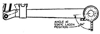
end of the trunnion, and press out the worn bush. Press the replacement bush
into the bracket, and press the bracket assembly on to the spring arm trunnion
so that the face of the larger of the two arms on the bracket is at
approximately 80° to the line
of the spring arm.
Note: The diagram below shows angle in the approximate static load
condition, indicating the increased angle of 84°, due
to vehicle's weight being carried.
Drive or chisel off the bush at the rear of the trunnion and press
on the replacement, with the flanged end to the front. The spring arm trunnion
bushes should be replaced in pairs on the spring arm.
Prior to commencing re-assembly, the chassis frame should be
carefully examined for cracking in the spring arm mounting areas. Should
welding be required, then the torsion rods should be removed completely and
kept well away from the welding process.
To re-assemble, reverse the routine outlined for dismantling, with
special attention to the following points:
1. The swivel pin and distance
tube must be settled correctly in the outer end of the spring arm, so that the
suspension movement is free.
2. The
swivel pin bolt should be installed with its head facing the rear. It should be
tightened down so that maximum steering lock is achieved when the back plate
bolt head contacts it.
3. Shock
absorber bushes and thimbles should be examined for wear and replaced if
necessary.
4. Prior
to adjusting the torsion rod, jack up the spring arm and replace the rebound
buffer.
5. Set
the chassis ground clearance.
6. Re-tighten
the hardware after 500 miles have been covered.
On later type front suspension, the
above instructions generally apply. Rubber bushes are fitted at the base of the
swivel pin.
FRONT TORSION ROD ADJUSTMENT
The following method should be adopted for setting the chassis
height (ground clearance), by adjusting the torsion rod tension.
Stand the car on level floor, and measure the distance from the
underside of each frameside to the floor. The measurements should be taken at
the front of the gearbox cross member.
Set the tyre pressures to 26 psi (180 kPa).
Jack up the car, using a trolley jack under the centre of the
gearbox cross member, until the wheels are just clear of the ground. It is
important that a wooden protection pad should be placed on the jack pad, to protect
the frame member.
Slack-off the location plates at the rear end of the torsion rods,
and slack back the lock nuts on the adjuster.
Lubricate the adjuster long-thread bolt, its spigot, the pad in its
trunnion, the adjuster arm in its bracket and the threaded trunnion in the arm.
If these components are not free to move and are not lubricated, there will be
excessive strain imposed upon then while the adjustment is made. Such loadings
can cause wear at the long-thread bolt spigot.
Reset the adjuster as necessary, in relation to the measurements
previously taken, to obtain a ground clearance of 9¾" – 10" (248 –
254 mm) at each end of the gearbox cross member. Lower the car to the ground
and bounce on its suspension and check the measurements again. Jack up and make
the final adjustments if necessary. Re-tighten the torsion rod end plates and
tighten the adjuster bolt lock nut.
In isolated cases it may be found that
the specified dimension for ground clearance cannot be obtained due to
excessive wear on the adjusting bolt spigot or thread. This is normally caused
by adjusting with the weight of the car on the road wheels, and it will be
necessary to either build up the spigot or replace the bolt. It should be noted
that no wear takes place once the adjusting bolt is in position.
HANDLING AND STORAGE OF TORSION RODS
The torsion
rods were manufactured to very close tolerances, the octagons were milled and
the shank length was very finely finish ground. Because of this, great care
must be taken when handling torsion rods.
Jowett Cars Limited requested that torsion rods be stored on felt
lined racks, with indentations to ensure that the rods could not come into
contact with each other during storage. When handling the rods, make sure that
they are not struck in any way likely to cause damage to the surface. A very
slight and small scratch can weaken a torsion rod and exceptional care should
be taken when handling.
Should surface damage occur, the torsion rod should be replaced at
the earliest opportunity.
All of the foregoing seems a bit incongruous when it is considered
that, installed in the car, the torsion rods are exposed to stones thrown up by
the road wheels and to rust due to water thrown up at them. To date the writer
is not aware of a torsion rod actually breaking due to road or rust inflicted
damage. However, it is very well known that if a minute weld spatter lands on a
torsion rod, the rod will soon break at that point. The same applies should
there be an inadvertent nick ground in by a wayward angle grinder disc.
The Jowett Car Club of Australia does not have many second hand
torsion rods in stock. Therefore, great care has to be taken with those that
remain.
If storing
second hand torsion rods, it is a good idea to label each one with details of
where on the car it was located. The Jowett torsion rod is a very long life component,
and if treated with the care and respect it deserves, will last for many years.
The specification of the torsion rod spring is as follows:
Material Silicon
manganese spring steel
Length 36"
(914.4 mm)
Diameter 0.880"
(22.352 mm)
Spring
periodicity 69 cycles/minute at normal load
Working
load 846 lb (383.8 kg)
Normal load 652 lb (295.8 kg) on spring arm
Stress 30.96
tons per square inch at load of 652 lb
Stress 52.24
tons per square inch at full bump
FRONT SPRING ARM HARDWARE – WARNING!
Many
Javelins have been lost to scrap because of rust problems in the front floor
area. This is quite a complex concern because it involves the front spring arm
mounting hardware. The frame sections where the front spring arms bolt on can,
if the securing hardware is neglected, crack and permit water to enter the complex
hollow section. Once the water has entered, it runs rearward down to the front
floor/bulkhead area where it is trapped and causes corrosion.
There is a
long bolt which goes through the spring arm bracket and frame vertically. This
bolt can be found to be loose, being in a not easily seen position and, each
time the front suspension moves violently the shock is transferred, to the bolt
and then down the frame where it quickly breaks the rust weakened frame. Once
broken, there is very little that can be done. Because of the complex
construction at this point, it is extremely difficult to repair.
The
importance of keeping this key bolt tight cannot be overstressed enough. The vertical spring arm bolt passes through the sheet metal of the
box section of the frame member. There is a distance tube welded into the
structure, which takes the clamping load when the bolt and nut are tightened
down.
Re-tighten
the front spring arm hardware after 500 miles have been travelled since
hardware installation.
Note: The
Jowett Car Club of Australia does hold limited stock of chassis extension arms
and the jigs for welding them into the car.
Prepared by Mike Allfrey.