TECHNICAL NOTES SERIES
JOWETT JAVELIN Ė PA, PB, PC, PD & PE
JOWETT JUPITER Ė SA & SC

PART XVIII Ė ZENITH CARBURETTOR
The Jowett Car Club of Australia Incorporated is not responsible for any inaccuracies or changes that may occur within this document. Every effort has been made to ensure total accuracy. It is not a Jowett Car Club publication and, therefore, the Club has no control over its contents. These Technical Notes have been compiled by using the latest information available.
Compiled by Mike Allfrey.
January, 2007.
THE ZENITH V-TYPE DOWN-DRAFT CARBURETTOR
This carburettor is made in several models; the general principles are the same for all of these models, which differ only in detail design, dimensions and arrangement. Figure 1. shows the Zenith Type 30VM in diagrammatic cross-sectional view. This model was used on Jowett Javelin and Jupiter motorcars in the types 30VM-4 (early Javelin), 30VM-5 (later Javelin models) and 30VM (very late production Jupiter and Javelin models). The early model Jupiter used Zenith 30VIG-5 carburettors, which are essentially the same as the Zenith types described here. The major difference is that the Zenith 30VIG-5 carburettor features an accelerator pump to boost the amount of petrol entering the choke tube while the throttle plates are opened. Jowett Cars Limited were amongst very few manufacturers who used the Zenith V type of carburettor in pairs, and they were very likely the only vehicle manufacturer who placed the carburettors directly onto the cylinder heads.
Referring to Figure 1. at Item 3, a shroud is illustrated. This shroud was only used on 30VM type carburettors (very late production Jupiter and Javelin models).
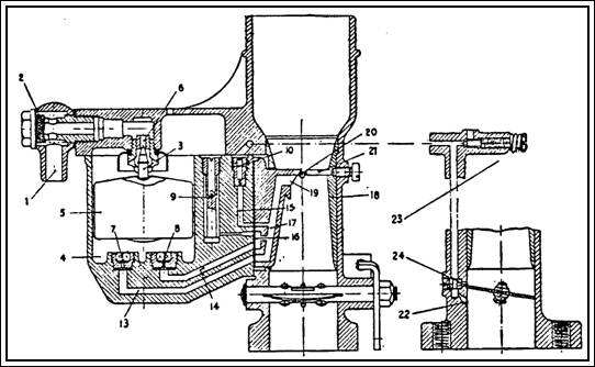
Figure 1. Sectional views of the Zenith Type-30VM carburettor.
Major Components: 1, Petrol Union. 2, Filter Gauze. 3, Needle. 4, Float Chamber. 5, Float. 6, Needle Seating. 7, Main Jet. 8, Compensating Jet. 9, Capacity Tube. 10, Slow Running Jet. 16, Emulsion Block. 18, Choke Tube. 20, Distributor Bar. 21, Choke Screw & Third Bar. 23, Slow-running Air-adjustment Screw. 24, Progression Jet. †
The Zenith Type 30VM-4 carburettor the capacity tube, Item 9, Figure 1, does not feature the separate screwed in capacity tube Ė it was a direct drilling to size. Consequently the choke screw, Item 21, Figure 1, is not required in the 30VM-4 carburettor. The 30VM-4 carburettor was used on Javelins to D8 PA 1753, it was also used on the Austin A40 of the same period.
Normal Operation: Referring to Figure 1, with the throttles closed down to the low idle position the mixture will be supplied from the slow-running jet, Item 10. Depression will be concentrated upon the outlet, Item 22, and will, in turn, be directed on to the slow-running jet, Item 10. Here there is a controlled depression fall because of the leak at the slow-running air-regulating screw, Item 23. Air is also being drawn in through the progression jet, Item 24.
Petrol will be drawn from the well, Item 15, beneath the jet and measured on passing through, before continuing to the throttle edge. At the throttle edge there is a further outlet, Item 24, which breaks into the slow-running passage. Upon the throttle being opened from the low idle position depression will be concentrated here and a progressive getaway from slow running is assured.
The depression at this throttle position is drawing petrol and air through both outlet, Item 22, and the progression jet, Item 24. This is now a rich mixture which, when mixed with the air passing the throttle butterfly, gives the correct proportions of fuel and air.
Upon the throttle being opened still further the depression will be concentrated upon the nozzle, Item 19, of the emulsion block, which projects into the narrowest part of the choke tube. This will result in petrol being drawn from the passages, Items 9, 13, 14, 16 and 17, as there must be a ready reserve of petrol available for instant acceleration. The source of petrol supply is eventually through the main and compensating jets, Items 7 and 8. It will be observed that the petrol in the well of the capacity tube, Item 9, has been consumed, and as the top of the well is open to atmosphere, petrol issuing from the compensating jet along the passage, Item 14, is now under atmospheric pressure. As a result, petrol drawn from the jet will be broken up at Item 16, by air from the capacity tube. Petrol issuing from the main jet, Item 7, along the passage, Item 13, will meet the emulsified petrol from the compensating jet in the common channel, Item 17. This will tend to break up the petrol from the main jet also. The supply from both sources will then be drawn from the emulsion block nozzle into the choke tube.
It will be realised that as soon as petrol in the float chamber falls below the predetermined level the float will fall, permitting the needle, Item 3, to drop, and petrol will pass into the chamber through the seating, Item 6.
Starting: Let it now be supposed that the engine is to be started from 'cold'. The strangler control on the dashboard is extended, which causes the strangler flap to close off the air intake of the carburettor. With the ignition switched on the engine should now be turned over by means of the starter, or by hand crank handle, ensuring at the same time that the throttle position is not altered. The necessary part-opening of the throttle for 'cold' starting has been provided automatically by the interconnection mechanism between the strangler and the throttle.
Practically all of the depression caused by the rotation of the engine is now concentrated upon the progression and slow running outlet, Items 22 and 24, and, because of the partly opened throttle plate, upon the outlet, Item 19, of the emulsion block. Very little air enters, and consequently a very rich mixture, as required for 'cold' starting purposes, is made available for the engine. The engine will now 'fire', and as soon as it does so engine speed will increase and the heavier depression created will cause the valve in the strangler flap to open. The result will be to weaken the mixture and ensure that the engine will continue to run once it has 'fired'. If necessary the car can now be driven away immediately with the strangler still in action. As the engine warms to its work the strangler may be released, and the engine will be operating on the normal mixture.
Adjustments: Slow running is adjusted by means of the throttle stop screws and the air-regulating screws. The stop screws determine the speed of slow running (low idle), i.e. they adjust the throttle position for idling. To increase the slow running speed the stop screws must be turned in a clockwise direction by equal amounts. If turned with the opposite rotation a slower tick-over will be given. If the engine is inclined to 'hunt' when running slowly the mixture is too rich, and must be weakened by turning the air-regulating screws in an anti clockwise direction. This will cause a reduced depression upon the slow running jet and result in reduced output from this part.
If weakness at slow running speeds is suspected, then the air adjustment screws should be turned in a clockwise direction. This will reduce the air leak at the screw and give a greater depression upon the slow running jet. When the carburettors are worn it will be impossible to obtain good slow running, but it must be remembered that there are other factors quite apart from the carburettors that have an influence upon slow running, i.e. slow running when the car is out of gear. These factors include non airtight joints (one to look for is joint between cylinder head face and sparking-plug weather shield), worn valve guides, valves not seating, ignition over-advanced, incorrect setting of the sparking-plug points.
General: To remove the float bowl of the carburettor, take out the fixing bolts. It will then be found that, Items 7 and 8, the main and compensating jets located in the bottom of the bowl of the carburettor have squared recesses into which the squared end of one of the fixing bolts can be inserted in order to remove the two jets.
Do not pass anything through the drillings of the carburettors or the jets that is likely to damage these parts. The safest way of clearing any obstruction is to swill in petrol and clear with a carefully directed jet of compressed air. Inspect periodically the screws of the emulsion block, the needle seating and the jets etc., for tightness.
Note: It has been found that with high mileage carburettors which are in otherwise sound condition, i.e. negligible wear at the throttle spindle, good gaskets, not flooding etc., that the car has a tendency to snatchy running or hesitation when moving away from rest. This is a rich phase which appears to be caused by wear (or indiscriminate probing with wire of the very fine hole at Item 22.
A dramatic improvement was found to be achieved by replacing progression jet, Item 24, with a smaller one. If no smaller jet is available try filling the original hole with solder or 'Easyfile) and redrilling with a 1 mm drill. This gives a jet orifice of 0.040" as compared with genuine jets Ė Number 110 1.15 mm (0.045"), Number 120 1.19 mm (0. 047").
To Synchronise the Zenith Carburettors: Reference should be made to the Javelin Models PA and PB Maintenance Manual, Page 13, and the Models PC, PD and PE Maintenance Manual, Page 12. These procedures also apply to the Jowett Jupiter model. It should be noted that on some carburettor types, the location of the slow running air-adjustment screws, Item 23, Figure 1 (this article), could be as shown or be located close to the carburettor mounting flange.
It is impossible to achieve an even tick-over (low idle, specification 800 erpm), with the Javelin and Jupiter engines unless the following conditions are achieved:
a)†††† Good compression on all four cylinders.
b)†††† There are no air leaks at the entire induction system, including the breather valve pipe connections.
c)†††† The engine valve stems and guides must have no excessive wear.
d)†††† The engine valves are seating correctly.
e)†††† The tappet clearances are adjusted correctly.
f)††††† The ignition timing is adjusted correctly.
g)†††† The distributor contact breaker points and sparking-plugs are in good condition and gapped correctly.
h)†††† The carburettor throttle spindles are not excessively worn.
i)††††† The tappet chest mounted air vent filter felts are in place and are clean.
If slow even running is not satisfactory the carburettors are not the only components to be suspected. Before any attempt is made to synchronise the carburettors, the following items that relate to the throttle linkage and choke (strangler) controls must be checked.
i)††††† The carburettor spindles must be free moving and the butterflies must completely close the choke tubes.
ii)†††† The throttle arm balls must be smooth and spherical without any deep indentations or flat spots.
iii)†††† The springs and plungers in the ends of the throttle link rod must be free and properly lubricated with light oil.
iv)††† The short throttle rod must be a free sliding fit in the female portion of the throttle rod assembly. While the carburettor synchronising procedure is being carried out, the adjustment to one carburettor must not influence the other carburettor via the throttle link rod at all. The clamping device should securely lock the two portions of the throttle link rod without affecting the adjustment of either carburettor.
v)†††† The inner and outer throttle cables must be in good condition.
vi)††† No part of the throttle link rod should touch the tappet chest cover plate flanges or the centre joint of the engine crankcase set. Such a condition would interfere with the throttle link rod's free movement.
Providing the above-mentioned provisions have been met in their entirety, the instructions in the Javelin Models PC, PD and PE, and Jupiter SA and SC, Maintenance Manual for synchronising the carburettors can now be carried out. For those with a Javelin Models Pa and PB Maintenance Manual, the instructions are as follows:
1.†††† Remove the throttle link rod pull off spring.
2.†††† Release the locknut or bolt which secures the throttle cable in the throttle link rod centre stud and withdraw the cable.
3.†††† Release the throttle link rod nut, allowing† the rod to be lengthened or shortened as required.
4.†††† Turn out the throttle stop screws until the throttle arms are in the fully closed position.
5.†††† Now, holding the throttle arms securely in the closed position, turn the throttle stop screws so that they just contact the arms, and then turn a further full turn. This ensures that both throttle plates (butterflies) are open exactly the same amount.
6.†††† Again ensuring that both the throttle arms are resting on the stop screws (use a couple of strong elastic bands) carefully retighten the throttle link rod nut, thereby securing the throttle rod at its correct length.
7.†††† Connect the throttle cable and the throttle link rod return spring. Make sure that, whilst no excessive slack exists in the cable, it does allow the throttle arms to rest against the throttle stop screws.
8.†††† Make sure that there is no accumulated dirt in the air-regulating screw springs. Screw in fully the air-regulating screws and loosen out two full turns, which is the approximate slow running position.
9.†††† Start the engine and allow to warm to normal operating temperature. If the engine speed is too slow turn the throttle stop screws equally, in a clockwise direction until the desired speed (specification is 800 erpm) is obtained. If the engine refuses to run for any length of time and gradually dies it indicates the mixture is too weak. To enrich turn the air-regulating screws inwards equally. If the engine tends to 'hunt' (alternatively speeding up and slowing) the mixture is too rich, and the air-regulator screws should be turned outwards equally.
††††††† Note: Thoroughly warming the engine is very important, because the purpose of balancing the carburettors is to have a smooth idle when driving the car under normal working conditions. In colder climates, it is necessary to drive the car so that the gearbox oil is thoroughly warmed as well. In extreme cold temperatures the gearbox oil can be thick enough, even though neutral has been selected, to affect the engine's low idle speed.
††††††† A fairly accurate but time consuming method of checking the fuel mixture at tick-over is to remove and thoroughly clean both front sparking-plugs and then replace. Run the engine when it is thoroughly warmed up at tick-over for 5 Ė 10 minutes. Remove and inspect the two sparking-plugs. They should be slightly blackened. If very black and sooty the mixture is too rich and if light grey to light brown the mixture is too weak. Adjust the air-regulator screws as required, clean the sparking-plugs, screw them back into the cylinder heads and run the engine at tick-over for a further 5 Ė 10 minutes and re-check the appearance of the plug ends. Modern Note: This method may not, with some unleaded petrols, work as described. There would be varying degrees of blackness Ė depending on the petrol used.
One of the causes of 'flat spots' on accelerating is the absence or cracking of the rubber ferrules between the air filter and the carburettor downpipes. These ferrules and the rubber bellows must be in good condition. If not, replace as the carburettors are designed to run with the air cleaner in operation.†††
Synchronising the carburettors using the Gunson Carbalancer: The procedure shown above, taken from the Jowett Javelin Maintenance Manual, can be seen to be fairly crude because it relies on mechanical† contact of the idle adjusting screws against the stop lug on the throttle arms. From this point the synchronising procedure suffers from a degree of guesswork because the screwdriver slots in the throttle stop screws are never on the same plane, and can be difficult to see in a Javelin's engine compartment. A carburettor synchronising device, such as the Gunson Carbalancer, can assist in obtaining equal adjustment of the two Zenith carburettors.
It must be understood that the Gunson device is not a meter for measuring the quantity of air being sucked into the engine. The synchroniser is simply a device for comparing one carburettor with another. The Gunson Carbalancer features a lightweight float that moves up and down inside a clear tube with graduations etched into it. The float position in the tube varies with the amount of suction through the plate held against the carburettor's air intake. This plate has slots in it that are adjustable so that the amount of suction to the float can be set so that the float hovers in about the centre position in the tube. This initial calibration is carried out on one carburettor only, and this setting is not critical because the carburettor throttle butterflies are being adjusted to achieve the same reading on each. The provision of this adjustment at the plate permits the Carbalancer to be used on a variety of engine sizes.
As mentioned before, prior to any carburettor synchronising adjustments, the engine has to be thoroughly warmed to normal operating temperature. Once the engine is warm, remove the air intake pipe and hose assemblies from the carburettors. Make sure that the strangler butterflies are in the full open position. The Carbalancer has to be used direct on the carburettor's air intake. This reduces to a minimum any suction leaks that could be present in the intake system. Step by step instructions follow:
1.††† Warm the engine and gearbox to normal operating temperature.
2.††† Remove the intake pipes and bellows.
3.††† Release the throttle cable lock screw or nut, remove the throttle cable from the link rod assembly and make sure that the LHS throttle link rod slides freely within the connector.
4.††† Start the engine and allow to idle.
†††††† Danger! During the synchronising procedure the engine will be running Ė keep hands, clothing, rags and hand tools well away from rotating fan blades.
5.††† Clip the Carbalancer's indicator scale to a convenient part of the car, so that it is vertical and can easily be seen. Set the inner bezel to the fully opened position and press the Carbalancer venturi adaptor firmly into the first carburettor, holding the outer rim.
†††††† Caution: As with any plastic component, the Carbalancer indicator scale will soften if allowed to come into contact with hot engine components, particularly the exhaust manifolds. Care should be taken, therefore, to ensure that the unit is not mounted in contact with hot parts of the engine.
6.††† While holding the outer rim with one hand, adjust the inner bezel to give a reading on the scale at any convenient mark. Do not restrict the breathing of the engine by over-adjustment causing the engine speed to drop. The speed should be constant.
†††††† Note: Over-restricting air flow into the carburettor† will cause the air/fuel mixture to be drawn from the other carburettor via the balance pipe assembly.
7.††† Then, without altering the adjustment on the inner bezel, remove the Carbalancer from the first carburettor and press it into the venturi of the second carburettor. The indicator will have to be moved to a similar position on the other side of the engine compartment.
8.††† Now adjust the throttle stop screw on the second carburettor until the same reading is obtained on the indicator scale.
9.††† If the low idle speed, which should be 800 erpm, is too fast, repeat the steps 5 Ė 8. Starting with the first carburettor its throttle stop screw, re-adjusting the inner bezel to provide a suitable reading at the indicator scale. Use the indicator scale to adjust each throttle stop screw until the correct idle speed is achieved.
10.† While holding the throttle arms against their stop screws, tighten the throttle link rod connector clamp. Then re-check that both carburettors are still synchronised.
11.† Re-connect the throttle cable ensuring that the return spring can hold the throttle arms against their stop screws. Ideally, there should be a small amount of slack in the inner cable.
12.† This completes the balancing operation, the carburettors should now be passing the same quantity† of air throughout their operating range. They should reach the full throttle position simultaneously.
13.† Adjustment of the air regulating screws should be carried out after balancing the carburettors.
14.† Clean and replace the air intake pipes, ferrules, bellows hoses and air filter assembly.
ZENITH CARBURETTORS TO SUIT THE JOWETT JAVELIN
Note:† Early engines had two Zenith 30VM-4, later engines 30VM-5 carburettors. The Jowett Competition Tuning Notes booklet suggested use of Zenith 30VM carburettors as used in the later Jupiter.
††††††††††††††††††††††††††††††††††††††††††††††††††††††††††††††††††††††† 30VM-4*††††††††††† 30VM-5**††††††††† 30VM-5†††††††††††† 30VM
Zenith Contract Sheet Number††††††††††††††††††††††††††† C1084†††††††††††††† C1130†††††††††††††† C1161†††††††††††††† C1316
Carburettor, Jet Sizes:††††††††††††††††††††††††††
††††††††††† Main†††††††††††††††††††††††††††††††††††††††††††††††††††† 90†††††††††††††††††††† 90†††††††††††††††††††† 90†††††††††††††††††††† 120
††††††††††† Compensating†††††††††††††††††††††††††††††††††††††† 50†††††††††††††††††††† 50†††††††††††††††††††† 50†††††††††††††††††††† 65
††††††††††† Progression††††††††††††††††††††††††††††††††††††††††† 170#††††††††††††††††† 170+†††††††††† ††††††††††† 110†††††††††††††††††† 120
††††††††††† Capacity Tube†††††††††††††††††††††††††††††††††††††† 2††††††††††††††††††††† 2††††††††††††††††††††† 2††††††††††††††††††††† 2
††††††††††† Screw Over Capacity Well††††††††††††††††††††† 2.6††††††††††††††††††† 2.6††††††††††††††††††† 2.6††††††††††††††††††† 2.5
††††††††††† Slow Running††††††††††††††††††††††††††††††††††††††† 50†††††††††††††††††††† 50†††††††††††††††††††† 45†††††††††††††††††††† 45
††††††††††† Choke†††††††††††††††††††††††††††††††††††††††††††††††††† 23†††††††††††††††††††† 23†††††††††††††††††††† 23†††††††††††††††††††† 27
††††††††††† Needle Seat††††††††††††††††††††††††††††††††††††††††† 2 mm††††††††††††††† 2 mm††††††††††††††† 1.5 mm†††††††††††† 1.5 mm
††††††††††† Needle Seating Washer††††††††††††††††††††††††† 1 mm††††††††††††††† 1 mm††††††††††††††† 1 mm††††††††††††††† 1 mm (2x)
††††††††††† * Before Engine Number† D8 PA 1753††† ** After Engine Number D8 PA 1753
††††††††††† # With 2 mm outlet hole in barrel†††††††††††† + With 180 drilling
ZENITH CARBURETTORS TO SUIT THE JOWETT JUPITER
Note:† Before Engine No. E2/SA/657 two - type 30VIG-5, from Engine No. E2/SA/657 two - type 30VM †
††††††††††††††††††††††††††††††††††††††††††††††††††††††††††††††††††††††††††††††††††† 30VIG-5††††††††††††††††††††††† 30VM
Zenith Contract Sheet Number††††††††††††††††††††††††††††††††††††††† C1245††††††††††††††††††††††††† C1316
Carburettors, Jet Sizes:††††††††††††††††††††††††††††††††††††
††††††††††† Main†††††††††††††††††††††††††††††††††††††††††††††††††††††††††††††††† ††† 105†††††††††††††††††††††††††† † 120
††††††††††† Compensating†††††††††††††††††††††††††††††††††††††††††††††††††† †††† 60††††††††††††††††††††††††††† †† 65
††††††††††† Pump Jet††††††††††††††††††††††††††††††††††††††††††††††††††††††††† †††† 90††††††††††††††††††††††††††† ††† Ė
††††††††††† Progression††††††††††††††††††††††††††††††††††††††††††††††††††††† ††††† Ė††††††††††††††††††††††††††† † 120
††††††††††† Leak†††††††††††††††††††††††††††††††††††††††††††††††††††††††††††††††† †††† 70††††††††††††††††††††††††††† ††† Ė
††††††††††† Vent†††††††††††††††††††††††††††††††††††††††††††††††††††††††††††††††† ††††† Ė††††††††††††††††††††††††††† †† 2.5
††††††††††† Slow Running††††††††††††††††††††††††††††††††††††††††††††††††††† †††† 45††††††††††††††††††††††††††† †† 45
††††††††††† Choke†††††††††††††††††††††††††††††††††††††††††††††††††††††††††††††† †††† 26††††††††††††††††††††††††††† †† 27
††††††††††† Needle Seat††††††††††††††††††††††††††††††††††††††††††††††††††††† †††† 1.5 mm††††††††††††††††††† †† 1.5 mm
††††††††††† Needle Seating Washer††††††††††††††††††††††††††††††††††††† †††† 1 mm†††††††††† †††††††††††††† 1 mm (Plus Deflector)