The distributor performs a dual function. It forms part of the
primary circuit of the ignition system and determines when the sparks should
occur at the sparking plugs. It also forms part of the secondary circuit of the
ignition system and distributes high voltage to the sparking plugs in the
correct firing order.
An electronic distributor performs the same functions as a contact
breaker type distributor. The secondary circuit is similar, but the primary
circuit is quite different. An electronic distributor must be installed into a
Negative to Earth electrical system.
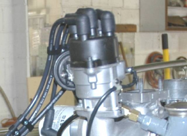
The electronic distributor that suits the Jowett installation is a
Toyodenso from a 1982 Honda Civic. For an optimum installation, some changes to
the distributor body and drive shaft are recommended. More detail on this later
on.
Electronic Ignition – Description
 Above:
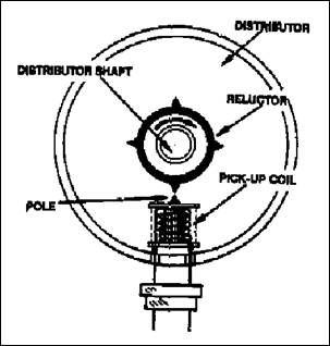
In electronic ignition, a pulse is generated each time a tooth of the reluctor
passes the pole of the pick-up coil.
Above:
In electronic ignition, a pulse is generated each time a tooth of the reluctor
passes the pole of the pick-up coil.
The distributor used with electronic ignition performs the same
functions as those performed by a contact breaker type distributor, but an
electronic sensor is used instead of 'make and break' points. The sensor
determines when a spark should occur and a transistor, used as a switching
device, breaks the ignition coil primary circuit to produce a high voltage for
the spark. The rotor and distributor cap perform the normal function of
distributing the voltage to the sparking plugs.
The sensor consists of a reluctor, or signal rotor on the
distributor shaft, and a pick-up coil on the distributor housing, which form a
pulse generator. As the distributor shaft rotates, teeth on the reluctor pass
the pole of the pick-up coil and a small electric pulse is generated each time
this occurs. The reluctor has one tooth for each cylinder of the engine.
The ignition system has an electronic control module, also called an
igniter, to which the pulse signal is directed. Whenever a pulse is received, a
transistor in the control module opens the primary circuit to produce a spark
from the ignition coil. The transistor is merely an electronic switch which
performs the same function as the 'make and break' points in a contact breaker
ignition system.
The pulse generator which has been briefly described, is known as an
inductive pulse generator.
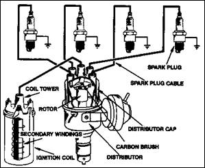
Above: The secondary
circuit produces a high voltage and distributes it to the sparking plugs.
The Secondary Circuit
The secondary circuit of the distributor is responsible for
distributing the high voltage produced in the ignition coil to the sparking
plugs. The distributor is fitted with a moulded plastic cap which carries the
high tension cables. The cable in the centre post in the cap is connected to
the ignition coil and this carries high voltage from the coil to the
distributor. The sparking plug cables are located around the cap in engine
firing order and connected to the sparking plugs.
The distributor cap is secured to the distributor housing with two
Allen head setscrews, and the cap is sealed against water ingress by a rubber
gasket.
The rotor arm, located inside the distributor on top of the
distributor drive shaft, rotates with the shaft to distribute high voltage to
each sparking plug cable post in turn. The high voltage produces a spark across
the electrodes of the sparking plug to ignite the air-fuel mixture in the
cylinder.
Engine Firing Order
The Jowett engine employs the firing order of 1-4-2-3. This firing
order is marked clearly on the motor car's chassis identification plate.
The distributor cap has an embossed '1' adjacent to the sparking
plug cable post for that cylinder. The rotor arm, when viewed from above,
rotates anti-clockwise and the other cables are connected in the continuing
firing order 4, 2, 3 from number one cable post.
Installing The Electronic Distributor
The Toyodenso TD-03D is, very likely, the most desirable distributor
specification. That model was not readily available, and a TD-03E was obtained,
therefore the advance characteristics were set to match the last Jowett Cars
Limited specification. At the same time the distributor was mechanically
overhauled.
The Toyodenso and Lucas distributor bodies are virtually identical.
However, the Toyodenso features a longer shank for mounting into the engine. As
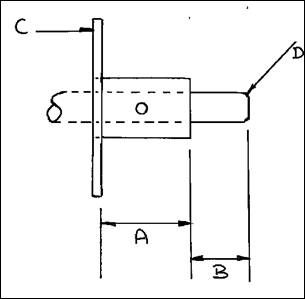
a result, the drive shaft is correspondingly longer. The sketch at right,
illustrates the dimensions that the Toyodenso unit can be modified to, so that
it can be installed directly into the Jowett engine.
The relevant dimensions (sketch not to scale) are as follows:
'A' 1.500"
(Length of distributor spigot)
'B' 1.00"
Length of shaft beyond spigot face)
'D' 0.125"
Radius
'C' Reference point, adjuster plate –
dimensions
taken from RH face
Item 'C' is the mounting plate, also known as the adjustment plate,
that is secured to the base of the distributor housing. A new plate was made
from 4 mm thick aluminium plate. Care needs to be taken when making the
adjustment plate, because its final shape has to be determined from whether the
engine's front timing cover has the adjuster plate lug aligned at right angles
to the engine centre line (earlier models with DKY type distributor), or, if
the cover has two lugs aligned parallel with the engine centreline (Series III
front timing cover for Lucas DM-2 type distributor). Start with a larger than required
flat plate, and mark out the hole for the distributor mounting spigot to pass
through. Next, mark out the hole for securing the adjuster plate to the
distributor housing. This hole is for a brass 5 mm diameter by 10 mm
countersunk head setscrew. With the adjuster plate attached to the base of the
distributor housing, mark out the curved slot in the plate, so that, when
installed, the distributor assembly will be free to pivot on the timing cover
flange. Make the slot of generous length, to provide plenty of adjustment when
setting the ignition timing.
At this stage it is a good idea to mount the distributor assembly to
check that, particularly on the Jupiter engine, there is generous clearance at
the water pump. The best position is with the vacuum unit facing towards the
rear. This positioning provides maximum swing of the distributor for ignition
timing adjustment purposes.
Once the adjustment slot position has been determined, and the slot
has been cut, the adjuster plate can be 'slimmed' to match the timing cover
flange, but still covers the two breather holes in the sides of the housing.
Timing The Electronic Distributor
Depending on whether the original distributor was a DKY type or a
DM-2 type, there will be a differing drive slot orientation at the oil pump
shaft. Essentially, this does not matter – a distributor with an unpinned drive
dog can be set in any position. It is important that the distributor shaft is
set so that the metal end of the rotor arm is pointing to number one cylinder
sparking plug cable post in the cap. This aligns the reluctor with the pick-up
pole. There is a thrust washer between the drive dog and the distributor
mounting spigot The Lucas drive dog should be a snug fit on the Toyodenso
shaft, make sure that it is just loose enough to let the drive shaft turn in it
when the rotor is turned. If it is very loose, find a better fitting drive dog,
or use a piece of Blue-tack to semi-glue it to the shaft. Set the engine to top
dead centre (TDC) on the firing stroke at number one cylinder. With the Jowett
drive shaft, Part Number 50882 attached to the dog by its circlip, carefully
install the assembly into the engine. Hold the housing in the position that was
determined to provide clearance at the water pump body. Gently rotate the rotor
arm, until the tongue of the drive shaft engages in the oil pump shaft
coupling. The distributor should drop into its home position. Carefully rotate
the rotor arm so that the distributor shaft slips in the drive dog, until the
metal end of the rotor arm is pointing at the cable post for number one
sparking plug.
Without disturbing the rotor arm or the drive dog on its shaft, lift
the distributor out of the engine, place the dog in a drill bench vee block and
drill through the dog and shaft with a 1/8" diameter drill. There should
be 0.002" to 0.005" end float at the distributor drive shaft after
the dog is pinned. Clean away any residual swarf and drive in a spring tension
pin, Part Number 50615 from club stock, making sure that the split side is
facing the direction of rotation.
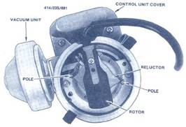
Above is shown a typical electronic distributor with the cap
removed. It is neither the Toyodenso TD-03D nor the TD-03E, but it ably
illustrates the main components of the electronic distributor.
Before tightening the adjuster plate securing screw, apply a drop of
Loctite Studloc 262 under the countersunk head of the setscrew. Fully tighten
the screw. Do not allow the Loctite liquid to migrate along the thread,
otherwise setscrew removal in future will be extremely difficult.
The distributor can then be installed, with the rotor arm pointing
directly at number one cable post; with the engine set to TDC firing on number
one cylinder. Lock the adjuster plate in this position and rotate the
crankshaft through two revolutions and recheck the timing again. If it is not quite
correct, slacken off the adjuster plate nut and rotate the distributor housing
until the reluctor points align with the poles in the body. Tighten the adjuster
plate nut.
The engine should start and run at this setting.
NOTE: It is important to be aware that, due to the electronic
ignition system’s characteristics, the use of a ‘cheap’ ignition timing light ,
there will be seen to be an advance of 44° to 48° degrees of
advance as the engine revs rise. There is no cause for alarm when such advance
is observed.
It is best to set the static timing and then adjust under road test
conditions as stated in the Jowett Maintenance Manual.
Ignition Control Module (Igniter)
The module connector has five pins, arranged as shown below:


Note: This view is from the cable side of connector (looking at male
portion of module). The cables are identified as follows:
Top
Row – Left Green, to distributor (green)
Top
Row – Centre Black/white double bands, to earth
Top
Row – Right Blue/brown bands, to coil, negative (–)
Lower
Row – Left Blue, to distributor (blue)
Lower
Row – Right Black/white, power supply to ignition system 12 volt
The ignition control module should be mounted
on a bracket, away from engine vibration and in a relatively cool area. On the
Jupiter, it was found that an angle bracket suspended from the RHS horn mounting
was ideal. Keep the cable away from the engine cooling fan.
Igniter Notes
Ignition modules (also called igniters) are sensitive
electronic components and require careful location, away from heat and moisture
to ensure optimum performance in the areas of Dwell Control, Primary Current
Control and Primary Induced Voltage Clamping. Efficient primary current / dwell
control is very important in order to get the most energy from the ignition
coil.
Insufficient current I dwell leads to Iow
ignition coil output resulting in difficult starting, breaking down under load
and misfiring at high rpm.
Excessive current dwell leads to
overheating of ignition coil and the ignition module, causing premature module
failure and possible damage to other vehicle components.
Excessive primary induced voltage
leads to possible damage to coil and modules as well as other components
connected to coil negative such as tachometers, security systems and LPG
safety switches and closed loop controllers.
Written by Tony George.
Compiled by Mike Allfrey.
January, 2006.