Introduction
Because the ‘Competition Tuning Notes – For The Jowett
Javelin’ were published in 1952, many more modifications were implemented after
that date which make some of the information irrelevant or vague. Also, many of
the parts mentioned were superseded or are no longer available, however in some
cases parts from other vehicles may be modified to suit. Produced here are the ‘Notes’
and (in italic type) Neil Moore's comments and information.
These instructions apply to the Javelin car and
are intended as a guide to tuning for maximum performance.
It is extremely important that these are read in conjunction
with the Maintenance Manual for the Javelin, which describes in detail the
work involved in stripping and assembling the units concerned. In addition, it
is important that the standards of workmanship and cleanliness are of the
highest order if success. is to be assured.
1. ENGINE
It is important that the Cylinder Heads are polished and
subsequently corrected for capacity in the following manner:
a) Induction and Exhaust Valve Ports – In addition to generally
polishing out the ports, some benefit may be obtained from attention to the
following:
Exhaust Ports – On Cylinder Heads
fitted to early cars, the radius under the lower side of the Exhaust Valve
Seating may be considerably increased. Metal has been removed here on later
castings, increasing the cross section area at the throat of the Port (Fig. 1).
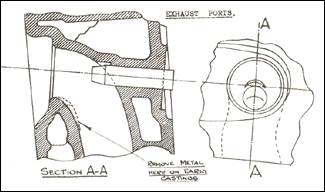
Figure 1. Re-profiling exhaust ports.
b) Inlet Ports – As with Exhaust Ports, early castings have
more metal than is desirable under the Valve Seating. On later castings, metal
has been left on the opposite wall, with improved results. This cannot be done
on the early' castings, but the rough edge may be faired off to reduce the
buffer effect under the shoulder (Fig. 2).
a) NOTE: This porting and polishing procedure applies to PA and PB (Pre 1950) and PC (1950-51). The introduction
of the PD engine (1952) brought a modification to the cylinder
head casting with a vertical web running under the sloping part of the combustion
chamber, giving extra strength when the head has been planed to correct
capacities after porting and polishing. This web is visible through the lower
water passage in the heads.
In the PE Series III (1953) engines
this whole procedure was carried out by the
factory to these instructions.
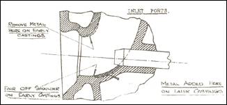
Figure 2. Re-profiling inlet ports
c) Combustion Chamber – All sharp edges should be removed. .The undercuts round each
valve should be blended off to ensure a smooth gas flow and to assist
turbulence (Fig. 3).
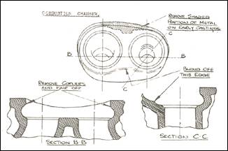
Figure 3. Re-profiling combustion
chambers.
d) Alignment of ports with manifolds. This is particularly important
and can be checked by blueing the flange faces and then bolting up with paper between;
by observing the pattern on each side of the paper, the points where metal is to
be removed to make the ports coincide can be observed.
e) Valves – The Valves and Seats must be in first-class
condition, with no signs of pitting or excessive narrowness. A seat width of
3/32” should be maintained for the Exhaust Valve and 1/16” for the Inlet Valve.
It is important that the turbulence angle is maintained on the Valve Seats, as
shown in Fig 4.
e) NOTE: Early Vauxhall Exhaust Valves of the same head diameter
but of more robust dimensions may be used if the ends of the stems are
shortened to approximately 1/16” above the collet
groove and care taken that adequate clearance is maintained at the top of the
guide in relation to the valve head.
It is recommended that valve seats requiring building up or
cracks needing repair be done by welding –- preferably
by the ‘Eutectic’ process, as this minimises distortion and the resultant weld
deposit can be machined easily.
f) Valve Springs – If it is desired to lift the Valve Bounce point of the Engine above
5,500 R.P.M. stronger Outer Springs should be fitted (our Part No. 52964).
f) NOTE: Part No. 52964 is still
available from L. J. Golding, Auckland.
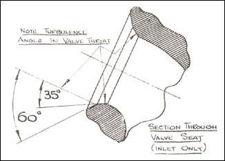
Figure 4. Section through valve seat.
g) Cylinder Head Capacity – After the above work has been completed the capacity of the Combustion
Chamber should be checked as follows:
Remove the Cylinder Head and lay flat on a bench with the
Combustion Chambers face up.
Insert a set of spare Spark Plugs.
Fill the Combustion Chamber with fluid, flush to the face.
This capacity should be between 40 and 41 cc. (Fig. 5).
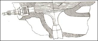
Figure 5. Checking combustion chamber
capacity.
h) Compression Ratio – With the above Cylinder Head
Capacity of 40 to 41 c.c. and a standard Gasket which has a Combustion Space
Capacity of 7½ cc, compressed, the following Compression Ratios may be obtained
by the use of the Pistons quoted:
Piston Part No. 50656 gives 7.2 to
1;
Piston Part No. 53228 gives 7.6 to 1;
Piston Part No. 53227, 8.0 to 1.
(The last two are Higher Compression Ratios)
It is recommended that the higher Compression Ratios should
not be used unless fuel of at least 80 Octane rating, or 25 per cent Benzole
mixture is available.
As a final check the Compression Ratio on the Engine can be
checked as follows:
With the Head in position on the Engine and the Pistons at TDC:
fill with liquid to the level of the Spark Plug Facing, rocking the Engine to make
sure that all air is ejected. The relative volumes should be:
7.2 to 1 = 58 c.c.
7.6 to I = 56 c.c.
8.0 to 1 = 53 c.c.
Note: an error of plus or minus 2 per cent is allowable in the
above volumes.
Any corrections to the capacity can be made by machining the
Cylinder Head Gasket Facing 0.011” (0.2794 mm) removed here reduces the
capacity by 1 c.c.
h) NOTE: Piston supply in New Zealand at present is nil. However
the following pistons can be used – 75 mm and 77
mm Volkswagen pistons, giving approx. 8.8-9.0 to I; 74.9 mm Vanguard
Six and Triumph 2000, giving 8.8-9.0 to 1; 74.3 mm Vauxhall Viva, giving
8.4 to 1. Triumph 1300 are also apparently suitable.
However, these all require modification. and machining to some
degree and it is suggested that advice from someone who has fitted same be solicited
before undertaking this job. Negotiations are at present being made to ensure a
future supply of Javelin pistons.
Australian Note: Pistons to Jupiter specification are
manufactured in Australia. Flat top pistons can be ordered (January 2007).
Copper/asbestos/Steel Cylinder Head Gaskets are available
(Golding), which are 0.010” thinner than copper/asbestos/copper gaskets but
have a slightly larger combustion space capacity which can accommodate larger
pistons.
Petrol in U.K. when the original Notes were written was
"pool" of 70 octane rating.
i) Bearings – Engines up to No. E0/PB/8902 were fitted with White Metal
Connecting Rod and Main Bearings, and an un-hardened Crankshaft. It is advisable
to replace this assembly by an induction hardened Shaft to our Part No. 50647,
which will necessitate the use of Copper Lead Bearings except for the Rear Main
Bearings which remain in White Metal, the Part Numbers of these are Connecting
Rod Assembly – J54444, Main (Front and Centre) Bearings – 52573, Rear Main
Bearings – 50646.(standard sizes).
It is vital when refitting
Bearings that absolute cleanliness is assured and rag should in no circumstances
be used to wipe components: they should be washed in clean petrol and blown off
by air. Great attention should also be paid to the sealing of the Crankcase
Balance Pipe Rubber Ring as detailed on Page 35 of the Maintenance Manual.
i) NOTE: Numerous Bearing changes in numbers and minor details
took place due to JCL chasing the bogey of bearing failure and broken crankshafts.
The main cause showed itself to be starving of the main bearings. especially
the Centre Main Bearing, and over supply of oil to the Big End Bearings. The partial
answer to this problem was enlarging of oil-ways
as in the Series III engine, and the fitting of an oil cooler which gave a
fairly satisfactory life if the Series III grinding sizes were adhered to for
crankshaft. ‘Vandervell’ make Main Bearings for these specifications in copper-lead
(Part No. 1959) with a White-metal Rear Main (Part No. 1960).
Particular attention must be made to retaining 0.100” radius fillets
on regrinding crankshafts. Under no circumstances should White-metal Big End
Shells or White-metal Front and Centre Main Bearings be used.
Perkins ‘Alu-tin’ bearings can be used in Mains providing
shaft tolerance is revised to 2.2500” - 2.2498” and
the groove kept to a minimum (an article on this subject is being prepared).
Alu-tin Bearings for Big End Shells from Humber 90 and Minx (Repco Part No. 4K2911 AL) can be used with shaft tolerance 1.9998”
- 2.000”. These are slightly narrower than Jowett original, but are satisfactory.
For more information about bearings, refer to PART V –
CRANKSHAFT BEARINGS.
Disregard the Jowett Part Numbers quoted in the original text!
Early Crankshafts, i.e., Square Web solid and with 15/16” hole through Big
Ends, should be crack tested before replacing. For high performance, an Oval
Web Shaft should be fitted. (Approx. 30 new ones
are available from Goldings!) The Oval Web Crankshaft was not apparently fitted
until after the factory stopped producing cars early in 1954, but
as the Flat Crankshaft broke with monotonous regularity most have been
replaced. After 1958 the Oval Web Crankshafts were Nitrided – the
date of manufacture being stamped on the Front Web, e.g..3 over 62 being
March 1962.
j) Clutch
– It is desirable to replace the Clutch Friction Disc with one of a woven type
having a greater coefficient of friction, this is available under our Part No.
52420/A.
j) NOTE: This Clutch Plate 52420/A is
the deluxe type available from most retailers. The Pressure Plate normal for
Javelin is Borg and Beck B2 with Blue Springs – however a stronger
Pressure Plate with White Springs can be obtained from Motor Traders Ltd. The
reconditioned Pressure Plate Assemblies from some suppliers are not recommended
as the balancing is very suspect.
It is advisable to have the whole Crankshaft, Flywheel and
Pressure Plate Assembly balanced as a unit by a reputable
balancing firm,
(Mr Ted Thomson of Kumeu, Auckland, is recommended)
k) Carburettors – Special 30 VM. Carburettors with the following settings:
27 mm Choke; 110 Main Jet; 50
Compensating; 2.2 Vent over Capacity; 45 Slow Running; 120 Progression; 1.5 mm
Needle Seating (1 mm Washer) should be fitted in place of the Standard VM. 4 or
5. These Carburettors are interchangeable and carry our Part- numbers LH –
1.53732; RH – 1.53733.
The Throttle Spindle operation is in the reverse direction,
and the Throttle Cable must consequently be rearranged. A suggested method is
to fit a Cable approximately 9”.(25 cm) longer than
standard, securing the Inner Cable to the Bracket on the left hand Tappet
Cover, and the Outer Cable to the Throttle Rod. The Throttle Return Spring
should be connected to the Clip to which the original Outer Cable was secured
on the right hand Tappet Cover.
k) NOTE: This 30 VM Carburettor is available from Joseph Lucas,
but 'the jets will have to be altered and pairs will not be available –- only
one side. This will mean that the controls on one side will be on the outside;
however controls from an old carburettor could be substituted. The main point
to watch is the position of the hole for the Advance/Retard Fitting to the Distributor.
Some carburettors use this fitting with a hole to the underside of the
butterfly for a vacuum brake booster unit and if this is fitted to a
Distributor will give full Advance on starting up. The hole should be on or
slightly above the butterfly.
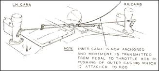
Figure 6. Throttle cable arrangement
l) Water Pump – On all Engines prior to PA.5857 the Water Pump should be modified
to increase its capacity to 7 gallons/min. at 1,500 R.P.M. On Engines
subsequent to the above number the modification was incorporated. The modification
consists of a modified Cover and the addition of a Shroud Assembly to the
Impellor, as shown in Fig. 6.
In addition to the above the Thermostat should have the 2
Bleed Holes enlarged to 3/16” diameter if prior to the above number.
l) NOTE: ‘Waxstat’ failsafe Thermostats are now available for the
Javelin and are a more positive type of thermostat. As the Pump Bypass is
through the 3/16” holes, these should be drilled in the valve plate.
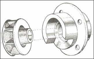
Figure 7. Left: Impellor shroud;
Right: Later cover.
m) Oil Pump – It is recommended that an Oil Pump of
increased capacity be fitted to our Part No. AS.52403. Engines built subsequent
to PA 800 have this modification incorporated.
m) NOTE: The Oil Pump mentioned had a 3/8” OD 5/16” ID discharge
pipe to block and fixed adjustment. From E1/PC/18985 a tailpipe was fitted to
the Bottom Cover Relief Valve hole to direct discharging oil under the surface
and stop aeration. From E2/PD/21937 and E2/SA/882 (Jupiter) September 1952 an
increase in the Discharge Pipe to 7/16” ID and Internal Galleries of the Block
was made. From E2/PE/23122 and E2/SC/945 (Jupiter) December 1952 a deeper pump
was used with the same gears and a new Base Plate with Relief Valve returning internally
to suction side of pump. The Relief Valve was fully adjustable and set at 65 - 70
psi. Refer to Part IX – OIL PUMP.
NOTE: The oil pressure was raised to allow for extra
resistance of oil cooler pipes to maintain adequate flow.
n) Oil Cooler – It is recommended that the Rear Timing Case Cover Part No. 50690
and early type Oil Filter Assembly should be replaced by the latest type
Assembly. Engines built subsequent to El/PC/16603 incorporate this latest type
of new Rear Timing Case Cover to our Part No. 53030 and Tecalemit Oil Filter
Assembly.
The above allows an Oil Cooler,
Part No. J54532 to be fitted as shown by use of two Flexible Pipes to Part No.
J54519.
n) NOTE: Disregard Oil Cooler Number –- not available. A VW Cooler
can be used modified as per article by G. Fisk in ‘Flat Four’ 1966.
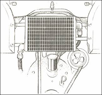
Figure 8. Oil cooler installation from
front.
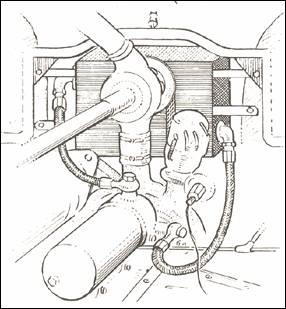
Figure 9. Oil cooler installation from
rear.
o) Fan – The Fan Blades should be stiffened by the addition
of extra welding along the base of the Blade where it abuts on to the Centre
Spider. This will necessitate re-balancing the Fan Assembly which can be done
by mounting it on a suitable arbour and rolling on knife edges, metal being removed
from the tips of the Blades in order to restore static balance.
o) NOTE: An 'Electric Thermostatically Operated Fan could be
fitted with advantage behind the Radiator. (A future article on this is
promised.-Ed.)
p) Ignition Setting – The recommended setting is with the
points breaking at approximately ¼” (6.5 mm) ATDC (measured on the Flywheel
Rim). This setting will cause the Engine to ‘pink’ on 1/3 to ½ Throttle at
20-30 M.P.H. (32-48 K.P.H.) when suction advance is operating. The ‘pink’
should disappear completely on Full Throttle.
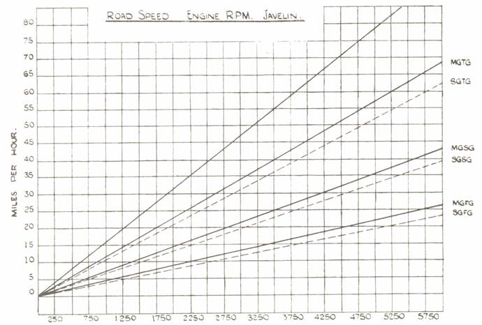
2. GEARBOX
Special constant mesh Gears, providing a higher ratio in
the Intermediate Gears, are available, and we are, therefore, including a chart
showing the road characteristics with the various ratios (Fig. 4). These carry
our Part Numbers as follows:
Stem Gear - 52733 (19 teeth);
Layshaft (Cluster gear) – 52734 (33 teeth).
Note: Cars fitted with gearboxes numbered J1 upwards, on the
gearbox top, Incorporate these ratios.
NOTE: It is recommended that a large centre main
shaft thrust washer be fitted. They were fitted to late model gearboxes.
3. TRANSMISSION
Propellor Shaft Universal Joint (50916). These Joints, particularly at the front should be carefully examined
on all cars which have run more than 6,000 miles (9,000 km) and it any rubbers
show signs of deterioration the Joint should be replaced.
4. BRAKES
It is
recommended that high duty Linings be fitted for high speed competition work,
and we would recommend: Mintex M.14 or 15; Ferodo M.R. 41
Care should be taken to specify whether the car has the
early Hydraulic Front, Mechanical Rear operated system or the Full Hydraulic,
when ordering.
5. SUSPENSION
Rear
Shock Absorber Upper Pin – A modification to
stiffen up the Rear Shock Absorber Upper Pin was introduced at Car No. 17672.
Check that this has been carried out and if not modify the Mounting of the. Pin
in accordance with Fig. 7.
Shock Absorbers – A 25
per cent stronger all round setting is recommended for most types of
Competition work. As an alteration in the setting involves complete dismantling
of the Shock Absorbers, replacement by the stronger type is advised: These
carry our Part numbers Front 54385 (fitted as standard from Engine No. 16500),
Rear 54675 (Competition).
NOTE:
From E2/PD/2188 and Jupiter E2/SA/865 the New Metalastic Rubberised Suspension
was fitted. This is a superior suspension in all respects to the earlier type
for competition work. The 25 per cent stronger
type early Shock Absorbers are the only type available now.
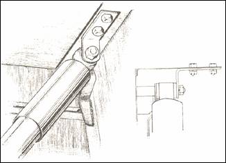
Figure 10. Arrangement of rear shock
absorber mount.
6. GENERAL EQUIPMENT
Batteries – It will be
found advisable to protect these at the front and base with a sheet metal case
for high speed motoring over loose surfaces.
7. NORMAL SERVICE
In addition to the special work described above, it is very
necessary that the normal servicing of the car as detailed In the Instruction
book and the Maintenance Manual, is carried out.
8. SPARES
The special items previously mentioned are summarized herewith for
easier reference:
Part Description Part
Nos.
Stiffer Outer Valve Spring 52964
7.6:1 Compression Ratio Piston 53228
8.0:1 Compression Ratio Piston 53227
Induction Hardened Crankshaft 50647
Copper-Lead Connecting Rod Bearing Assy J54444
Copper-Lead Main Bearings, Fr & Ctr 52573
White-metal Rear Main Bearing 50646
Higher Coefficient Clutch
Friction Disc 52426/A
30 VM. Carburettor-LH 1.53732
30 VM Carburettor – RHS 1.53733
New Type Water Pump Cover 52710
New type Water Pump Impellor 1.54414
Latest type Thermostat 50768
Increased Capacity Oil Pump AS. 52403
Latest type Rear Timing Case
Cover 53030
Tecalemit Oil Filter Assembly 53422
Oil Cooler J54532
Flexible Oil Cooler Pipe – 2 off J54519
Higher Ratio Stem Gear 52733
Higher Ratio Layshaft 52734
25 % Stiffer Absorbers – Front 54385
25 % Stiffer Shock Absorber – Rear 50467S
9. JAVELIN ROAD CHARACTERISTICS
Back Axle Ratio – 4.875:1
Gear Ratios – Modified Gearbox
First Speed 1:17.4
Second Speed 1:10.6
Third Speed 1:6.70
Top Speed 1:4875
Gear Ratios – Standard Gearbox
First Speed 1:19.0
Second Speed 1:111.6
Third Speed 1:7.34
Top Speed 1:4875
Rolling Radius of Tyre 12.7in - Tyre Size 5.25 - 16.
Valve Spring Surge occurs at 5,500 revs. per min. with
Standard Valve Springs.