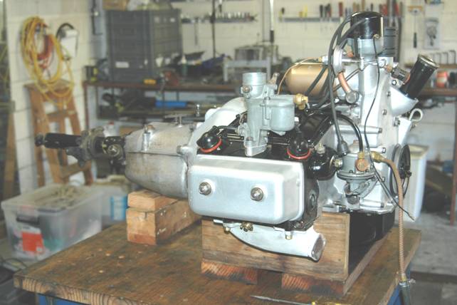
Purpose
For practical
purposes the Javelin and Jupiter engines will be termed as the Jowett engine.
This detailed procedure has been written to assist those faced with
the task of assembling the Jowett engine, but also for those who have little
experience with this engine, or those who find that the Maintenance Manual
assumes too much knowledge, or those who would benefit by a memory jogger. It
is also designed to assist where the engine has ended up with parts that are different
from the original assembly.
It maps out the steps and practices for not only achieving a smooth
and efficient assembly, but also avoiding common and uncommon mistakes, and maximising
the likelihood of a successful, reliable, long term operating performance and
life, particularly with regard to avoiding future oil leaks.
This procedure is based on direct observation, questioning and
participation in the assembly of my engine by Mike Allfrey. These Technical
Notes have been edited and approved by Mike.
Read this assembly procedure in conjunction with the technical
recommendations made in ‘An Introduction to Overhauling the Jowett Javelin/Jupiter
Engine’ by Mike Allfrey, 20/3/2002. Particular attention should be paid to
improving the oil transfer system, as this is the heart of an engine. All
technical modifications were made to my engine, as recommended, and all parts
were overhauled. This procedure therefore assumes that all parts being fitted
are not worn in any way and offers no advice if they are.
Reference Material
These notes have been written assuming that the final document will
be placed on Compact Disc. Within the text, reference will be made to other
books in the Technical Notes series, which will also be placed on the same
disc. A number of topics have been covered in detail and there is no point in
repeating techniques again.
These notes should be used in conjunction with the following series:
- Technical Notes – Introduction to Jowett Engine Overhaul
- Technical Notes - Crankcase
- Technical Notes – Crankcase Studs
- Technical Notes – Engine Bearings
- Technical Notes – Oil Pump
- Technical Notes – Cylinder Liner Installation
- Technical Notes – Cylinder Head Gasket
- Technical Notes – Rear Timing Cover Gasket
- Technical Notes – Engine Cooling System
- Technical Notes – Gearbox Oil Leaks
General Requirements
- The terms ‘left’ and ‘right’ apply as viewed from the driver’s
seat and looking forward.
- Threaded studs are screwed into their threads to a torque value
that is 20 per cent of that applied to the nut on final assembly.
- A clean working environment free of dirt and clean parts that
are free of rust, oil and dirt are essential, as are a copious supply of
clean rags. All re-used hardware should have been wire-brushed, protective
coating applied (Inox, WD-40 or such) and stored in labelled, re-sealable
plastic bags that are stored in logical groupings, ready for easy location
as required.
- The term ‘wash’ means thorough scrubbing in heavy duty
degreasing fluid, rinse with fresh water and blow dry with clean
compressed air. It is assumed that all parts have been previously cleaned
and stored in a sealed condition. Reference to cleaning and washing here
is in addition to this.
- Check that the flywheel is a snug fit on the crankshaft spigot.
Any looseness will result in severe vibration and can cause flywheel
fixing bolts to fracture.
- Some crankshaft re-grinders ‘clean-up’ the oil seal contact
area at the back of the crankshaft. This action ruins a good crankshaft.
This situation is not a complete loss, the flywheel can be set up in a
lathe and be machined at the spigot recess to enlarge it. A ring can be
machined and shrunk into the recess to form a new spigot diameter.
- The front crankshaft pulley, crankshaft, flywheel and clutch
should be dynamically balanced as a group prior to any assembly taking
place. The clutch pressure plate and flywheel should be stamped with ‘X’
adjacent to one of the clutch locating dowels, for assembly purposes,
- Balance weights must not be welded to the outside of the clutch
pressure plate assembly, lightening drilling method should be used. Welded
weights can clash seriously with the inside of the flywheel/clutch
housing.
- Ideally, the front timing cover, crankcase set and the
flywheel/clutch cover should be matched sets. The crankcase set numbers
should also match. The easy way to establish authentic components is to
dry-assemble and check that the sump gasket surfaces of all four
components are absolutely flush.
- Carburettor balance pipe seal test rig
- All references to tightening torque values are given as lb.ft.
(pounds. feet)
Greases, oils, sealants, etc. were:
·
Valvoline Heavy Duty Degreasing Fluid
·
Nulon Xtreme 90 Teflon assembly lubricant for
all working surfaces (e.g. crankshaft journals and other slide fit joints)
·
Castrol PH Zinc Oxide (white) grease, for clutch
and gearbox splines
·
Penrite HPR-30 Engine Oil
·
Penrite SAE 70 – 80 Manual Transmission Oil
(gearbox)
·
Penrite Copper Eze, for studs and bolts that
could freeze due to corrosion
·
Loctite 515 Mastergasket sealant – used at engine
oil sump, front and rear timing covers, tappet chests, water elbows, petrol
pump flange and carburettor gaskets
·
Loctite 518 Mastergasket sealant – used at all
metal to metal joints at oil-wet areas
·
Loctite Blue RTV (34248) sealant – used at internal
balance pipe joints, breather pipe where it enters crankcase, oil filler tube
to timing cover, inside carburettor spacer and cylinder head cover, front cover
of water pump, water pump gland seals
·
NOTE: When applying a ‘smear’ of Loctite sealant,
it means just that – a very thin application of the sealant.. The application
should be as even as possible. A feature of Loctite anaerobic sealants is that
they only cure in the absence of air. They also ‘grow’ during curing.
·
Loctite Studloc 272 – used for flywheel bolts,
front pulley bolt, connecting rod bolts
·
Loctite 680 Adhesive – used for securing loose
push rod seats in cam followers
·
Loctite 569 Pipe Thread Sealant – used for
breather pipe joint fittings
·
Loctite JS1 Exhaust Joint Putty
·
Loctite 290 Wick-in Sealant – used for gearbox
joints, layshaft spigot
·
Loctite 471 cleaning and accelerator fluid
·
Methylated spirits – used for final cleaning of
surfaces treated with Loctite products (slows curing rate to permit assembly
procedures)
·
Thread cutting compound – for steel and aluminium
·
Brass and aluminium drifts of suitable size
·
Aluminium covers for vice jaws to protect delicate
parts
·
Correct size BSF spanners and sockets, and a
good quality torque wrench with ½” square drive.
Engine components are
traditionally painted as follows:
·
Black paint is used for cylinder heads, tappet
chest covers, water pump extension tube assembly, dynamo support bracket, fan
belt tensioner arm assembly, front crankshaft pulley, engine mounting brackets,
coolant water inlets, engine oil sump, flywheel cover, starter motor and dynamo
·
Red paint is used for cooling fan assembly
(Javelin), Top Dead Centre (cylinders 3 & 4) marking on flywheel
·
White paint is used for cooling fan (Jupiter),
Top Dead Centre (cylinders 1 & 2) marking on flywheel
·
Yellow paint is used for the 12 degree Before
Top Dead Centre marking on flywheel
Prepare Crankcase
1. Clean up all
stud threads using a good quality die nut with cutting compound.
Clean up
threads with bottoming taps in all castings.
If
there is any doubt about the structural integrity of the crankcase at stud
threads, it would be better to find out now, rather than when components are
being assembled. It is a good idea to trial fit and torque the cylinder heads
if there is any doubt. If a stud pulls out at this time, it is easily accessed
for fitting of a Recoil thread insert.
Check
that there are no hollows in the cylinder head gasket surfaces.
2. Thoroughly
wash and dry the crankcase set.
NOTE:
Check all gasket surfaces are free of burrs, deep scratches and deformation
around studs. Make sure that all gasket surfaces are absolutely flat.
Setting Cylinder Liner Protrusion
3. Lightly
oil the cylinder liner skirts to facilitate easy insertion and withdrawal with
respect to the crankcase set.
4. Working
on one half of the crankcase at a time, mount it on a wooden surface, with the
cylinder head gasket surface uppermost.
5. Carefully
check the cylinder liners against each other for skirt length and water jacket
length. Cylinder liners may not be of a matched set of four. Check that the
crankshaft clearance notches are equal in size. A smaller notch, especially in
conjunction with extra machining having taken place, may cause interference between
crank throw or connecting rod bolt head and the liner skirts.
6. Fit
the liners, less any shims and spacers, into the crankcase half. Line up the
head gasket support ledges.
7. Working
on one cylinder liner at a time, mount a good quality straight edge across the
cylinder head gasket surface and over one of the liners. At four points,
measure, with good quality feeler gauges, the distance from the cylinder liner
lip and the head gasket surface. Calculate the average dimension for the four
measuring points and add 0.006” to 0.008” to calculate the spacer and shim pack
required to provide the correct cylinder liner protrusion.
8. Fit
each cylinder liner, with the calculated shim packs and verify correct cylinder
liner protrusion, using the straight edge across the cylinder liner lip.
9. Number
each cylinder liner with white oil based marker pen according to the cylinder
numbering sequence on the chassis serial number plate.
Assemble The Crankcase
10. Install
all studs into crankcase set.
NOTE:
Those studs that screw into threaded holes open to fluids should be installed
with Loctite 518 applied to the threads. Those studs that screw into blind
holes should have threads coated with Penrite Copper Eze.
11. Mount
the RHS crankcase half on the bench. It is a good idea to use an old cylinder
head gasket to drill 11 mm diameter holes in the bench top for the head studs
to pass through. The crankcase half should then sit firmly on the cylinder head
gasket surface.
12. If
separate thrust bearing slippers are being used, they should be installed now.
The securing screws should have a small droplet of Loctite 272 applied under
the countersunk head only – not at the thread.
13. Fit
main bearing shells into place over locating dowels. Do this on both halves.
14. Apply
a smear of Nulon L90 Xtreme assembly lubricant to the main bearing shells.
Place crankshaft into crankcase half that is located on work bench.
NOTE:
If necessary, install a new spigot bush in the rear of the crankshaft. Soak
bush in oil overnight.
15. Push
one internal balance pipe seal onto the pipe. Apply a smear of Loctite Blue RTV
to the pipe and push fully home onto its seat in the RHS crankcase half. Push
second seal so that it just sits on end of internal balance pipe, so that the
seal ring will slide down as the upper half of the crankcase is pushed down into
its home position. Apply a smear of Loctite Blue RTV sealant.
16. Thoroughly
clean joint faces with methylated spirits. At the upper joint face, where the
five ¼” bolts pass through, apply a smear of Loctite 518 all the way along
upper edge. Do not apply sealant to any other joint faces. NOTE: Application of
Loctite 518 to crankcase joint faces will upset crankshaft main bearing
clearance, causing low oil pressure indication.
17. Install
the crankcase tie bolt nuts, with thread lead facing bolts.
18. Install
the two crankcase tie studs. Fit the lower nuts and plain washers. Support the
two studs with suitable blocks.
19. Position
the LHS crankcase half carefully above the other half, taking particular care
where it will meet the internal balance pipe. In a controlled manner, slide the
LHS crankcase half down onto its mating surface/ Push it fully home. The seal
ring should gently slide into position without being cut.
NOTE:
Use a pencil torch to observe behaviour of the balance pipe seal as upper half
of crankcase is lowered into position.
20. Working
quickly, install all crankcase joining hardware. Apply beads of Loctite 518
under the plain washers of the tie bolts, studs and upper five ¼” bolts (under
washers at heads and nuts – no spring washers here).
21. Wipe
away any sealant that may have squeezed into the camshaft bearing bores.
22. Tighten
the tie bolts and studs evenly and tighten to torque value of 75 lb.ft. Fully
tighten the upper five bolts.
NOTE:
All crankcase joint bolts and studs must have good quality plain washers
installed. These bolts and studs pass through oil wet areas, the application of
Loctite 518 under the plain washers and around the bolt and stud shanks is used
to prevent engine oil migration..
23. Use
Nyloc self locking nuts at the top five bolts.
24. With
a clean rag soaked in methylated spirits, wipe any excess sealant from securing
hardware.
Test Internal Balance Pipe Seals
25. Using
the balance pipe test rig, carry out a vacuum test on the assembled balance
pipe. The test rig is shown in detail in the Javelin/Jupiter Maintenance
Manual.
26. Seal
both ends of the carburettor balance pipe. A foot pump converted at the piston
washer is used to create a vacuum at the crankcase breather pipe.
27. A
vacuum of 18” hg (mercury) should be held for 10 minutes. If there is a rapid
loss of vacuum, this indicates a cut seal – or worse – a pin hole in the
balance pipe somewhere. Kerosene can be pumped into the sealed-off pipe and the
position of the leak determined.
NOTE:
A cut seal may not indicate a leak in the pressure test. This test is primarily
used to find pin holes in the pipe due to abuse or rust corrosion.
Any
leakage found at this stage will have to be rectified before proceeding
further.
Continue Crankcase Assembly
28. Apply
Nulon L90 Extreme assembly lubricant to the working surfaces of the camshaft
and install it into its bearing bores.
29. Lift
the crankcase assembly into a horizontal position. It is a good idea to mount the
assembly on a wooden stand that supports it under the water jackets at each
side.
30. Measure
the cylinder head gasket support and machine it so that it is flush with the
cylinder liner lips (i.e. it protrudes 0.006”).
NOTE:
Consider at the same time, machining a recess in the base of the support to
accept an ‘O’ ring to seal the stud from water migration. This will protect the
support and stud from corrosion. Apply a smear of grease to the bore of the
support housing.
31. With
the cylinder liners absolutely clean and using methylated spirits, wipe the
seats for the liners in the crankcase. Mount the spacers and shims on to each
liner as determined in Step 7. Apply the smallest smear possible to the spacer
that will come into contact with the seat in the crankcase.
NOTE:
If worn cylinder liners are being installed into the crankcase, they should be
individually placed in the crankcase from which they were extracted. Once wear
has taken place, each liner becomes unique due to the thrust of the power
stroke being on the underside on the LH bank, and on the upper side on the RH
bank. This fact is most important!
32. Apply
a smear of clean engine oil in the crankcase liner bores. Do not oil the
cylinder liner skirts and make sure no oil reaches the liner seats.
33. With
the cylinder liners in pairs, and the cylinder head gasket support started on
the centre stud, slide the two liners into place. Make sure that the clamping
ledges are correctly aligned.
34. As
soon as the cylinder liners are installed, clamp them into place using suitable
plain washers and spacers on four head studs per liner. Tighten the nuts
equally.
Installing Piston And Connecting Rod Sets
35. Wash
all parts. Carefully inspect the connecting rods, which should have been crack
tested. Look for surplus identification marks. These are totally unnecessary.
‘Mechanics’ in the past have been known to identify the connecting rods with
their respective cylinders by marking with hacksaw, file or centre punch. Of
these, the centre punch is the least harmful to the connecting rod.
Jowett
Cars Limited, marked each rod and cap with a two-letter code. It is a simple
matter to record the letter codes with their respective cylinders for future
reference.
NOTE:
If the connecting rods have been re-identified with hacksaw or file marks
(notches), these will have to be linished out and the connecting rods re-equalized.
Failure to do this will result in a damaged engine!
NOTE:
Carefully inspect the connecting rod bolts – replace with new bolts if there is
any evidence of ‘necking’, corrosion or abusive damage to the bolt heads.
36. Install
one gudgeon pin circlip into one groove in the piston.
NOTE:
Circlips are manufactured with tapered circlip pliers holes. Install the
circlip with the pliers prongs entering the smaller diameter of the holes. This
will make circlip removal easier in future.
37. Fit
the piston onto the connecting rod by pushing in the gudgeon pin as far as
possible by hand. Complete the installation using a suitable aluminium drift.
Install the second circlip. Make sure that both circlips are fully ‘seated’
within their grooves.
38. Centre
the piston on its pin over the connecting rod and work it to ensure that it is
not too tight at the small end bush.
39. Prior
to installing the piston rings onto the piston. They should be checked for
correct gap dimensions by placing the rings 50 mm in bored cylinder, sitting
squarely. The gap can be measured using good quality feeler gauges. This gap
should be between 0.007” and 0.015”.
40. There
could be two types of oil control rings:
a)
multi-segmented type
b)
plain slotted cast iron ring
41. For
the first type, install first the expander part of the ring set. Then install
the bottom scraper ring, the spacer segment and finally the upper scraper ring.
The joints of each segment should be spaced equally from each other. Apply copious
amounts of clean engine oil while making up the segmented oil control ring.
42. For
the second type, the ring should be oiled with clean engine oil and then
carefully expanded to just fit over the piston diameter. In cold weather
conditions, it is advisable to warm the ring in hot water before installation.
43. The
second and first compression rings should be installed. The gaps of all rings
should be equally spaced around the piston.
44. Soak
the rings in clean oil and fit a good quality piston ring clamp over the rings
and tighten firmly. Make sure that the tightening lugs are oriented so that
they pass between cylinder head studs.
45. Invert
the crankcase assembly on its support stand so that the sump gasket face is
uppermost.
46. Lightly
oil the cylinder liner bores.
47. Install
the big end bearing shell into the connecting rod.
48. Make
sure that the cylinder liners are firmly clamped in the crankcase. In addition,
check that clamping devices do not interfere with the piston installation
process.
49. Make
sure that the piston ring clamp is sitting squarely on the cylinder liner lip.
Hold the clamp assembly firmly against the cylinder liner lip, while the piston
is pushed home into the bore.
50. Apply
a smear of Nulon L90 Xtreme assembly lubricant to the crankpin journals and
pull the connecting rod squarely onto the journal. Install the connecting rod
cap, with identification code s aligned, onto the connecting rod. Wash the connecting
rod bolts with Loctite 471 Primer. Allow to dry thoroughly and apply a drop of
Loctite 272 Studloc at the female threads. Tighten the connecting rod cap bolts
to 35 lb.ft.
NOTE:
Current pistons supplied by the Jowett Car Club of Australia Inc. have solid
skirts. This means that the piston can be installed either war round onto the
connecting rod.
In
the instance where split skirt pistons are being installed, careful note should
be made of the word ‘FRONT’ stamped into the top face of the piston. In a
horizontally opposed engine, the thrust side is opposite on each bank of
cylinders and, great care must be taken during the task of attaching the
connecting rods to the pistons.
51. Repeat
Steps 36 to 49 for the remaining three cylinders.
NOTE:
Check that the crankshaft will rotate after installing each connecting rod. If
there is ‘lock-up’, then it should be investigated at once.
Install Cylinder Heads (Complete)
52. With
the crankshaft set in one position, remove the cylinder liner clamping devices.
53. Thoroughly
clean the cylinder head gasket contact surfaces. Apply a smear of Loctite 515
Mastergasket only to the water jacket surfaces on the crankcase, and around
where the carburettor balance pipe forms a joint, and where the oil feed stud
passes through the gasket.
54. Refer
to Technical Notes – Cylinder Head Gasket for installation procedure.
55. VERY
IMPORTANT: Before installing the cylinder heads, make sure that the coolant
water inlets are installed and fully tightened.
NOTE:
There should be no paint on the elbow faces that contact the gaskets. If paint
is left on the flange, the gasket could ‘walk’ out when the nuts are tightened
down.
56. Modern
cylinder head gaskets feature a small ‘O’ ring that must be installed over the
oil feed stud. The purpose of the ‘O’ ring is to prevent oil, under pressure,
from migrating into the cooling water.
57. Install
coolant drain taps, Tighten without force on tap handle, and using new fibre
washers.
Install Valve Rocker Gear
59. It
is important that the face of each cam follower (tappet) is not corroded or
pitted. Damaged cam followers can be refaced by professional repair shops.
NOTE:
If the push rod seat is a loose fit in the cam follower, thoroughly clean the
two components and assemble with Loctite 680 Adhesive. Hold the assembly
lightly clamped in soft jaws of a vice until adhesive is fully cured. Wipe off
excess adhesive.
60. Apply
a smear of Nulon L90 Xtreme assembly lubricant to the cam lobe contact faces of
the cam followers.
61. Install
cam followers into their bores.
62. Carefully
inspect the clearance adjusters for damaged ball ends. Damaged threads and
abused jam nuts. The threaded adjusters should be screwed fully home prior to
installation into the tappet chest.
63. Insert
each pushrod, with a drop of clean oil on the ball to help hold it home in the
cam follower socket.
64. Mount
a thin 3/8” fibre washer on the oil feed stud.
65. Install
the valve rocker shaft assemblies, making sure that the banjo fitting passes
over the oil feed stud. As soon as is convenient, install a second fibre
washer, good quality plain washer and securing nut at the oil feed stud. Do not
tighten this nut yet.
66. Fold
the valve rockers back onto their push rod adjusters, and push the rocker shaft
assembly home.
67. There
are two special spacer washers that keep the rocker gear fastening nuts away
from the pivoting rockers. Do not use spring washers at this location – oil
will find its way through the split in the spring washer and flood the rocker
cavity.
NOTE:
Use an open end spanner to firmly tighten the nut on the oil feed stud.
NOTE:
The rocker locating studs must be tightened firmly into the cylinder head. If
not, broken studs will be the result.
68. Inspect
tappet chest covers for condition, flatten out distortion around fixing screw
holes and make sure plug lead supports are in good condition.
69 Install
new vent filter felts.
70. Install
tappet chest covers, making sure the correct cover is fitted to each side.. The
cover with throttle return spring anchor bracket is for the LHS.
71. Clean
gasket surfaces with methylated spirits and apply a smear of Loctite 515
Mastergasket sealant to the gasket surfaces.
72. For
those machine screws that have threaded holes that break through into oil-wet
area, apply Loctite 515 Mastergasket sealant to the screw threads. For those
screws that have blind holes, apply Penrite Copper Eze to the threads. Use
plain washers under the machine screw heads.
73. Tighten
the machine screws progressively from the centre outwards.
74. Wipe
away excess sealant with a methylated spirits soaked rag.
Install Flywheel/Clutch Housing
75. Carefully
install a new oil seal into the flywheel/clutch housing. The seal lip must be parallel
with the crankcase joint face.
76. Thoroughly
clean with methylated spirits the joint surfaces of the crankcase and the flywheel/clutch
housing.
77. Apply
a smear of Nulon L90 Xtreme assembly lubricant to the seal running surface at
rear of crankshaft.
78. Apply
a smear of Loctite 518 Mastergasket to the joint surface of the crankcase. Make
sure that the hollow dowels have been installed.
79. Carefully
ease the seal lip over the crankshaft and push the housing fully home. Tighten
the securing hardware and wipe away any excess sealant that may have appeared.
Use correct hardware, otherwise there could be a clash condition with the
flywheel.
80. All
flywheels have markings for cylinders 1 & 2, and 3 & 4. Later flywheels
have an extra marking for the 12 degree before 1 & 2 Top Dead Centre (TDC).
For
convenience it is a good idea to fill the markings with paint and then wipe
away the surplus, so that the punched markings show up easily. It also helps to
place a white spot just before 1 & 2 TDC appears.
Use
white paint for 1 & 2 TDC marking, red paint for 3 & 4 TDC marking and
yellow paint for the 12 degrees before TDC marking.
81. Make
sure that the flywheel is clean.
82. Check
that the flywheel locating dowel is installed in the crankshaft.
83. Install
the flywheel carefully, making sure that the dowel enters its hole and not one of
the threaded pull off jack bolt holes.
84. Apply
Loctite 272 Studloc to the flywheel bolts and tighten to 60 lb.ft. Use a
suitably shaped piece of old starter ring gear, meshed with the installed ring
gear to form a lock so that bolts can be properly tightened.
Adjusting The Valve Clearances
85. Screw
two setscrews into the front of the camshaft.
86. Using
a suitable lever, between the setscrews, rotate the camshaft until number one
cylinder’s exhaust valve is in the full open position (cam follower is riding
on tip of cam lobe).
87. Mark
the front face of the camshaft with a felt marker pen and rotate the camshaft
exactly 180° (half a turn) from the full open position.
At this point, the cam follower is riding on the heel of the cam lobe.
88. Adjust
the push rod so that it can just be spun freely with thumb and forefinger. This
provides zero valve tip clearance when engine is cold.
89. Wipe
marking off front face of camshaft with methylated spirits dampened cloth.
Repeat Steps 87 and 88 for the remaining seven valves.
90. Install
new rocker cover gaskets and grommets and install rocker covers to stop dirt
ingress. Use old nuts at rocker cover studs.
Engine Oil Pump – Setting And Installation
91. If
the oil pump has been modified to increase oil delivery, it should be trial
assembled to ensure that the oil delivery pipe banjo bolt can not contact the
pump element gears when fully tightened down. If there is interference here,
the banjo bolt will have to be shortened.
92. All
parts that make up the oil pump assembly must be absolutely clean. Assemble the
oil pump, using clean engine oil, make sure that the oil relief valve spool and
spring are in good condition.
93. The
oil pressure release valve can be tested and adjusted using a purpose built
test rig. There are two types of adjustment:
Early oil pump – shim adjustment.
Late
oil pump – threaded adjuster and lock nut
The
pump can be mounted on a frame over a container of clean oil. A piece of
discarded distributor drive shaft can be used in a variable speed electric
drill, with anti-clockwise facility, to drive the pump. The oil delivery pipe
should be connected, and an adaptor mounted at its upper end. This adaptor
connects to an oil pressure gauge,
The
drill should be started slowly, gradually increasing speed to maximum in ‘High’
range, while observing the oil pressure indicated. Care should be taken not to
damage the gauge due to previous increased tension on the oil release valve
spool spring.
While
the test rig is running there will be copious jets of oil from the oil pump
idler element spindle, and from the delivery elbow. These two jets lubricate
the skew drive gear and the timing chain respectively. Both jets must be seen
to be working properly – with a constant stream of oil being emitted. It will be
observed that, even though there appears to be a vast amount of oil being
emitted, it is easily attainable to set the pump to a 60 – 75 psi delivery
pressure.
NOTE:
Do not be tempted to block the nozzle orifices, to increase oil flow to other
engine components. Oil starvation at the skew gear set and the timing chain
will drastically shorten the effective working life of these components in the
front chest.
94. While
the engine oil pump is running on the test rig, adjust the oil release valve to
provide 60 – 75 psi oil pressure. It does not take much adjustment to change
the delivery pressure significantly.
95. While
the oil pump is running, check for smooth delivery and reasonably quiet
running.
96. Remove
the oil pump from the test rig and allow to drain.
97. Install
the oil pump drive gear over the key in the front of the crankshaft. Make sure
the larger inner radius is facing the front main bearing.
98. Set
the crankshaft to top dead centre for cylinders 1 & 2 position (white paint
marking). The arrow marking on the flywheel rim should align accurately with
the crankcase joint line.
99. Install
the engine oil pump on to its two dowels and push fully home. Great care needs
to be taken during this operation to make sure that the distributor offset
drive is correctly oriented. If the following procedure is not adopted now, the
front timing cover and engine sump will have to be removed to effect a change
in orientation of the drive dog.
NOTE:
There are two models of Lucas distributor used on the Jowett engine. The DKY
(earlier) and D.M.2 (later) models. Each of these models require a different
positioning of the offset drive dog.
The
two types of distributor are easily recognized. The earlier DKY type has an
external vacuum advance mechanism and the whole distributor body can be seen to
move as it advances and retards.
The
later D.M.2 model has an inbuilt advance system with a vernier adjuster nut on
the outside. This model has a higher cap assembly.
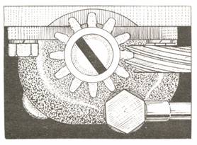
Figure 1. Orientation for DKY

Figure 2. Orientation for D.M.2
NOTE:
As the oil pump is pushed into its home position, the driven gear and spindle
assembly will rotate as it meshes with the drive gear. This rotation has to be
taken into account.
100. Install
the oil delivery pipe. Use a new gasket at the delivery elbow and use locking
wire to secure the banjo bolt. Later, larger diameter oil delivery pipes are
secured with Allen socket head cap screws.
NOTE:
The delivery pipe must be installed before the valve timing sprockets and chain
are installed.
Special Note About Valve Timing
101. The
valve timing with respect to the Jowett engine is extremely critical. Great
care must be taken when setting the valve timing. Two pieces of specialist
equipment are required:
An
accurate 360 degree engine timing disc.
An
accurate dial indicator measuring device with 0.001” graduations on the clock
face. The plunger must have more than 0.25” (6.4 mm) of free travel when
mounted in position.
Both
of these items require suitable mounting bracketry and hardware. The need to be
mounted on the engine in a manner that instils confidence during the valve
timing procedure.
102. If
the valve timing is not absolutely correct, the performance of the engine will
suffer due to incorrect vacuum characteristics of the air/petrol intake system.
To Set The Valve Timing – Earlier Type
103. It
should be noted that the crankshaft sprocket can be installed either way round.
The positioning of the keyway in the sprocket bore, in relation to the sprocket
chain teeth, is such that half a half tooth radial movement can be achieved by
reversing the sprocket on the shaft.
104. Any
timing marks that may be found on the timing sprockets should be totally
ignored.
NOTE:
Some crankshaft sprockets have been found with timing marks on both front and
rear faces. Such can only add great confusion.
105. Mount
an indicator pointer at one of the front timing cover bolt thread holes.
106. Mount
the crankshaft sprocket and a new timing chain on the crankshaft nose.
107. Mount
an accurate 360° engine timing
disc at the front of the crankshaft. Make sure that it is held snugly, but can
be moved to align zero with the pointer when the crankshaft is at TDC (1 &
2) position
NOTE:
Use a pair of suitable fibre washers and plain washers to hold the timing disc.
108. Using
the flywheel, turn the crankshaft back, so that it is positioned 35° before TDC (1 & 2).
109 Again,
using the flywheel, turn the crankshaft forwards until the pointer registers
accurately with the 12° before
TDC mark on the timing disc.
NOTE:
Be sure that the disc has not slipped on the crankshaft nose bolt.
110. Set
the number one cylinder inlet valve so that there is slight loading of the
valve spring. Do not load too heavily, or the retainer cap could clash with the
valve guide as the camshaft is rotated.
111. Mount
an accurate dial indicator clock to rest on the pushrod end of the number 1
cylinder inlet valve rocker.
NOTE:
The plunger end of the dial indicator must be longitudinally aligned with the
pushrod. It is the actual movement of the push rod that will be measured by the
dial indicator.
NOTE:
The dial indicator plunger should have more than 0.250” of free travel after it
is positioned against the rocker arm.
112. With
the cam follower set accurately on the heel of the cam lobe, adjust the dial
indicator to read exactly zero.
113. Carefully
rotate the camshaft, in clockwise direction when viewed from the front, until
the dial indicator has shown 0.014” movement (valve lift) at the rocker arm.
114. Hold
the camshaft in this position, This position has been determined as the ‘point
of valve opening’ by Jowett Cars Limited.
115. The
camshaft sprocket can now be inserted into the timing chain. The two sprockets
should be offered up to their home positions. There are two holes in the
camshaft sprocket for the setscrews to pass through. It is possible to slip the
camshaft sprocket in the chain until the two holes are positioned over the
threaded holes in the camshaft nose.
Without
moving the crankshaft, nor the camshaft, the sprocket should be oriented so
that the dowel hole in the sprocket aligns with the dowel located in the
camshaft without changing position of either shaft. The camshaft sprocket may
not align with the dowel, it can be slipped within the chain to achieve
alignment. There is also the facility to reverse the sprocket on the crankshaft
nose. Care must be taken to ensure that the crankshaft position is held while
removing the timing disc to facilitate the changeover.
116. Once
accurate dowel alignment has been achieved, push both sprockets fully home.
117. Re-check
the 12° before TDC and 0.014”
push rod lift settings to ensure that no errant movement has taken place during
the installation process.
118. Install
the two camshaft securing setscrews, using a new locking plate.
119. Rotate
the crankshaft two full turns and check that the 0.014” push rod lift coincides
with the 12° position on the
timing disc. Use the flywheel rim to rotate the crankshaft.
120. Should
the valve timing be correct, tighten the camshaft sprocket setscrews and fold
the locking tabs against full flats on the setscrews
NOTE:
Do not hammer the tab over against the setscrew heads. The tabs should be
carefully bent against the flat using a pair of suitable vise-grips.
To Set The Valve Timing – Series III Type
121. It
should be noted that the crankshaft sprocket can be installed either way round.
The positioning of the keyway in the sprocket bore, in relation to the sprocket
chain teeth, is such that half a half tooth radial movement can be achieved by
reversing the sprocket on the shaft.
122. Any
timing marks that may be found on the timing sprockets should be totally
ignored.
123. There
are two types of camshaft sprocket mounting, the later ‘vernier’ type is the
most desirable; The two types are best described as:
Early
type – simple one position mounting on a fixed position dowel.
Later
type – a more complex mounting system with a multi-position dowel.
124. The
later type, commonly known as the Series III, is described here. To set the
valve timing, turn the crankshaft one full revolution so that it is positioned
at TDC (1 & 2) again.
125. Mount
an indicator pointer at one of the front timing cover bolt thread holes.
126. Mount
the crankshaft sprocket and a new timing chain on the crankshaft nose.
NOTE:
The camshaft timing dowel should be removed from the shaft or sprocket and kept
handy for later use in the valve timing procedure..
127. Mount
an accurate 360° engine timing
disc at the front of the crankshaft. Make sure that it is held snugly, but can
be moved to align zero with the pointer when the crankshaft is at TDC (1 &
2) position
NOTE:
Use a pair of suitable fibre washers and a pair of plain washers to hold the
timing disc.
128. Using
the flywheel, turn the crankshaft back so that it is positioned 35° before TDC (1 & 2).
129 Again,
using the flywheel, turn the crankshaft forwards until the pointer registers
accurately with the 12° before
TDC mark on the timing disc.
NOTE:
Be sure that the disc has not slipped on the crankshaft nose bolt.
130. Set
the number one cylinder inlet valve so that there is slight loading of the
valve spring. Do not load too heavily, or the retainer cap could clash with the
valve guide as the camshaft is rotated.
131. Mount
an accurate dial indicator clock to rest on the pushrod end of the number 1
cylinder inlet valve rocker.
NOTE:
The plunger end of the dial indicator must be longitudinally aligned with the
pushrod. It is the actual movement of the push rod that will be measured by the
dial indicator.
NOTE:
The dial indicator plunger should have more than 0.250” of free travel after it
is positioned against the rocker arm.
132. With
the cam follower set accurately on the heel of the cam lobe, adjust the dial
indicator to read zero exactly.
133. Carefully
rotate the camshaft, in clockwise direction when viewed from the front, until
the dial indicator has shown 0.014” movement (valve lift) at the rocker arm.
134. Hold
the camshaft in this position, This position has been determined as the ‘point
of valve opening’ by Jowett Cars Limited.
135. The
camshaft sprocket can now be inserted into the timing chain. The two sprockets
should be offered up to their home positions. There are two large holes in the
camshaft sprocket for the setscrews to pass through. It is possible to slip the
camshaft sprocket in the chain until the two large holes are positioned over
the threaded holes in the camshaft nose.
Without
moving the crankshaft, nor the camshaft, the sprocket should be oriented so
that the dowel can be pushed through the sprocket into one of the camshaft
vernier dowel holes without changing position of either shaft. The camshaft
sprocket may require rotating 180° within the chain to achieve alignment. There is also the facility
to reverse the sprocket on the crankshaft nose. Care must be taken to ensure
that the crankshaft position is held while removing the timing disc to facilitate
the changeover.
136. Once
accurate dowel alignment has been achieved, push both sprockets fully home and
install the timing dowel with the peg facing the camshaft.
137. Re-check
the 12° before TDC and 0.014”
push rod lift settings to ensure that no errant movement has taken place during
the installation process.
138. Install
the two camshaft securing setscrews, using a new locking plate. The plate
should cover the timing dowel.
139. Rotate
the crankshaft two full turns and check that the 0.014” push rod lift coincides
with the 12° position on the
timing disc. Use the flywheel rim to rotate the crankshaft.
140. Should
the valve timing be correct, tighten the camshaft sprocket setscrews and fold
the locking tabs against full flats on the setscrews
NOTE:
Do not hammer the tab over against the setscrew heads. The tabs should be
carefully bent against the flat using a pair of suitable vise-grips.
141. Remove
the valve setting equipment and reset the number one inlet valve as described
at Step 88.
Installation Of The Rear Timing Cover
142. For
detailed instructions for installation of the rear timing cover and its gasket,
refer to Technical Notes – Rear Timing Cover Gasket.
NOTE:
Do not install the engine oil filter element at this stage, refer to Step 154.
143. A
new crankshaft seal should be installed in the front timing cover.
144. Early
timing covers have no provision for camshaft end-float adjustment. There is a spring
loaded plunger located in the camshaft that seats against a wear pad pressed
into the timing cover. A sticking plunger can cause a loud camshaft end-float
knocking sound.
The
plunger should be a free fit in the camshaft, and, upon installation should be
coated with a smear of Nulon L90 Xtreme assembly lubricant. This lubricant
should also be applied to the wear pad in the front timing cover before it is installed.
NOTE:
If the wear pad is loose in the front timing cover, install it using Loctite 680
Adhesive. Lightly clamp in place and allow to cure. Wipe away any excess
adhesive.
145. Later
timing covers feature an adjustable peg, that sets camshaft end-float via screw
adjustment against a fixed thrust pad pressed into the nose of the camshaft.
The
adjustable peg should be screwed fully home (forwards) in the front timing
cover prior to installing the cover onto the engine. Apply a generous smear of Nulon
L90 Xtreme assembly lubricant to the adjustable peg before installing the
cover.
146. Once
the front timing cover has been installed, screw in the adjustable peg so that
it contacts the camshaft nose pad. Apply a small bead of Loctite 518
Mastergasket sealant around the thread of the adjustable peg. Fit the lock nut
and unscrew the adjustable peg one-sixth-of-a-turn away from the camshaft and,
carefully holding this position, tighten the lock nut against the front timing
cover.
WARNING:
Never attempt to make adjustment of the adjustable peg while the engine is running!
147. Install
the oil pressure gauge fitting into the rear timing cover. Use Loctite 469 pipe
thread sealant and do not over tighten the taper thread fitting. The aluminium
thread boss could split.
148. A
new gasket must be used at the front timing cover. If a metal to metal joint is
adopted, the distributor drive will be out of alignment.
149. Install
the oil filler tube, using a small bead of Loctite Blue RTV sealant. Make sure
that the breather valve is correctly oriented so that the copper pipe can be
easily connected.
Installation Of The Dynamo Mount Bracket
150.
The rear dynamo mounting bracket should be installed. Clean the setscrew and
crankcase threads with methylated spirits and apply a smear of Loctite 518
Mastergasket to the setscrew thread. This thread breaks through into an oil-wet
area, and needs to be sealed. The arm of the bracket should be held at right angles
to the crankcase joint line while the setscrew is tightened down.
Engine Oil Sump And Engine Mountings
151. Carefully
wash the engine oil sump, inspect and make sure that no baffle spot welds are
broken.
152. Check
that the oil pump pick-up strainer has 5 – 8 mm clearance to bottom of sump. If
necessary, bend the oil suction pipe carefully to achieve the required
dimension.
153. Install
the horizontal baffle plate assembly.
154. Thoroughly
clean the gasket surfaces with methylated spirits and allow to dry.
NOTE:
It is best to stand the engine assembly on the rear clutch housing face while
the oil sump and engine mountings are being fitted.
155. Apply
a smear of Loctite 515 Mastergasket to both metal joint faces. Make sure that
the sealant is applied evenly and it is continuous inboard of the mounting
studs.
156. Fit
the engine oil sump, with new washer at drain plug, and install Nyloc nuts at
the studs.
157. The
four setscrews at the front should be tightened carefully, because there is not
a great amount of purchase thread depth in the front timing cover.
158. Wipe
away excess sealant.
159. The
engine mount bracket assemblies can now be installed.
Fit The Exhaust Manifolds
160. With
the engine still in its vertical position, the exhaust manifolds and front cross-over
pipe can be easily installed.
161. The
exhaust manifolds should be clean, inside and out. If there is an oily carbon
residue inside the manifold, it can be cleaned out by burning with an
oxy-acetylene torch. This will dry out the carbon deposits and make cleaning
easier.
162. The
gasket flanges must be flat and clean. The flanges should not be cracked or
broken.
163. The
studs screwed into the cylinder head should be in sound condition. It is also
advisable to use new brass nuts. The original nuts have probably been over
tightened and have therefore swollen, making it difficult to have a good
spanner fit.
164. Install
the manifolds, the single outlet one is fitted to the RHS. Make sure that the
gaskets are installed correctly on the cylinder heads.
165. Apply
a smear of Loctite JS1 exhaust gasket sealant to the gasket surfaces, and
install the two manifolds. Use new brass nuts and new spring washers. Care needs
to be taken here – new brass nuts could have been machined from metric hexagon
bar, this will require the use of a metric spanner (usually 12 mm).
NOTE:
Do not over tighten the brass nuts. A brass nut is softer than a normal steel
nut and, therefore, deformation of the hexagon can easily result.
166. The
front cross-over exhaust pipe can now be installed. Ideally, the centre joint
should be a sliding fit, to cope with expansion and contraction with engine
temperature change. Use new exhaust flange gaskets and smear exhaust sealant to
the gasket surfaces prior to assembling with 8 mm stainless steel fixing
hardware.
167. The
engine can now be returned to its normal attitude on the bench stand.
Install The Carburettors
168. Identify
the LHS and RHS carburettors. The RHS carburettor has the brass fitting for the
vacuum advance pipe and the link from the choke that opens the throttles a
small amount when the chokes are actuated.
169. Mount
the carburettors on their packing flanges using new gaskets. It is a good idea
to force Loctite Blue RTV sealant into any space that could be present between
the cylinder head and the sparking plug cover plate. The sealant can be
carefully pushed into the gap with a wooden stirring stick, taking care to
watch for sharp edges on the plate that could shave the stick.
170. The
ball sockets at the ends of the throttle link rod should be clean and lightly
oiled. The ball ends on the throttle actuator arms should be round spheres and
have no flats.
171. The
sliding joint in the throttle link rod assembly must be absolutely free to
slide when setting the rod length. The throttle return spring should return the
throttle arms positively against their stops.
172. Set
the choke control rods so that there is no pulling influence when the chokes
are in the open position, the choke control must, however, completely close the
chokes when the cable is pulled.
NOTE:
Having a degree of ‘pull’ at the choke butterfly arms will cause rapid wear at
the choke spindles.
IMPORTANT!
Ensure that a sound, good contact, earth strap is fitted between the engine (at
starter mount stud) and the car’s chassis. Failure to do so could result in the
choke actuating mechanism carrying most of the electric current while cranking
the engine in cold conditions.
173. Install
the cross-over petrol pipe assembly, using new washers at the banjo fittings.
174. Install
the oil filter element and canister.
175. Set
the carburettor adjustments as described in the Maintenance Manual.
The Petrol Pump
176. The
fuel pump should have its pressure regulated to 1.5 – 2 psi. The bottom end of
the tolerance is the most desirable setting.
177. Lubricate
and install the pump actuator rod. Both ends should be in good condition.
178. Make
sure that the pump mounting flange is absolutely flat and free from burrs.
179. Apply
a smear of Loctite 515 Mastergasket to the gasket surfaces and install the
pump. Ensure that the front timing cover gasket protrudes to make contact with
the petrol pump gasket.
NOTE:
Do not over tighten the attaching setscrews, distortion of the flange could
result.
Filling The Engine Oil Sump
180. After
allowing gasket sealants to fully cure, checking that the sump drain plug is
secure and the engine oil dipstick is clean, fill the sump with new Penrite HPR
30 engine oil to the upper level indicated on the dipstick.
181. Attach
a temporary plug to the oil pressure gauge pipe.
182. Make
sure that the oil filter drain setscrew is tightened against a new fibre
washer. It is a good idea to use a socket (Allen) head setscrew to make use of
the drain facility easier. This is particularly so with the later type oil
filter assemblies that feature oil cooler attachment fittings.
NOTE:
This drain setscrew and its length are most important! If the correct length setscrew
is not screwed fully home, there is a very likely possibility that there will
be no oil pressure on engine start up.
The threaded portion
of the drain setscrew passes through a ‘drain to sump’ oil gallery opening.
183. Make
up a new gasket for the oil filler cap. The gasket can be cut from cork gasket
material to a diameter slightly larger than the threaded part of the cap. The
gasket will then snap into place within the oil filler cap.
The Distributor And Ignition Timing
184. Set
the crankshaft to TDC (1 & 2) on the compression stroke at number 1
cylinder. That is when both push rods for that cylinder can be easily rotated
after setting the crankshaft.
183. Make
sure that the circlip securing the drive shaft to the distributor drive dog is
secure.
184. Install
the distributor, rotate the rotor arm until the drive shaft drops into the
offset dog in the oil pump drive spindle. Leave the advance/retard clamp
bracket loose and attach it to the timing cover with the spacer washer under
the bracket. Use a plain washer, spring washer and nut on the securing stud. Do
not tighten.
185. Set
up a test lamp and battery with negative lead to the distributor body, and the positive
lead to the low tension connection at the distributor.
186. Find
a lobe on the distributor cam such that the position of the distributor body
allows convenient access for the distributor cap retaining clips, and so that
the high tension plug leads are pointing to the rear of the engine. Consideration
should also be given to the vacuum pipe connection.
187. The
test lamp should glow when the correctly adjusted contact points are closed.
Rotate the distributor body clockwise, when viewed from above, until the lamp
just extinguishes. Tighten the distributor clamp screw and the mounting bracket
nut.
188.
Identify the terminal post in the distributor cap to which the rotor arm is
pointing to as number 1 cylinder. From here, work around the distributor cap,
anticlockwise, and allocate the plug leads in the engine’s firing order – 1, 4,
2, 3. The centre high tension lead connects to the ignition coil.
189. Ensure
that the high tension leads are of sufficient length to appear elegant as they
pass through the plug lead supports. There should be a degree of useful slack,
but not to the extent that fouling with the throttle linkage occurs.
190. Make
sure that the vacuum advance/retard pipe is in sound condition and attach it to
the RHS carburettor and the diaphragm on the distributor.
NOTE:
The union nut sizes are SAE and are, 7/16” AF at the carburettor fitting and
3/8” AF at the distributor end fitting.
Clutch And Gearbox Installation
191. Thoroughly
clean the friction faces on the flywheel and the clutch pressure plate. These
surfaces must be clean, dry and absolutely oil-free.
192. Identify
the ‘X’ stamping on clutch and flywheel. Install the clutch friction disc and
pressure plate into the housing. Use a spare gearbox input shaft as a dummy
alignment tool..
193. Apply
a smear of Nulon L90 Xtreme assembly lubricant into the crankshaft spigot bush.
194. Apply
a small amount of Castrol PH Zinc Oxide grease to the clutch friction disc splines.
Keep the amount of white grease to a minimum, as excess grease will be thrown
onto the friction linings. Grease is required here to ensure clean and
efficient clutch operation.
NOTE:
Arrange the friction disc so that the raised side of the hub faces rearwards
(towards the clutch pressure plate).
195. Align
the friction disc with the spigot bush and set the pressure plate over the
dowels. Install the six securing setscrews with new spring washers.
196. As
the crankshaft is rotated, progressively tighten the six setscrews.
197. Withdraw
the clutch friction disc aligning tool.
198. Install
the clutch throwout lever pivot ball into its right hand drive position. Apply
Castrol PH Zinc Oxide grease to the ball and install the fork and throwout
bearing assembly. Apply a minimal smear of white grease at the fork pegs.
199. Hold
the fork and throwout bearing assembly while the pivot ball shank is pushed
forwards. Still holding the assembly, insert the clutch throwout bell into the
rear of the clutch housing, making sure that the notch locates around the pivot
ball shank.
200. Thoroughly
clean the joint faces at the gearbox to clutch housing joint. Apply a smear of
Loctite 518 Mastergasket to one surface. Be careful not to block the breather
tract.
201. Ensure
that the gearbox is kept in ‘neutral’ and insert the first motion shaft into
the clutch friction disc spline. It may be necessary to rotate the gearbox
assembly to facilitate spline engagement. Once aligned, push the gearbox fully
home and install hardware, Wipe away excess sealant.
NOTE:
Attempts to engage a gear could dislodge the first motion shaft and require
dismantling of the gearbox to reset the third motion shaft spigot bearing.
202. Install
the flywheel cover plate.
Water Pump, Dynamo And Starter Motor
203. Using
a suitable hoist, lift the assembled engine from the work bench and mount it on
the engine test stand.
204. Refer
to Technical Notes – Water Pump for additional information about overhauling
the pump.
205. Install
the water pump, using the correct thick-wall hose, and attach the accessory
drive belt adjusting bracket assembly.. Carefully install the water pump pulley
over its drive key and tighten the new Nyloc nut onto a large diameter plain
washer.
206. Install
the two fan stay studs into the crankcase. In some cases the holes break
through into an oil-wet area and the studs should then be installed with an
application of Loctite 515 Mastergasket. The stays, LH and RH should be installed
with double spring washers and slotted nuts. Tighten the nuts so that the stay
is held firmly, but is free to move. Secure the slotted nuts with new split
pins.
NOTE:
Rubber washers can be used in place of the springs and the slotted nuts can be
replaced with thin Nyloc nuts.
207. Later
water pumps have threaded studs for the attachment of the stays to the
extension housing. Nyloc nuts should be used and be tightened so that the plain
washer can be turned easily by hand,
NOTE:
The early style pegs can be cut off the extension housing and exhaust manifold studs
threaded into the housing to upgrade the assembly.
208. The
threaded cooling fan should be fitted with the thin locking nut screwed onto
the fan shaft first. The fan hexagon is then screwed onto the shaft against the
thin nut and tightened firmly.
NOTE:
There should be a minimum gap of 1/32” (0.76 mm) between the nut and the
extension housing.
209. Install
the starter motor. Attach the earth strap to the lower mounting stud.
210. Install
the dynamo. Check that the pulley aligns with the crankshaft pulley. Plain
washers at the two lower mount lugs can be used to set the dynamo further
forward if necessary.
211. Install
the accessory drive belt. Do not over tighten, there should be about ½” of
movement in its longest span.
NOTE:
The setscrew that screws into the upper drive belt tensioner bracket lug on the
dynamo is 5/16” UNC SAE thread.
Engine Start Up
212. The
test stand has the facility to install a coolant radiator. The system should be
filled with soft water and left for a while to allow water leaks to emerge. Any
leaks should be rectified at this time.
213. Connect
a well charged 12 volt battery.
214. Connect
an accurate engine oil pressure gauge.
215. Using
the starter motor, crank the engine (with ignition switched off) until oil pressure
is indicated on the gauge. This could take a while because the engine oil
filter canister is being filled.
NOTE:
Check around engine for oil leaks and rectify any that may have presented themselves.
216. Install
a set of new Champion L87YC sparking plugs. Use new rubber sealing washers at
the plug caps.
217. Provide
an adequate supply of fresh petrol. Prime the carburettors.
218. Apply
full choke and start the engine.
219. With
the engine thoroughly warmed, make tuning adjustments to the carburettors and
ignition timing.
220. Switch
off engine and allow to stabilize for twenty minutes.
220. Remove
the rocker covers and withdraw the valve rocker shaft assemblies.
NOTE:
Push rods can be wedged into their tubes with clean rag pieces to prevent the
cam followers from falling out.
221. Re-torque
the cylinder head nuts.
222. Replace
the valve rocker shaft assemblies.
223. Adjust
the valve tip clearances as described in Steps 85 – 90, once the engine has
fully cooled.
NOTE:
From the point where the valve is fully opened, rotate the crankshaft one full
turn to set the cam follower on the absolute heel of the cam lobe. This method
may be tedious, but due to the Jowett engine’s horizontally opposed cylinder
layout, is very worthwhile.
224. Replace
the rocker covers after observing the rate of oil drips from the rocker shaft
assemblies. If the drip rate is excessive, the shafts and/or rocker arm bushes
will need renewing. Check also for oil leakage at the pipe that feeds the shaft
assemblies. The silver solder joints at the banjos have been known to fracture.
225. The
engine is now ready for installation into the motor car.